EP0592349B1 - Transportbandwaage - Google Patents
Transportbandwaage Download PDFInfo
- Publication number
- EP0592349B1 EP0592349B1 EP93610056A EP93610056A EP0592349B1 EP 0592349 B1 EP0592349 B1 EP 0592349B1 EP 93610056 A EP93610056 A EP 93610056A EP 93610056 A EP93610056 A EP 93610056A EP 0592349 B1 EP0592349 B1 EP 0592349B1
- Authority
- EP
- European Patent Office
- Prior art keywords
- belt
- conveyor
- weighing
- reversing rollers
- weigher
- Prior art date
- Legal status (The legal status is an assumption and is not a legal conclusion. Google has not performed a legal analysis and makes no representation as to the accuracy of the status listed.)
- Expired - Lifetime
Links
Images
Classifications
-
- G—PHYSICS
- G01—MEASURING; TESTING
- G01G—WEIGHING
- G01G11/00—Apparatus for weighing a continuous stream of material during flow; Conveyor belt weighers
- G01G11/006—Special taring or checking devices therefor
-
- G—PHYSICS
- G01—MEASURING; TESTING
- G01G—WEIGHING
- G01G11/00—Apparatus for weighing a continuous stream of material during flow; Conveyor belt weighers
Definitions
- the present invention relates to a conveyor-type weigher, i.e. a weigher for continuous weighing of a flow of materials or single objects being advanced on a conveyor belt above a weighing apparatus which, by way of connected registering means, provides continuous weight information about the material on the overhead belt.
- a conveyor-type weigher i.e. a weigher for continuous weighing of a flow of materials or single objects being advanced on a conveyor belt above a weighing apparatus which, by way of connected registering means, provides continuous weight information about the material on the overhead belt.
- the belts typically of a non-elastic plastics web material, may adapt in the associated double-arched way, and thus, this problem will have been solved.
- a prior art conveyor belt weighing mechanism is known from GB-1156109.
- the weighing belt is guided around the reversing rollers projecting from a supporting machine frame and at their outermost ends being carried on a common side beam which is rigidly fixed in the area between the rollers onto said frame by means of transverse support portions extending through the space inside the path of motion of the weighing belt, the aim being that hereby, it shall be possible to pull off the belt instantly to be exchanged or cleaned, by slackening the belt preferably attained by lifting up a load roller resting against the top side of the return run of the belt.
- the belt length may be minimized when the entire effective belt width passes around straight cylindrical rollers, whereby the length and the weight of the machine frame and the said outer side beam may be minimized, in addition to which, the applied lateral control means will not in any way obstruct an easy removal of the belt, after it has been slackened.
- a load roller weighing down the upper side of the return run of the belt may be used, as already indicated.
- the associated control means are normally incorporated in bulky housing portions at the ends of the roller such that these housings alone will obstruct free sideways removability of the belt.
- this load roller shall serve no other purpose but to weigh down on the return belt run as the lateral control is effected by other means.
- the roller may be lodged, e.g. on pivotal arms being downwardly swivable from the machine frame and the said outer side beams, respectively, such that it can be shifted between a lower position freely on the belt, for the stretching of the belt, and an elevated neutral position leaving the belt in such a slackened state that it can be pulled off easily, sideways over the side beam end of the supporting system.
- a new belt or the same belt having been externally cleaned, may be mounted or remounted in the conveyor-type weigher with a minimum of time consumed, because the belt can freely be slipped over the reversing rollers and then be tightened for operation by releasing the temporarily elevated load or tension roller for affecting the return belt run.
- Such an exchange operation will be feasible in just a few minutes, which is unique when compared to the relevant known art.
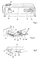
- the shown conveyor-type weigher comprises an apparatus housing with an upright chassis plate 2 on which is placed bearings 4 for projecting shafts for the support of reversing rollers 6 and 8 for a weighing belt 10.
- the rollers 6 and 8, or rather the outermost ends of the support shafts of these, are supported in carrier portions 12 positioned at the ends of a freely supported side beam 14 extending between the two rollers 6 and 8.
- This beam 14 is rigidly fixed to the machine frame plate by way of connecting rods 16 placed below the upper side plane of the rollers 6,8.
- a heavy roller 18 resting against the upper side of the return run of the belt 10, this roller being suspended in pivotal arms 20 which, in a swivable way, are oblique downwardly extending from upper fix points 22 on the beam 14 and the chassis plate 2, respectively.
- a handle 24 which can be turned between an embedded stand-by position and the shown projecting service position in which the handle can be used for the up-swing of the roller 18 into an elevated position in a suitable temporary locking engagement with the beam 14, such that the belt 10 can thusly be slackened.
- the conveyor-type weigher is preferably to be housed in a cabinet which, naturally, is also preferably to be as small as possible. On its front, this cabinet may have a removable panel part 26 which can be removed when the belt 10 is due to be exchanged.
- the said swivable lodging of the handle 24 serves to reduce the width of the apparatus as this need not be bigger than to leave room for the folded handle, which only needs to be unfolded, anyway, when the front panel 26 has been temporarily removed.
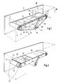
- a couple of horizontal support plates 30 are placed extending from the respective reversing rollers 4,6, and 8 inwardly towards the middle of the belt run where, inbetween these, they border a free belt section which, approximately at the middle, pass above a transverse weighing beam 32, the upper side of which is positioned flush with the plates 30, and which at its mid-section is supported on a fixed pin 34 upwardly protruding from a single-point weighing cell 36, of the type made with an absorber housing mechanically absorbing occurring vibrations between the pin 34 and the interior of the weighing cell 36.
- the weighing cell 36 is connected to a computer, not shown, which continuously registers the weight of the material being advanced on the weighing belt 10, i.e. the material is weighed with equal sufficiency whether it is advanced along the middle or along the sides of the belt 10.
- an opening 38 is made through which materials can be fed to be weighed on the belt 10.
- downwardly protruding guidance plates 40 are placed reaching almost all the way down to the belt 10, positioned such that one material supplied through the opening 36 will be deposited on the belt somewhat within the side edges of same.
- the reversing rollers 4 are made with outer slightly down-turned end portions 41 which, through more or less sharp transitions 42, continue in an absolutely straight and preferably completely smooth circular cylindrical interjacent portion 44 of these rollers.
- the transitions 42 are located at a distance of a few centimetres within the outer side edges of the belt 10, and, as mentioned before, it appears that through this simple arrangement, an efficient belt control in the lateral direction of movement of the belt can be achieved, such that the interjacent portions 44 of the rollers can remain straight cylindrical and thus condition that the belt 10 be uniformly tightened throughout the mid-section on which the flow of materials from the feeder opening 36 will be deposited.
- Fig. 3 the apparatus is shown from above and from the rear side, and the inlet opening 38 on the upper side of the apparatus cabinet is clearly visible. Furthermore, it will be seen that on the rear side of the chassis plate 2, a projecting box part 50 is placed which supports externally an electro motor 52 running one of the rollers 4 through a transmission case 54, while the box part 50 at its opposite end has a detachable cover plate 56 covering an inserted sensor gaging the rotational speed of the passively driven cylinder 4; attached to the apparatus is a control part priming the prime motor 52 to such a velocity that the passive roller 8 is rotated with the exact speed matching the desired feeding speed of the belt 10.
- a transverse scraper-blade 50 At the driven roller 6 is placed a transverse scraper-blade 50, the top edge of which presses inwardly against the outside of the roller-supported belt 10.
- the blade 50 is mounted on the end portion of a U-shaped support part 52 being pivotally lodged on a pin 54 protruding from the chassis plate 2, and which continues in a rod 56 on which is mounted a sliding weight 58.
- the shaft pin 54 may be mounted on an angle- allignable arm 60, in Fig. 5.
- the release of the scraper-blade 50 from the belt 10 is easily achieved by swinging the rod 56 a little upwards, and between the shaft pin 54 and the support part 52, holding means may be inserted for the temporary locking of the system 50, 56 in the thus free-swung position.
- a double-sidedly plough-shaped scraper-plate 61 is placed, being reversibly fixed to a downwardly protruding console part 64 at the middle of a U-shaped plate bracket 66 pivotally fixed to the ends of the shaft of the roller 18.
- This plate 62 scrapes off and removes occurring residues from the inner side of the belt 10, and in case of the plate being worn-down, it can be re-mounted in reverse position.
- a coupling mechanism may be inserted which, by an up-swing of the arms 20, also produces a lifting-up of the scraper-plate 62 from the belt 10 such that, subsequently, the belt will be completely disengaged to be pulled off sideways.
Landscapes
- Physics & Mathematics (AREA)
- General Physics & Mathematics (AREA)
- Structure Of Belt Conveyors (AREA)
- Measuring Pulse, Heart Rate, Blood Pressure Or Blood Flow (AREA)
- Finger-Pressure Massage (AREA)
- Thermotherapy And Cooling Therapy Devices (AREA)
- Transition And Organic Metals Composition Catalysts For Addition Polymerization (AREA)
- Dental Preparations (AREA)
- Inorganic Insulating Materials (AREA)
- Belt Conveyors (AREA)
- Formation And Processing Of Food Products (AREA)
- Fish Paste Products (AREA)
Claims (4)
- Bandwaage mit einem Wägeband, das einen Wiegebereich passiert und mit einem im wesentlichen geraden Lauf zwischen den Oberseiten entsprechender Umkehrwalzen angetrieben ist, dadurch gekennzeichnet, daß die Umkehrwalzen mit einem geraden zylindrischen Zwischenabschnitt, dessen Länge kürzer als die Breite des Bandes ist, und mit gegenüberliegenden Endabschnitten ausgebildet sind, deren Durchmesser schmaler als der des Zwischenabschnittes ist, so daß das Band an den Seiten über einen steilen Übergang vom Zwischen- zum Endabschnitt hinausragt.
- Bandwaage nach Anspruch 1, dadurch gekennzeichnet, daß die Waage Führungsplatten (40) für die Abwärtsführung der zu wiegenden Güter umfaßt, um die Güter einzig und allein auf dem Bandabschnitt, der mit dem Zwischenabschnitt der Umkehrwalzen zusammenwirkt, abzugeben.
- Bandwaage nach Anspruch 1, dadurch gekennzeichnet, daß sie mit Umkehrwalzen ausgebildet ist, die zwischen einem bodengestützten Maschinenchassis und einem Auslegerstützbalken angebracht sind, der an dem Chassis mittels Stützteilen innerhalb des Umfanges des Wägebandes befestigt sind, und daß eine Spannwalze zum Spannen des Bandes durch Pressen gegen den unteren Lauf des Bandes hebbar ist, um eine Arretierposition zu erreichen, in der das Band seitwärts von der Waage entfernbar bzw. darin einsetzbar ist.
- Bandwaage nach Anspruch 1, dadurch gekennzeichnet, daß an der Oberseite des unteren Bandtrums ein pflugförmiges Schabe- oder Kratzelement angeordnet ist, um die innere Oberfläche des Bandes, die den Umkehrwalzen gegenüberliegt, glattzuschaben.
Applications Claiming Priority (2)
| Application Number | Priority Date | Filing Date | Title |
|---|---|---|---|
| DK121792A DK170003B1 (da) | 1992-10-05 | 1992-10-05 | Båndvægt |
| DK1217/92 | 1992-10-05 |
Publications (2)
| Publication Number | Publication Date |
|---|---|
| EP0592349A1 EP0592349A1 (de) | 1994-04-13 |
| EP0592349B1 true EP0592349B1 (de) | 1997-07-23 |
Family
ID=8102301
Family Applications (1)
| Application Number | Title | Priority Date | Filing Date |
|---|---|---|---|
| EP93610056A Expired - Lifetime EP0592349B1 (de) | 1992-10-05 | 1993-10-05 | Transportbandwaage |
Country Status (5)
| Country | Link |
|---|---|
| EP (1) | EP0592349B1 (de) |
| AT (1) | ATE155880T1 (de) |
| DE (1) | DE69312419D1 (de) |
| DK (1) | DK170003B1 (de) |
| NO (1) | NO933561L (de) |
Cited By (1)
| Publication number | Priority date | Publication date | Assignee | Title |
|---|---|---|---|---|
| US7015400B2 (en) | 2001-08-03 | 2006-03-21 | Marel Hf | Apparatus and method for controlling the belt tension of a belt weigher |
Families Citing this family (9)
| Publication number | Priority date | Publication date | Assignee | Title |
|---|---|---|---|---|
| US5547034A (en) * | 1994-01-10 | 1996-08-20 | Accu-Sort Systems, Inc. | Conveyor friction scale |
| AU2543999A (en) * | 1998-01-20 | 1999-08-02 | Marel Hf. | Method and apparatus for weighing |
| DE102007020311A1 (de) * | 2007-04-17 | 2008-10-30 | Bizerba Gmbh & Co. Kg | Wäge-Fördervorrichtung |
| CN103278224B (zh) * | 2013-04-28 | 2016-04-20 | 九江七所精密机电科技有限公司 | 一种电子皮带秤 |
| CN104635606B (zh) * | 2014-12-11 | 2020-08-18 | 南京梅山冶金发展有限公司 | 一种平整称重数据传输控制方法 |
| CN109436689A (zh) * | 2018-10-24 | 2019-03-08 | 唐山钢铁集团有限责任公司 | 称量皮带自动调整装置 |
| CN112050916B (zh) * | 2020-06-22 | 2021-11-30 | 华东理工大学 | 一种基于称重托辊的振动频率测量物料总质量的方法 |
| EP3985363B1 (de) | 2020-10-16 | 2023-12-27 | Bizerba SE & Co. KG | Förderbandwaage mit förderband sowie förderbandkörper |
| CN112729493B (zh) * | 2020-12-18 | 2022-03-04 | 南京创丰自动化仪表有限公司 | 一种高精度给料皮带秤 |
Family Cites Families (2)
| Publication number | Priority date | Publication date | Assignee | Title |
|---|---|---|---|---|
| DE1549285B2 (de) * | 1967-04-12 | 1972-01-20 | Carl Schenck Maschinenfabrik Gmbh, 6100 Darmstadt | Dosierbandwaage |
| US3944050A (en) * | 1974-03-11 | 1976-03-16 | K-Tron Corporation | Gravimetric feeder |
-
1992
- 1992-10-05 DK DK121792A patent/DK170003B1/da not_active IP Right Cessation
-
1993
- 1993-10-05 AT AT93610056T patent/ATE155880T1/de active
- 1993-10-05 DE DE69312419T patent/DE69312419D1/de not_active Expired - Lifetime
- 1993-10-05 EP EP93610056A patent/EP0592349B1/de not_active Expired - Lifetime
- 1993-10-05 NO NO933561A patent/NO933561L/no unknown
Cited By (1)
| Publication number | Priority date | Publication date | Assignee | Title |
|---|---|---|---|---|
| US7015400B2 (en) | 2001-08-03 | 2006-03-21 | Marel Hf | Apparatus and method for controlling the belt tension of a belt weigher |
Also Published As
| Publication number | Publication date |
|---|---|
| NO933561L (no) | 1994-04-06 |
| DK121792D0 (da) | 1992-10-05 |
| NO933561D0 (no) | 1993-10-05 |
| EP0592349A1 (de) | 1994-04-13 |
| DK121792A (da) | 1994-04-06 |
| DE69312419D1 (de) | 1997-08-28 |
| ATE155880T1 (de) | 1997-08-15 |
| DK170003B1 (da) | 1995-04-24 |
Similar Documents
| Publication | Publication Date | Title |
|---|---|---|
| EP0592349B1 (de) | Transportbandwaage | |
| JP3345043B2 (ja) | ばら荷または液体の供給装置 | |
| US5865997A (en) | Scraper blade assembly | |
| US3927844A (en) | Cloth inspection device | |
| US4342412A (en) | Tilt-box for guiding a continuously moving web | |
| US5491877A (en) | Apparatus for vertically displacing a shiftable bottom of a coiler can | |
| GB2041315A (en) | An Endless Belt Conveyor Unit | |
| JPH0680229A (ja) | ベルトコンベア手段 | |
| JP3009518B2 (ja) | 計量ベルト・フィーダ | |
| CN109436732A (zh) | 一种用于高炉水渣皮带二次刮料装置 | |
| KR200262975Y1 (ko) | 벨트컨베이어 텐션부의 사행조정장치 | |
| JPH0616297A (ja) | 横方向で安定したウェブをガイドする装置 | |
| CN109702041B (zh) | 一种吊装滑轨式放料架 | |
| US4386679A (en) | Transfer device especially for product checkout systems in stores | |
| EP0569073A1 (de) | Förderer | |
| US4123321A (en) | Removable head box for a paper making machine | |
| US3941367A (en) | Fabric layering machine | |
| JP3183742B2 (ja) | 搬送コンベアのガイド装置 | |
| JPH08324744A (ja) | ベルトコンベア | |
| US4593725A (en) | Cloth inspection stand for loom takeup | |
| JP2729271B2 (ja) | コンベア装置 | |
| JPH0730218U (ja) | 乾燥施設等における横送りチェンコンベヤ装置 | |
| JP3585732B2 (ja) | ワークガイド付計量装置 | |
| US2781541A (en) | Adjustments of a scraper blade in a roller mill | |
| US5785226A (en) | Power drive loop stand |
Legal Events
| Date | Code | Title | Description |
|---|---|---|---|
| PUAI | Public reference made under article 153(3) epc to a published international application that has entered the european phase |
Free format text: ORIGINAL CODE: 0009012 |
|
| AK | Designated contracting states |
Kind code of ref document: A1 Designated state(s): AT BE CH DE DK ES FR GB GR IT LI NL PT SE |
|
| 17P | Request for examination filed |
Effective date: 19941001 |
|
| GRAG | Despatch of communication of intention to grant |
Free format text: ORIGINAL CODE: EPIDOS AGRA |
|
| 17Q | First examination report despatched |
Effective date: 19960705 |
|
| GRAH | Despatch of communication of intention to grant a patent |
Free format text: ORIGINAL CODE: EPIDOS IGRA |
|
| RAP1 | Party data changed (applicant data changed or rights of an application transferred) |
Owner name: SPROUT-MATADOR A/S |
|
| GRAH | Despatch of communication of intention to grant a patent |
Free format text: ORIGINAL CODE: EPIDOS IGRA |
|
| GRAA | (expected) grant |
Free format text: ORIGINAL CODE: 0009210 |
|
| RAP1 | Party data changed (applicant data changed or rights of an application transferred) |
Owner name: JESMA VEJETEKNIK APS |
|
| AK | Designated contracting states |
Kind code of ref document: B1 Designated state(s): AT BE CH DE DK ES FR GB GR IT LI NL PT SE |
|
| PG25 | Lapsed in a contracting state [announced via postgrant information from national office to epo] |
Ref country code: NL Free format text: LAPSE BECAUSE OF FAILURE TO SUBMIT A TRANSLATION OF THE DESCRIPTION OR TO PAY THE FEE WITHIN THE PRESCRIBED TIME-LIMIT Effective date: 19970723 Ref country code: LI Effective date: 19970723 Ref country code: IT Free format text: LAPSE BECAUSE OF FAILURE TO SUBMIT A TRANSLATION OF THE DESCRIPTION OR TO PAY THE FEE WITHIN THE PRE;WARNING: LAPSES OF ITALIAN PATENTS WITH EFFECTIVE DATE BEFORE 2007 MAY HAVE OCCURRED AT ANY TIME BEFORE 2007. THE CORRECT EFFECTIVE DATE MAY BE DIFFERENT FROM THE ONE RECORDED.SCRIBED TIME-LIMIT Effective date: 19970723 Ref country code: GR Free format text: LAPSE BECAUSE OF FAILURE TO SUBMIT A TRANSLATION OF THE DESCRIPTION OR TO PAY THE FEE WITHIN THE PRESCRIBED TIME-LIMIT Effective date: 19970723 Ref country code: FR Effective date: 19970723 Ref country code: ES Free format text: THE PATENT HAS BEEN ANNULLED BY A DECISION OF A NATIONAL AUTHORITY Effective date: 19970723 Ref country code: DK Effective date: 19970723 Ref country code: CH Effective date: 19970723 Ref country code: BE Effective date: 19970723 Ref country code: AT Effective date: 19970723 |
|
| REF | Corresponds to: |
Ref document number: 155880 Country of ref document: AT Date of ref document: 19970815 Kind code of ref document: T |
|
| REG | Reference to a national code |
Ref country code: CH Ref legal event code: EP |
|
| REF | Corresponds to: |
Ref document number: 69312419 Country of ref document: DE Date of ref document: 19970828 |
|
| PG25 | Lapsed in a contracting state [announced via postgrant information from national office to epo] |
Ref country code: SE Effective date: 19971023 Ref country code: GB Free format text: LAPSE BECAUSE OF NON-PAYMENT OF DUE FEES Effective date: 19971023 |
|
| PG25 | Lapsed in a contracting state [announced via postgrant information from national office to epo] |
Ref country code: DE Effective date: 19971024 |
|
| PG25 | Lapsed in a contracting state [announced via postgrant information from national office to epo] |
Ref country code: PT Effective date: 19971030 |
|
| EN | Fr: translation not filed | ||
| NLV1 | Nl: lapsed or annulled due to failure to fulfill the requirements of art. 29p and 29m of the patents act | ||
| REG | Reference to a national code |
Ref country code: CH Ref legal event code: PL |
|
| PLBE | No opposition filed within time limit |
Free format text: ORIGINAL CODE: 0009261 |
|
| STAA | Information on the status of an ep patent application or granted ep patent |
Free format text: STATUS: NO OPPOSITION FILED WITHIN TIME LIMIT |
|
| GBPC | Gb: european patent ceased through non-payment of renewal fee |
Effective date: 19971023 |
|
| 26N | No opposition filed |