EP0590535B1 - Illumination type electronic part of rotational operation - Google Patents
Illumination type electronic part of rotational operation Download PDFInfo
- Publication number
- EP0590535B1 EP0590535B1 EP93115454A EP93115454A EP0590535B1 EP 0590535 B1 EP0590535 B1 EP 0590535B1 EP 93115454 A EP93115454 A EP 93115454A EP 93115454 A EP93115454 A EP 93115454A EP 0590535 B1 EP0590535 B1 EP 0590535B1
- Authority
- EP
- European Patent Office
- Prior art keywords
- rotational operation
- operation shaft
- rotor
- illumination type
- electronic part
- Prior art date
- Legal status (The legal status is an assumption and is not a legal conclusion. Google has not performed a legal analysis and makes no representation as to the accuracy of the status listed.)
- Expired - Lifetime
Links
Images


Classifications
-
- H—ELECTRICITY
- H01—ELECTRIC ELEMENTS
- H01C—RESISTORS
- H01C10/00—Adjustable resistors
- H01C10/14—Adjustable resistors adjustable by auxiliary driving means
-
- H—ELECTRICITY
- H01—ELECTRIC ELEMENTS
- H01C—RESISTORS
- H01C10/00—Adjustable resistors
- H01C10/30—Adjustable resistors the contact sliding along resistive element
- H01C10/38—Adjustable resistors the contact sliding along resistive element the contact moving along a straight path
Definitions
- the present invention relates to an illumination type electronic part of rotational operation, which is mainly used in audio equipment and capable of indicating clearly the operational positions of its knob by means of light from a built-in light source such as an LED (Light Emitting Diode).
- a built-in light source such as an LED (Light Emitting Diode).
- a motor-driven illumination type variable resistor of rotational operation will be explained as an example of the prior art illumination type electronic part of rotational operation with the help of Fig. 5 through Fig. 8.
- the motor-driven illumination type variable resistor of rotational operation is composed of a variable resistor 1, a speed reduction gear mechanism 2, and a motor 3.
- the variable resistor 1 is composed of a metal bushing 5, a resistance varying means, and an illuminating means.
- the bushing 5 has a housing member 4.
- the resistance varying means is composed of a rotational operation shaft 11, which is supported by the bushing 5 and freely rotatable, a driver 12, a brush holder 13, a brush 14, and a resistor substrate 15.
- the rotational operation shaft 11 is integrally formed of a cylindrical member 7 which has a through-hole 6 therein, a flange 8 disposed on the rear end of said cylindrical member 7, a projection 9 disposed at a position of the periphery of said flange 8, and a bow-shaped linkage 10 disposed on the end of said projection 9.
- the brush holder 13 is linked with the bow-shaped linkage 10 by means of a projection for linkage 12A of the driver 12.
- the resistor substrate 15 is held by a substrate holder 19, and a resistor is formed on the surface of said substrate 15.
- the illuminating means is comprised of an LED 16, which serves as a light source and is located inside the concaved housing 4 and at the rear end of the feed-through hole 6 of the rotational operation shaft 11, and a holder 17 for holding the LED 16.
- the rotational motion of the rotational operation shaft 11 is restricted in its extent by the projection 9 of the rotational operation shaft 11 hitting a projection 18 disposed at the lower portion of the concaved portion of the housing 4 of the bushing 5.
- a housing box 20 of the speed reduction gear mechanism 2 and the motor 3 are put together with the back of the substrate holder 19 of the variable resistor 1 and, at the same time, the bushing 5, the substrate holder 19 and the housing box 20 are put together to make an integral body by means of a U shaped bracket 21, to which the motor 3 is fastened by screws.
- This structure makes it possible to transmit the rotational motion of the motor 3 to the driver 12 of the variable resistor 1 through the speed reduction gear mechanism 2.
- the aforementioned structure has presented an inherent difficulty in coping with changes in specifications for the length of the rotational operation shaft 11, the diameter of a knob mounting portion 11A of the rotational operation shaft 11, and the position of a flat portion 11B of the rotational operation shaft 11 to fix the position of a knob against its rotational direction.
- the rotational operation shaft 11 On account of the flange 8 which has a larger diameter than that of a fitting receptacle of the bushing 5 and is integrally molded with the rear end of the rotational operation shaft 11, the rotational operation shaft 11 has to be inserted from the back of the receptacle of the bushing 5 to put together the bushing 5 and the rotational operation shaft 11. Therefore, when a strong thrusting force is applied to the rotational operation shaft 11 from the front at the time of mounting a knob or the like onto the rotational operation shaft 11, there has been a danger of inflicting damages to some component parts such as the resistor substrate 15 or the like.
- a stopper mechanism to restrict the extent of the rotational motion of the rotational operation shaft 11 is built in such a way that the projection 9 of the metallic rotational operation shaft 11 made by a die-casting method or the like hits the projection 18 of the concaved housing 4 of the metallic bushing 5 made by a die-casting method or the like. Accordingly, a hitting sound is generated on account of striking between metals with a resultant annoying adverse effect imposed on electrical parts, especially on the ones intended for use in audio equipment.
- the present invention is to provide a solution to the afore-mentioned problems associated with the prior art and its object is to provide an illumination type electronic part of rotational operation which can readily cope with changes in specifications for a rotational operation shaft, can withstand a strong thrusting force applied to the rotational operation shaft, makes only a small hitting sound at the rotation stopper of the rotational operation shaft and also has such effects as stabilized lighting of the illuminating means disposed on the end of the rotational operation shaft or the like.
- the illumination type electronic part of rotational operation of the present invention has a structure comprising:
- the structure comprises a rotational operation shaft of a simple hollowed cylindrical shape, an elevated step portion for stopping a thrust force disposed on said rotational operation shaft, and a rotor, which has a stopper for restricting the extent of its rotational motion and is prepared separately from the rotational operation shaft by resin molding.
- the foregoing structure makes it possible to cope readily with changes in specifications for the rotational operation shaft and also to prevent damages from inflicting on the substrate when the rotational operation shaft is manipulated, and furthermore has such effects as prevention of abnormal sound generation or the like.
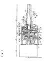
- Fig. 1 is a sectional side view of an illumination type electronic part of rotational operation as one of the exemplary embodiments of the present invention.
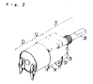
- Fig. 2 is a perspective view of an illumination type electronic part of rotational operation as one of the exemplary embodiments of the present invention.
- Fig. 3 is an exploded illustration of a variable resistor forming a principal portion of an illumination type electronic part of rotational operation as one of the exemplary embodiments of the present invention.
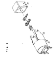
- Fig. 4 is an exploded illustration of a speed reduction gear mechanism forming a principal portion of an illumination type electronic part of rotational operation as one of the embodiments of the present invention.
- Fig. 5 is a sectional side view of a prior art illumination type electronic part of rotational operation.
- Fig. 6 is a perspective view of a prior art illumination type electronic part of rotational operation.
- Fig. 7 is an exploded perspective illustration of a variable resistor forming a principal portion of a prior art illumination type electronic part of rotational operation.
- Fig. 8 is an exploded perspective illustration of a speed reduction gear mechanism forming a principal portion of a prior art illumination type electronic part of rotational operation.
- FIG. 1 through Fig. 4 show the structure of a motor-driven illumination type variable resistor of rotational operation as one of the exemplary embodiments of the present invention.
- the motor-driven illumination type variable resistor of rotational operation is composed of a variable resistor 31, a speed reduction gear mechanism 32, and a motor 33.
- the variable resistor 31 is further made up of a bushing 35, a resistance varying means, and an illuminating means.
- the bushing 35 is composed of a concaved housing 34 disposed on its base, a bushing's end Portion 35B extending out to the front, and a circular hole 35A in its central portion, and also is molded by metal or resin.
- the resistance varying means is composed of a cylindrical rotational operation shaft 38, a rotor 44 made of resin, a driver 40 made by a metal die-casting method, a brush 47, and a resistor substrate 48.
- the rotational operation shaft 38 is comprised of an elevated step portion 36 disposed on its periphery to come into contact with the bushing's end portion 35B, a feed-through hole 37 slightly tapered off from a larger diameter hole 37A at the rear end to a smaller diameter hole 37B at the front end, and a flat portion 38A which can be changed in its position freely, and is fitted into and supported by said circular hole 35A of the bushing 35.
- the rotor 44 is comprised of a stopper 39 disposed on its periphery for restricting the extent of rotational motion of the rotational operation shaft 38, a fitting hole 41 disposed on its rear end to put the driver 40 in motion, a recess 42 disposed in its center, and a transparent convex lens 43 for light collection disposed in the front end of the recess 42 at a position which corresponds to a place a little recessed from the larger diameter portion 37A located in the rear end of the rotational operation shaft 38.
- the rotor 44 is prepared separately from the rotational operation shaft 38 and put together with the rotational operation shaft 38 by staking to its rear end.
- the rotor 44 can also be formed integrally with the lens 43 by employing a transparent molding resin.
- the driver 40 is comprised of an arm 45 which has a projection 45A disposed on its end and engaged with the fitting hole 41 of the rotor 44, and a center shaft 40A extending backward.
- the brush 47 is disposed on a brush holder 46 and inter-linked with the center shaft 40A of the driver 40 for rotating together with the center shaft 40A.
- the resistor substrate 48 is held by a substrate holder 53 and a resistor element is formed on its surface.
- the brush 47 slides on the resistor substrate 48.
- the illuminating means is comprised of a light emitting device (LED) 49 disposed inside the concaved housing 34 of the bushing 35 along the direction of the feed-through hole 37 of the rotational operation shaft 38 from the recess 42 of the rotor 44, an insulating resin-made holder 50 to hold said LED 49 to a position behind the transparent convex lens 43, and terminal leads 51 for connection with an outside power source for the LED 49.
- LED light emitting device
- a restriction is placed on the extent of rotational motion of the rotational operation shaft 38 by the stopper 39 which is disposed on the resin-made rotor 44 and is hitting a projection 52 disposed on the lower portion of the concaved housing 34 of the bushing 35.
- a housing box 54 for containing the speed reduction gear mechanism 32 and the motor 33 are mounted behind the substrate holder 53 of the variable resistor 31.
- the bushing 35, the substrate holder 53, and the housing box 54 are all put together to complete an integral body by means of a U shaped bracket 55 fastened to the motor 33 by screws.
- the rotational motion of the motor 33 is transmitted to the driver 40 of the variable resistor 31 through the speed reduction gear mechanism 32.
- a voltage is applied across the terminals 51 and the LED 49 is activated to emit light.
- the emitted light is focused by the transparent convex lens 43 at the front, and reflected by the tapered inner surfaces of the feed-through hole 37 of the rotational operation shaft 38, and illuminates an indicator of a knob (not shown in drawings) mounted on the end of the rotational operation shaft 38.
- the end portion of the rotational operation shaft 38 is flattened to have a cut surface 38A for mounting the knob. on account of this requirement, the feed-through hole 37 is made smaller in its diameter toward its end to get the smaller diameter hole 37B.
- the speed reduction gear mechanism 32 is formed of a friction clutch 58 comprising a last stage reduction gear 56 and a friction spring 57, and coming into contact with the center shaft 40A of the driver 40.
- the rotational motion of the motor 33 is transmitted to the driver 40 through the friction clutch 58.
- said friction clutch 58 is forced to slip.
- the illumination type electronic part of the present invention as defined in claim 1 is characterized by having a rotational operation shaft 38, which is a simple hollowed cylinder, and disposed with an elevated step portion 36 to serve as a stopper against a thrust force, and by preparing a rotor 44 disposed with a stopper 39 for restricting the extent of rotational motion separately from the rotational operation shaft 38, and in addition by use of a molding resin for preparing the rotor 44.
- the simple hollowed cylindrical shape adopted in the rotational operation shaft has made it possible to cope with changes in specifications for the rotational operation shaft in length, diameter or the like within a short period for low cost since it can be produced easily by machining such as cutting and scraping without the necessity of using dies for die-cast molding or the like.
- the light emitted from the light emitting device in the rear end of the feed-through hole of the rotational operation shaft is intensified by said light collecting lens and the indicator on the end of the rotational operation shaft is illuminated brightly.
- the light is propagated by reflection along the tapered surface walls inside the feed-through hole to light up efficiently the indicator on the end of the rotational operation shaft even if said feed-through hole is small in diameter toward the end of the rotational operation shaft.
- the rotor made of a transparent resin and put together integrally with the light collecting lens, it has become possible not only to facilitate the assembly of the lens but also to illuminate the end portion of the rotational operation shaft more efficiently.
Landscapes
- Engineering & Computer Science (AREA)
- Microelectronics & Electronic Packaging (AREA)
- Adjustable Resistors (AREA)
- Rotary Switch, Piano Key Switch, And Lever Switch (AREA)
Applications Claiming Priority (2)
| Application Number | Priority Date | Filing Date | Title |
|---|---|---|---|
| JP261186/92 | 1992-09-30 | ||
| JP4261186A JP2894107B2 (ja) | 1992-09-30 | 1992-09-30 | 照光式回転操作形電子部品 |
Publications (3)
| Publication Number | Publication Date |
|---|---|
| EP0590535A2 EP0590535A2 (en) | 1994-04-06 |
| EP0590535A3 EP0590535A3 (enExample) | 1994-08-03 |
| EP0590535B1 true EP0590535B1 (en) | 1996-05-22 |
Family
ID=17358334
Family Applications (1)
| Application Number | Title | Priority Date | Filing Date |
|---|---|---|---|
| EP93115454A Expired - Lifetime EP0590535B1 (en) | 1992-09-30 | 1993-09-24 | Illumination type electronic part of rotational operation |
Country Status (5)
| Country | Link |
|---|---|
| US (1) | US5575235A (enExample) |
| EP (1) | EP0590535B1 (enExample) |
| JP (1) | JP2894107B2 (enExample) |
| KR (1) | KR970004564B1 (enExample) |
| DE (1) | DE69302784T2 (enExample) |
Families Citing this family (4)
| Publication number | Priority date | Publication date | Assignee | Title |
|---|---|---|---|---|
| JP4302482B2 (ja) * | 2003-10-22 | 2009-07-29 | アルプス電気株式会社 | 回転型電気部品 |
| JP4731936B2 (ja) | 2005-02-09 | 2011-07-27 | 本田技研工業株式会社 | 回転式可変抵抗器 |
| US7877387B2 (en) * | 2005-09-30 | 2011-01-25 | Strands, Inc. | Systems and methods for promotional media item selection and promotional program unit generation |
| KR101134603B1 (ko) * | 2008-10-06 | 2012-04-09 | 엘지이노텍 주식회사 | 스테핑 모터 |
Family Cites Families (15)
| Publication number | Priority date | Publication date | Assignee | Title |
|---|---|---|---|---|
| JPS5241354Y2 (enExample) * | 1971-10-06 | 1977-09-19 | ||
| DE2263183C3 (de) * | 1971-12-29 | 1975-09-18 | Matsushita Electric Industrial Co., Ltd., Kadoma, Osaka (Japan) | Einstellbarer Drehwiderstand mit optischer Anzeige |
| US3920986A (en) * | 1974-02-28 | 1975-11-18 | Finnigan Corp | Mass spectrometer system having synchronously programmable sensitivity |
| US3997864A (en) * | 1974-05-31 | 1976-12-14 | Matsushita Electric Industrial Co., Ltd. | Variable resistor |
| US3920980A (en) * | 1974-07-18 | 1975-11-18 | Nath Guenther | Flexible light guide |
| GB2112166B (en) * | 1981-11-14 | 1986-03-12 | Kei Mori | Tubular light transmitting element |
| JPS58193603U (ja) * | 1982-06-18 | 1983-12-23 | アルプス電気株式会社 | 照光式可変抵抗器 |
| JPH0532965Y2 (enExample) * | 1985-11-14 | 1993-08-23 | ||
| JPH0630289B2 (ja) * | 1987-12-10 | 1994-04-20 | 株式会社村田製作所 | 可変抵抗器 |
| US4942064A (en) * | 1988-06-21 | 1990-07-17 | Hickson Corporation | Method for fixing chromated copper arsenate treating agents in wood |
| DE3825320A1 (de) * | 1988-07-26 | 1990-02-01 | Bayer Ag | Verfahren zur herstellung von presswerkstoffen |
| JPH0675841B2 (ja) * | 1988-09-22 | 1994-09-28 | 功 庄田 | 板材の加工機 |
| JPH03222446A (ja) * | 1990-01-29 | 1991-10-01 | Sumitomo Electric Ind Ltd | 半導体ウェーハ |
| JPH03222445A (ja) * | 1990-01-29 | 1991-10-01 | Matsushita Electron Corp | ボンディング装置 |
| JP2926926B2 (ja) * | 1990-07-25 | 1999-07-28 | 松下電器産業株式会社 | モーター駆動可変抵抗器 |
-
1992
- 1992-09-30 JP JP4261186A patent/JP2894107B2/ja not_active Expired - Fee Related
-
1993
- 1993-09-23 US US08/125,657 patent/US5575235A/en not_active Expired - Fee Related
- 1993-09-24 EP EP93115454A patent/EP0590535B1/en not_active Expired - Lifetime
- 1993-09-24 DE DE69302784T patent/DE69302784T2/de not_active Expired - Fee Related
- 1993-09-24 KR KR1019930019583A patent/KR970004564B1/ko not_active Expired - Fee Related
Also Published As
| Publication number | Publication date |
|---|---|
| DE69302784T2 (de) | 1996-09-19 |
| EP0590535A2 (en) | 1994-04-06 |
| JP2894107B2 (ja) | 1999-05-24 |
| JPH06112014A (ja) | 1994-04-22 |
| EP0590535A3 (enExample) | 1994-08-03 |
| DE69302784D1 (de) | 1996-06-27 |
| KR940007907A (ko) | 1994-04-28 |
| KR970004564B1 (ko) | 1997-03-29 |
| US5575235A (en) | 1996-11-19 |
Similar Documents
| Publication | Publication Date | Title |
|---|---|---|
| US6260431B1 (en) | Construction of an on-vehicle lever switch | |
| US5954458A (en) | Cordless drill with adjustable light | |
| US20070210194A1 (en) | Food processing appliance with indicator | |
| CA2211988A1 (en) | Depth-of-cut mechanism for circular saw | |
| US5107243A (en) | Lever switch | |
| JPH11121210A (ja) | プッシュスイッチ付回転型電気部品 | |
| CA2594441A1 (en) | Power tool equipped with light | |
| EP0590535B1 (en) | Illumination type electronic part of rotational operation | |
| JPH11121209A (ja) | プッシュスイッチ付回転型電気部品 | |
| US5826969A (en) | Illuminating screw driver | |
| JP3765550B2 (ja) | 車載用ノブスイッチ装置 | |
| CN1419259A (zh) | 开关触点结构 | |
| US5690049A (en) | Compact gauge assembly | |
| JP2001229779A (ja) | 照光付回転型電気部品の実装構造 | |
| JP3859411B2 (ja) | ワイパ装置 | |
| JP4029725B2 (ja) | 操作装置 | |
| YU71104A (sh) | Univerzalna seckalica sa pogonskom jedinicom | |
| KR950010598Y1 (ko) | 조광식 회전조작형 전기부품 | |
| GB2283556B (en) | Gear assembly | |
| EP1486117A3 (en) | Reel unit and cover member for a spinning reel | |
| US20040208015A1 (en) | Vehicle mirror with internal illumination source and transmitting housing | |
| EP1445849A2 (en) | Motor | |
| KR200264124Y1 (ko) | 가변저항기의 발광 손잡이 | |
| EP0880205A3 (en) | Rotary connector mounting structure | |
| KR102581884B1 (ko) | 차량용 전조등 각도조절장치 |
Legal Events
| Date | Code | Title | Description |
|---|---|---|---|
| PUAI | Public reference made under article 153(3) epc to a published international application that has entered the european phase |
Free format text: ORIGINAL CODE: 0009012 |
|
| AK | Designated contracting states |
Kind code of ref document: A2 Designated state(s): DE FR GB |
|
| PUAL | Search report despatched |
Free format text: ORIGINAL CODE: 0009013 |
|
| AK | Designated contracting states |
Kind code of ref document: A3 Designated state(s): DE FR GB |
|
| 17P | Request for examination filed |
Effective date: 19941013 |
|
| 17Q | First examination report despatched |
Effective date: 19950703 |
|
| GRAH | Despatch of communication of intention to grant a patent |
Free format text: ORIGINAL CODE: EPIDOS IGRA |
|
| GRAA | (expected) grant |
Free format text: ORIGINAL CODE: 0009210 |
|
| AK | Designated contracting states |
Kind code of ref document: B1 Designated state(s): DE FR GB |
|
| REF | Corresponds to: |
Ref document number: 69302784 Country of ref document: DE Date of ref document: 19960627 |
|
| ET | Fr: translation filed | ||
| PLBE | No opposition filed within time limit |
Free format text: ORIGINAL CODE: 0009261 |
|
| STAA | Information on the status of an ep patent application or granted ep patent |
Free format text: STATUS: NO OPPOSITION FILED WITHIN TIME LIMIT |
|
| 26N | No opposition filed | ||
| REG | Reference to a national code |
Ref country code: GB Ref legal event code: IF02 |
|
| PGFP | Annual fee paid to national office [announced via postgrant information from national office to epo] |
Ref country code: FR Payment date: 20060908 Year of fee payment: 14 |
|
| PGFP | Annual fee paid to national office [announced via postgrant information from national office to epo] |
Ref country code: GB Payment date: 20060920 Year of fee payment: 14 |
|
| PGFP | Annual fee paid to national office [announced via postgrant information from national office to epo] |
Ref country code: DE Payment date: 20070920 Year of fee payment: 15 |
|
| GBPC | Gb: european patent ceased through non-payment of renewal fee |
Effective date: 20070924 |
|
| REG | Reference to a national code |
Ref country code: FR Ref legal event code: ST Effective date: 20080531 |
|
| PG25 | Lapsed in a contracting state [announced via postgrant information from national office to epo] |
Ref country code: FR Free format text: LAPSE BECAUSE OF NON-PAYMENT OF DUE FEES Effective date: 20071001 |
|
| PG25 | Lapsed in a contracting state [announced via postgrant information from national office to epo] |
Ref country code: GB Free format text: LAPSE BECAUSE OF NON-PAYMENT OF DUE FEES Effective date: 20070924 |
|
| PG25 | Lapsed in a contracting state [announced via postgrant information from national office to epo] |
Ref country code: DE Free format text: LAPSE BECAUSE OF NON-PAYMENT OF DUE FEES Effective date: 20090401 |