EP0589758B1 - Besonders für Flugzeuge geeigneter wegklappbarer holographischer Strahlkombinierer - Google Patents
Besonders für Flugzeuge geeigneter wegklappbarer holographischer Strahlkombinierer Download PDFInfo
- Publication number
- EP0589758B1 EP0589758B1 EP93402263A EP93402263A EP0589758B1 EP 0589758 B1 EP0589758 B1 EP 0589758B1 EP 93402263 A EP93402263 A EP 93402263A EP 93402263 A EP93402263 A EP 93402263A EP 0589758 B1 EP0589758 B1 EP 0589758B1
- Authority
- EP
- European Patent Office
- Prior art keywords
- arm
- holographic
- combiner
- mirror
- holographic mirror
- Prior art date
- Legal status (The legal status is an assumption and is not a legal conclusion. Google has not performed a legal analysis and makes no representation as to the accuracy of the status listed.)
- Expired - Lifetime
Links
- 238000011144 upstream manufacturing Methods 0.000 claims description 4
- 230000000007 visual effect Effects 0.000 claims description 4
- 238000006073 displacement reaction Methods 0.000 claims 2
- 230000000717 retained effect Effects 0.000 claims 1
- 230000035939 shock Effects 0.000 claims 1
- 239000013078 crystal Substances 0.000 description 14
- 239000011521 glass Substances 0.000 description 11
- 238000012423 maintenance Methods 0.000 description 2
- 230000000873 masking effect Effects 0.000 description 2
- 239000000470 constituent Substances 0.000 description 1
- 230000001627 detrimental effect Effects 0.000 description 1
- 230000000694 effects Effects 0.000 description 1
- 238000001093 holography Methods 0.000 description 1
- 238000009434 installation Methods 0.000 description 1
Images


Classifications
-
- G—PHYSICS
- G02—OPTICS
- G02B—OPTICAL ELEMENTS, SYSTEMS OR APPARATUS
- G02B27/00—Optical systems or apparatus not provided for by any of the groups G02B1/00 - G02B26/00, G02B30/00
- G02B27/01—Head-up displays
- G02B27/0101—Head-up displays characterised by optical features
- G02B27/0103—Head-up displays characterised by optical features comprising holographic elements
-
- G—PHYSICS
- G02—OPTICS
- G02B—OPTICAL ELEMENTS, SYSTEMS OR APPARATUS
- G02B27/00—Optical systems or apparatus not provided for by any of the groups G02B1/00 - G02B26/00, G02B30/00
- G02B27/01—Head-up displays
- G02B27/0149—Head-up displays characterised by mechanical features
-
- G—PHYSICS
- G02—OPTICS
- G02B—OPTICAL ELEMENTS, SYSTEMS OR APPARATUS
- G02B27/00—Optical systems or apparatus not provided for by any of the groups G02B1/00 - G02B26/00, G02B30/00
- G02B27/01—Head-up displays
- G02B27/0101—Head-up displays characterised by optical features
- G02B2027/0123—Head-up displays characterised by optical features comprising devices increasing the field of view
-
- G—PHYSICS
- G02—OPTICS
- G02B—OPTICAL ELEMENTS, SYSTEMS OR APPARATUS
- G02B27/00—Optical systems or apparatus not provided for by any of the groups G02B1/00 - G02B26/00, G02B30/00
- G02B27/01—Head-up displays
- G02B27/0149—Head-up displays characterised by mechanical features
- G02B2027/0154—Head-up displays characterised by mechanical features with movable elements
- G02B2027/0156—Head-up displays characterised by mechanical features with movable elements with optionally usable elements
-
- G—PHYSICS
- G02—OPTICS
- G02B—OPTICAL ELEMENTS, SYSTEMS OR APPARATUS
- G02B27/00—Optical systems or apparatus not provided for by any of the groups G02B1/00 - G02B26/00, G02B30/00
- G02B27/01—Head-up displays
- G02B27/0179—Display position adjusting means not related to the information to be displayed
- G02B2027/0187—Display position adjusting means not related to the information to be displayed slaved to motion of at least a part of the body of the user, e.g. head, eye
Definitions
- the present invention relates to a holographic combiner intended to be mounted on aircraft.
- the images come from a projector placed upstream from the combiner and whose relative position relative to a holographic lens, when it is operational, is fixed.
- Such combiners are maintained and positioned by means of a mechanical device and generally mounted on the ceiling in the cockpit of the aircraft and this is retractable. Examples of such combiners are disclosed in US-A-4,775,218 and US-A-4,188,090.
- the combiner must be able to line up the rest of the time in an area which minimizes the pilot's external field of vision.
- the mechanical holding and positioning devices do not allow the complete retraction of the combiners, part of the mechanism remaining visible in the pilot's field of vision, even when stored.
- these known devices are constituted by two arms arranged on either side of the holographic crystal and are connected to a fixed part top of the cabin ceiling.
- the holographic glass is integral with the arms which support it, which has the drawback of constituting a large assembly, penalizing during storage of the assembly hence the difficulty complete retraction.
- the length generated by this succession of elements can oblige the pilot to have a backward movement to allow their passage when storing or putting the combiner in operational position. Such a movement can be harmful to piloting the aircraft.
- side handles are provided on either side of the holographic glass in order to constitute sockets necessary for maneuvers without touching the holographic glass.
- the invention relates to a retractable holographic combiner, in particular for aircraft of the type comprising a movable holographic lens placed in front of the pilot's eyes and intended for the presentation of luminous images collimated ad infinitum superimposed on the exterior landscape and from a headlamp disposed upstream of said combiner, which holographic lens is connected to a fixed part of the aircraft by means of an articulated support ensuring its maintenance and its positioning, characterized in that the holographic lens support is constituted by a single lateral link arm comprising a first upper articulation connecting it by one of its ends to the part of the aircraft and a second lower articulation connecting said arm by its other end to a side of the holographic glass so to obtain a complete retraction of the assembly by rotation of the holographic crystal on itself around of the lower articulation of the arm, performed before or simultaneously with the rotation of said arm around its upper articulation, until it merges with the lateral side of the holographic crystal on the one hand and it
- Figures 1 and 2 schematically represent a cockpit 1 designated globally and in which a ceiling 2 and a cockpit 3 respectively define an upper visibility limit 4 and lower 5 defining a field of vision 6 of the eye 7 of the pilot .
- the cockpit 1 is equipped with a retractable holographic combiner 8 mounted on the ceiling 2 by means of a fixed part 9.
- the combiner 8 comprises a movable holographic crystal 10, placed in front of the pilot's eyes 7 and intended for the presentation of bright images collimated ad infinitum superimposed on the external landscape and coming from a projector 11, arranged upstream of said combiner 8.
- the holographic glass 10 is connected to the fixed part 9 via an articulated support 12 ensuring its maintenance and positioning.
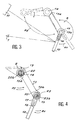
- the support 12 of the holographic crystal 10 is constituted by a single connecting arm 13 comprising a first upper articulation 14 connecting it, by one of its ends 13a, to the fixed part 9 of the aircraft and a second lower articulation 15 connecting said arm 13, by its other end 13b, to an upper part of a lateral side 10a of the holographic crystal 10.
- such a device according to the invention makes it possible to obtain complete retraction of the assembly of the combiner 8 by rotation along R1 of the holographic crystal 10 on itself around the lower articulation 15 of the arm 13 on the one hand, and this until the latter merges with the lateral side 10a of the holographic crystal 10, and on the other hand by rotation along R2 of said arm 13 around its upper articulation 14 until that it is completely raised outside the pilot's external field of vision.
- the folding back of the arm 13 and the holographic glass 10 for a stored position, and conversely their deployment for an operational position, can be carried out by prior rotation along R1 of the holographic glass 10 relative to the arm 13 then by rotation according to R2 of the latter with respect to the fixed part 9 around their respective articulation 15, 14, or can also be carried out by simultaneous movement along R1 and R2 of the holographic crystal 10 and of the arm 13.
- the combiner 8 is maneuvered by means of a grip handle 16 also unique from a single grip in a natural movement of the pilot's arm.
- the grip handle 16 acting in maneuver on the holographic lens assembly 10 - connecting arm 13 is directly connected to the articulation 15 of the holographic lens which crosses the lower end 13a of said arm 13, so that the single arm 13 and the single handle 16 cause only '' minimum visual masking when the unit is deployed.
- the handle 16 is connected to the holographic crystal 10 by means of a retaining bracket 17 arranged in its upper right corner, for example, and secured to the lower articulation 15 for a screw-nut system 18.
- the deflections of the link arm 13 relative to the fixed part 9 of the aircraft and of the holographic glass 10 relative to said arm 13 around their respective upper 14 and lower 15 joints are limited. angularly, so as to ensure good repetition of positioning of the holographic crystal 10 relative to the image projector 11.
- the limitation of the angular deflections of the link arm 13 relative to the fixed part 9 of the aircraft and of the holographic crystal 10 relative to said arm 13 is obtained by means of stops 19 , 20 respectively disposed between the fixed part 9 of the aircraft and the upper end 13a of the arm 13 and between the lower part 13b of the arm 13 and the lateral side of the holographic crystal 10.
- the angular movement of the link arm 13 during deployment of the assembly to an operational position is effected by a rotational movement R2 of the arm going from top to bottom until that its stop 19 comes into contact with the fixed part 9 while the abutment of the holographic glass 10 relative to arm 13 is carried out by a rotary movement R1 opposite to the previous one directed towards the pilot, so that the holographic glass 10 is retracted in the opposite direction, therefore forwards, in the event of choc.
- the upper stop 19a is constituted by a removable cleat engaged in a housing 21 chosen as a function of the angular position of the arm 13 to be obtained, relative to the fixed part 9.
- the housings 21 are produced on an external part of the end 13a of the arm 13 near its articulation 14.
- return springs 22, 23 are interposed between, on the one hand, the fixed part 9 and the link arm 13 and, on the other hand, between said arm 13 and the holographic crystal 10 so as to ensure their respective abutment in an operational position, a locking member (not shown) also ensuring the cancellation of the effect of the springs 22,23, in a position row.
- the spring 22 is compressible in rotation during storage to relax in the operating position of the combiner.
- spring 23 is compressible in rotation during storage to relax in the operating position of the combiner.
- the spring 22 is housed in a sheath 24 of a perpendicular extension 23 of the arm 13 in which the articulation 14 is housed, in fact a cylindrical axis.
- the ends 22a and 22b of the spring 22 are respectively anchored in housings 26, 27 arranged respectively on the fixed part 9 and on the opposite end of the articulation axis 14.
- the spring 23 is housed in a sheath 28 produced in a hub 29 of the arm 13 in which is housed the articulation 15 which is also a cylindrical axis.
- ends 23a and 23b are respectively anchored in housings 30 and 31 formed respectively on a part of the hub 29 of the arm 13 and on the opposite end of the articulation axis 15.
Landscapes
- Physics & Mathematics (AREA)
- General Physics & Mathematics (AREA)
- Optics & Photonics (AREA)
- Diffracting Gratings Or Hologram Optical Elements (AREA)
Claims (6)
- Holographischer, wegklappbarer Kombinierer (8) für insbesondere Flugzeuge, mit einem beweglichen holographischen Spiegel (10), der vor den Augen des Piloten angeordnet ist und zur Präsentation von Leuchtbildern dient, die im Unendlichen mit der umgebenden Landschaft zusammenfallen und von einem Projektor (11) abgegeben werden, der oberhalb des Kombinierers angeordnet ist, wobei der holographische Spiegel (10) durch einen beweglichen Träger (12), der dessen Halt und Einstellung gewährleistet, mit einem festen Teil (9) des Flugzeugs verbunden ist, dadurch gekennzeichnet, daß der Träger (12) des holographischen Spiegels (10) aus lediglich einem seitlich des Spiegels angeordneten Verbindungsarm (13) besteht, der ein erstes, oberes Gelenk (14) umfaßt, welches diesen an einem seiner Enden (13a) mit dem festen Teil (9) des Flugzeugs verbindet, sowie ein zweites, unteres Gelenk (15), welches den Arm (13) an seinem anderen Ende (13b) mit einer Seite (10a) des holographischen Spiegels (10) verbindet, um eine vollständige Wegklappbarkeit der Anordnung durch Drehen (R1) des holographischen Spiegels (10) auf sich selbst um das untere Gelenk (15) des Arms (13) zu erhalten, welches Drehen vor oder gleichzeitig mit der Drehung des Arms um dessen oberes Gelenk erfolgt, bis er einerseits mit der seitlichen Seite des holographischen Spiegels verschmilzt und andererseits vollständig aus dem Sichtfeld des Piloten nach außen entfernt ist, wobei ein dergestaltes Zusammenklappen des Armes und des Spiegels in eine Bereitschaftsstellung und umgekehrt in ihre Betriebsstellung mittels eines Handgriffs erfolgen, der ebenfalls nur mit lediglich einer Hand bedienbar ist.
- Kombinierer nach Anspruch 1, dadurch gekennzeichnet, das der Handgriff (16), der bei seiner Betätigung auf die Anordnung holographischer Spiegel (10)-Verbindungsarm (13) wirkt, dergestalt direkt mit dem Gelenk (15) des holographischen Spiegels verbunden ist, welches durch das untere Ende (13a) des Armes (13) verläuft, daß der lediglich eine Arm (13) und der lediglich eine Griff (16) nur eine minimale Sichtverdeckung hervorrufen, wenn die Anordnung eingeklappt ist.
- Kombinierer nach Anspruch 1, dadurch gekennzeichnet, daß die Verschiebewege des Verbindungsarms (13) in Bezug auf den festen Teil (9) des Flugzeugs und des holographischen Spiegels (10) in Bezug auf den Arm (10) um ihr oberes (14) bzw. unteres (15) Gelenk dergestalt winkelbegrenzt sind, daß eine gute Wiederholbarkeit der Positionierung des holographischen Spiegels (10) bezüglich des Bildprojektors (11) gewährleistet wird.
- Kombinierer nach Anspruch 3, dadurch gekennzeichnet, daß die Winkelbegrenzung der Hin- und Herbewegung des Verbindungsarmes (13) in Bezug auf den festen Teil (9) des Flugzeugs und des holographischen Spiegels (10) in Bezug auf diesen Arm (13) durch Anschläge (19, 20) erzielt wird, die jeweils zwischen dem festen Teil (9) des Flugzeugs und dem oberen Ende (13a) des Arms (13) sowie zwischen dem unteren Ende des Arms (13) und der seitlichen Seite des Spiegels (10) angeordnet sind.
- Kombinierer nach Anspruch 3 oder 4, dadurch gekennzeichnet, daß die winkelverschiebung des Verbindungsarms (13) beim Ausklappen der Anordnung in eine Betriebsstellung durch eine Drehbewegung (R2) des Arms erfolgt, die von oben nach unten verläuft, bis dessen Anschlag (19) gegen den festen Teil (9) anliegt, während das Verfahren des holographischen Spiegels (10) gegen den Anschlag in Bezug auf den Arm (13) durch eine gegenüber der vorangehenden umgekehrte, zu dem Piloten hin gerichtete Drehbewegung (R1) erfolgt, so daß der holographische Spiegel (10) im Falle eines Stoßes in umgekehrter Richtung, d.h. nach vorne, wegklappt.
- Kombinierer nach Anspruch 4 oder 5, dadurch gekennzeichnet, daß Rückholfedern (22, 23) dergestalt zwischen einerseits dem festen Teil (9) und dem Verbindungsarm (13) und andererseits zwischen dem Arm (13) und dem Spiegel (10) angeordnet sind, daß in einer Betriebsstellung ihr Anliegen gegen den jeweiligen Anschlag gewährleistet ist, wobei ein Verriegelungsorgan darüber hinaus die Wirkung der Federn (22, 23) in einer Bereitschaftsstellung aufhebt.
Applications Claiming Priority (2)
| Application Number | Priority Date | Filing Date | Title |
|---|---|---|---|
| FR9211193A FR2696013B1 (fr) | 1992-09-21 | 1992-09-21 | Combineur holographique escamotable, notamment pour aéronef. |
| FR9211193 | 1992-09-21 |
Publications (2)
| Publication Number | Publication Date |
|---|---|
| EP0589758A1 EP0589758A1 (de) | 1994-03-30 |
| EP0589758B1 true EP0589758B1 (de) | 1996-10-30 |
Family
ID=9433685
Family Applications (1)
| Application Number | Title | Priority Date | Filing Date |
|---|---|---|---|
| EP93402263A Expired - Lifetime EP0589758B1 (de) | 1992-09-21 | 1993-09-16 | Besonders für Flugzeuge geeigneter wegklappbarer holographischer Strahlkombinierer |
Country Status (5)
| Country | Link |
|---|---|
| US (1) | US5517337A (de) |
| EP (1) | EP0589758B1 (de) |
| JP (1) | JP3322957B2 (de) |
| DE (1) | DE69305713T2 (de) |
| FR (1) | FR2696013B1 (de) |
Families Citing this family (24)
| Publication number | Priority date | Publication date | Assignee | Title |
|---|---|---|---|---|
| FR2766931B1 (fr) | 1997-08-01 | 1999-10-15 | Sextant Avionique | Dispositif optique pour viseur de casque comportant un miroir aspherique |
| FR2772343B1 (fr) * | 1997-12-12 | 2000-03-03 | Sextant Avionique | Fixation d'un support d'equipement embarque |
| JP3349082B2 (ja) * | 1997-12-16 | 2002-11-20 | 株式会社村上開明堂 | インナーミラーの回避構造 |
| FR2777361B1 (fr) | 1998-04-14 | 2003-06-20 | Sextant Avionique | Amelioration de l'angle de vue d'un ecran lcd par decroisement |
| FR2781892B1 (fr) | 1998-07-28 | 2002-08-30 | Sextant Avionique | Amelioration de l'angle de vue d'un ecran lcd par nouvel empilement de films birefringents |
| FR2784201B1 (fr) | 1998-10-06 | 2003-01-31 | Sextant Avionique | Dispositif optique pour viseur de casque comportant un miroir diffractif |
| GB9908415D0 (en) * | 1999-04-14 | 1999-06-09 | Barr & Stroud Ltd | Head up display |
| GB2353017B (en) * | 1999-08-07 | 2003-07-16 | Marconi Electronic Syst Ltd | Mounting of an optical combiner assembly |
| FR2798969B1 (fr) | 1999-09-24 | 2001-12-07 | Thomson Csf Sextant | Dispositif de verrouillage d'une position d'une piece mobile par rapport a une piece fixe |
| FR2816414B1 (fr) * | 2000-11-03 | 2003-03-07 | Thomson Csf | Combineur glace double pour viseur tete haute |
| FR2816717B1 (fr) | 2000-11-14 | 2003-09-05 | Thomson Csf | Viseur tete haute pour aeronef a pare-brise courbe |
| FR2818393B1 (fr) | 2000-12-19 | 2003-10-10 | Thomson Csf | Procede de fabrication d'un ensemble de viseurs tete haute adaptes a des equipements de type donne |
| JP4387608B2 (ja) * | 2001-03-30 | 2009-12-16 | 矢崎総業株式会社 | 車両表示システム用コンバイナの支持装置 |
| JP4611566B2 (ja) * | 2001-05-11 | 2011-01-12 | 矢崎総業株式会社 | ヘッドアップディスプレイ用コンバイナの収納方法及びヘッドアップディスプレイ用コンバイナ収納装置 |
| FR2824921B1 (fr) | 2001-05-15 | 2003-09-19 | Thomson Csf | Architecture optique a encombrement reduit pour viseur de casque grand champ |
| DE10227467A1 (de) | 2002-06-20 | 2004-01-08 | Bayerische Motoren Werke Ag | Holografisches Anzeigesystem |
| JP4321367B2 (ja) * | 2004-06-10 | 2009-08-26 | 市光工業株式会社 | 車両用アウトサイドミラー装置 |
| JP4595609B2 (ja) * | 2005-03-22 | 2010-12-08 | 株式会社島津製作所 | ヘッドアップディスプレイ |
| US7271960B2 (en) * | 2005-07-25 | 2007-09-18 | Stewart Robert J | Universal vehicle head up display (HUD) device and method for using the same |
| JP6813268B2 (ja) * | 2016-02-16 | 2021-01-13 | 株式会社小松製作所 | 作業車両 |
| FR3065816B1 (fr) * | 2017-04-28 | 2020-10-30 | Valeo Comfort & Driving Assistance | Dispositif de projection d'images pour un afficheur tete-haute |
| ES2992089T3 (es) * | 2017-10-25 | 2024-12-09 | Bae Systems Plc | Soporte para combinador óptico de pantalla de visualización frontal |
| RU199991U1 (ru) * | 2020-07-20 | 2020-10-01 | Станислав Александрович Воронин | Пользовательское носимое устройство |
| RU2745205C1 (ru) * | 2020-07-20 | 2021-03-22 | Станислав Александрович Воронин | Пользовательское носимое устройство (варианты) |
Family Cites Families (8)
| Publication number | Priority date | Publication date | Assignee | Title |
|---|---|---|---|---|
| US2852979A (en) * | 1957-05-01 | 1958-09-23 | Warren H Stevenson | Inspection mirror |
| US3945716A (en) * | 1974-12-20 | 1976-03-23 | The United States Of America As Represented By The Secretary Of The Navy | Rotatable head up display with coordinate reversal correctives |
| US4188090A (en) * | 1977-06-01 | 1980-02-12 | Elliott Brothers (London) Limited | Retractable head-up displays |
| GB2174213B (en) * | 1985-04-17 | 1988-09-07 | Gec Avionics | Head-up displays |
| US4664475A (en) * | 1985-08-14 | 1987-05-12 | Hughes Aircraft Company | Combiner mounting and stowage mechanism |
| US4775218A (en) * | 1987-04-17 | 1988-10-04 | Flight Dynamics, Inc. | Combiner alignment detector for head up display system |
| FR2639011B1 (fr) * | 1988-11-16 | 1991-03-01 | Manzoni Bouchot Sa | Retroviseur effacable autoverrouille en position parking et en position d'utilisation avec rappel anti-pincement |
| US5109301A (en) * | 1991-01-24 | 1992-04-28 | James Yang | Motor vehicle auxiliary front view mirror |
-
1992
- 1992-09-21 FR FR9211193A patent/FR2696013B1/fr not_active Expired - Lifetime
-
1993
- 1993-09-16 EP EP93402263A patent/EP0589758B1/de not_active Expired - Lifetime
- 1993-09-16 DE DE69305713T patent/DE69305713T2/de not_active Expired - Lifetime
- 1993-09-17 US US08/122,359 patent/US5517337A/en not_active Expired - Lifetime
- 1993-09-21 JP JP25771593A patent/JP3322957B2/ja not_active Expired - Fee Related
Also Published As
| Publication number | Publication date |
|---|---|
| JP3322957B2 (ja) | 2002-09-09 |
| JPH0743632A (ja) | 1995-02-14 |
| DE69305713T2 (de) | 1997-05-28 |
| US5517337A (en) | 1996-05-14 |
| EP0589758A1 (de) | 1994-03-30 |
| FR2696013A1 (fr) | 1994-03-25 |
| DE69305713D1 (de) | 1996-12-05 |
| FR2696013B1 (fr) | 1994-11-25 |
Similar Documents
| Publication | Publication Date | Title |
|---|---|---|
| EP0589758A1 (de) | Besonders für Flugzeuge geeigneter wegklappbarer holographischer Strahlkombinierer | |
| EP0674203B1 (de) | Vorrichtung zur Aufbewahrung eines holographischen Spiegels, besonders für Luftfahrzeuge | |
| EP0950910B1 (de) | Einklappbare Vorrichtung vom Typ eine Sonnenblende für ein optisches Instrument wie beispielweise ein Weltraumteleskop | |
| FR3031044A1 (fr) | Robot roulant et sauteur a capacite accrue de franchissement d'obstacle | |
| EP0136951B1 (de) | Mehrzweckvorrichtung für die Projektion sowie Retroprojektion von Diapositiven | |
| LU83482A1 (fr) | Dispositif en vue de regler le relevement des visieres de casques et analogues | |
| EP0702906A1 (de) | Synchronisiertes Gelenkpaar zur schwenkbaren Befestigung eines Visiers an einem Helm | |
| EP1340676A1 (de) | Flugzeugfahrwerk mit einem autonomen, aeroakustischen Verkleidungssystem | |
| EP0280626B1 (de) | System zum Entfalten und Ablegen einer Brücke von einem Fahrzeug, wie einem Pionierpanzer, zur Ueberwindung von Hindernissen | |
| EP0757955B1 (de) | System zur Steuerung eines an einer Fahrzeugstruktur angelenkten Steuerruders | |
| EP0192309B1 (de) | Tag-Nacht-Sichtgerät | |
| EP0193236B1 (de) | Tag-Nachtsichtgerät mit weitem Sehfeld | |
| EP0385831A1 (de) | Fahrwerk mit schwenkbaren Rädern während des Einziehens | |
| EP0488871A1 (de) | Verriegelungsvorrichtung einer schwenkbaren Radhalterung | |
| FR2590036A1 (fr) | Tete d'affichage pour collimateur de pilotage pour vehicule | |
| CA2108361A1 (fr) | Dispositif de manoeuvre en orientation de roues equipant l'extremite inferieure d'une jambe d'atterrisseur d'aeronef | |
| WO2024256240A1 (fr) | Dispositif antichute pour ballbot | |
| FR2633571A1 (fr) | Bouclier de protection a deux positions | |
| EP0553033B1 (de) | Befestigungs- und Verbindungsteil, insbesondere für eine Lichtverstärkereinheit für eine Bilderzeugungsvorrichtung in einem Pilotenhelm | |
| FR2792022A1 (fr) | Parasol et son dispositif d'aide au deploiement et reploiement | |
| EP0273783B1 (de) | Sichtgerät mit abnehmbarem Gehäuse, insbesondere für Flugzeuge | |
| EP2365369B1 (de) | Betätigungssystem für bewegliche Elemente mit relativen, dynamisch kompensierten Bewegungen und Gegenbewegungen | |
| FR2688661A1 (fr) | Casque a visiere articulee et verrouillable. | |
| FR2700022A1 (fr) | Dispositif de maintien et de positionnement d'une glace semi-réfléchissante équipant un collimateur. | |
| EP0685388A1 (de) | Mechanische Vorrichtung für ein Ausstossgerät mit einem beweglichen Kolben für Hin- und Herbewegung |
Legal Events
| Date | Code | Title | Description |
|---|---|---|---|
| PUAI | Public reference made under article 153(3) epc to a published international application that has entered the european phase |
Free format text: ORIGINAL CODE: 0009012 |
|
| AK | Designated contracting states |
Kind code of ref document: A1 Designated state(s): DE GB |
|
| 17P | Request for examination filed |
Effective date: 19940426 |
|
| GRAG | Despatch of communication of intention to grant |
Free format text: ORIGINAL CODE: EPIDOS AGRA |
|
| GRAH | Despatch of communication of intention to grant a patent |
Free format text: ORIGINAL CODE: EPIDOS IGRA |
|
| 17Q | First examination report despatched |
Effective date: 19960325 |
|
| GRAH | Despatch of communication of intention to grant a patent |
Free format text: ORIGINAL CODE: EPIDOS IGRA |
|
| GRAA | (expected) grant |
Free format text: ORIGINAL CODE: 0009210 |
|
| AK | Designated contracting states |
Kind code of ref document: B1 Designated state(s): DE GB |
|
| GBT | Gb: translation of ep patent filed (gb section 77(6)(a)/1977) |
Effective date: 19961030 |
|
| REF | Corresponds to: |
Ref document number: 69305713 Country of ref document: DE Date of ref document: 19961205 |
|
| PLBE | No opposition filed within time limit |
Free format text: ORIGINAL CODE: 0009261 |
|
| STAA | Information on the status of an ep patent application or granted ep patent |
Free format text: STATUS: NO OPPOSITION FILED WITHIN TIME LIMIT |
|
| 26N | No opposition filed | ||
| REG | Reference to a national code |
Ref country code: GB Ref legal event code: IF02 |
|
| PGFP | Annual fee paid to national office [announced via postgrant information from national office to epo] |
Ref country code: DE Payment date: 20090910 Year of fee payment: 17 |
|
| REG | Reference to a national code |
Ref country code: DE Ref legal event code: R119 Ref document number: 69305713 Country of ref document: DE Effective date: 20110401 |
|
| PG25 | Lapsed in a contracting state [announced via postgrant information from national office to epo] |
Ref country code: DE Free format text: LAPSE BECAUSE OF NON-PAYMENT OF DUE FEES Effective date: 20110401 |
|
| PGFP | Annual fee paid to national office [announced via postgrant information from national office to epo] |
Ref country code: GB Payment date: 20110914 Year of fee payment: 19 |
|
| GBPC | Gb: european patent ceased through non-payment of renewal fee |
Effective date: 20120916 |
|
| PG25 | Lapsed in a contracting state [announced via postgrant information from national office to epo] |
Ref country code: GB Free format text: LAPSE BECAUSE OF NON-PAYMENT OF DUE FEES Effective date: 20120916 |