EP0589042A1 - Generateur de gaz pour air-bag - Google Patents
Generateur de gaz pour air-bag Download PDFInfo
- Publication number
- EP0589042A1 EP0589042A1 EP92913207A EP92913207A EP0589042A1 EP 0589042 A1 EP0589042 A1 EP 0589042A1 EP 92913207 A EP92913207 A EP 92913207A EP 92913207 A EP92913207 A EP 92913207A EP 0589042 A1 EP0589042 A1 EP 0589042A1
- Authority
- EP
- European Patent Office
- Prior art keywords
- gas
- gas generator
- air bag
- agent
- bag according
- Prior art date
- Legal status (The legal status is an assumption and is not a legal conclusion. Google has not performed a legal analysis and makes no representation as to the accuracy of the status listed.)
- Withdrawn
Links
Images

Classifications
-
- B—PERFORMING OPERATIONS; TRANSPORTING
- B60—VEHICLES IN GENERAL
- B60R—VEHICLES, VEHICLE FITTINGS, OR VEHICLE PARTS, NOT OTHERWISE PROVIDED FOR
- B60R21/00—Arrangements or fittings on vehicles for protecting or preventing injuries to occupants or pedestrians in case of accidents or other traffic risks
- B60R21/02—Occupant safety arrangements or fittings, e.g. crash pads
- B60R21/16—Inflatable occupant restraints or confinements designed to inflate upon impact or impending impact, e.g. air bags
- B60R21/26—Inflatable occupant restraints or confinements designed to inflate upon impact or impending impact, e.g. air bags characterised by the inflation fluid source or means to control inflation fluid flow
- B60R21/264—Inflatable occupant restraints or confinements designed to inflate upon impact or impending impact, e.g. air bags characterised by the inflation fluid source or means to control inflation fluid flow using instantaneous generation of gas, e.g. pyrotechnic
- B60R21/2644—Inflatable occupant restraints or confinements designed to inflate upon impact or impending impact, e.g. air bags characterised by the inflation fluid source or means to control inflation fluid flow using instantaneous generation of gas, e.g. pyrotechnic using only solid reacting substances, e.g. pellets, powder
-
- C—CHEMISTRY; METALLURGY
- C06—EXPLOSIVES; MATCHES
- C06C—DETONATING OR PRIMING DEVICES; FUSES; CHEMICAL LIGHTERS; PYROPHORIC COMPOSITIONS
- C06C9/00—Chemical contact igniters; Chemical lighters
-
- C—CHEMISTRY; METALLURGY
- C06—EXPLOSIVES; MATCHES
- C06D—MEANS FOR GENERATING SMOKE OR MIST; GAS-ATTACK COMPOSITIONS; GENERATION OF GAS FOR BLASTING OR PROPULSION (CHEMICAL PART)
- C06D5/00—Generation of pressure gas, e.g. for blasting cartridges, starting cartridges, rockets
- C06D5/06—Generation of pressure gas, e.g. for blasting cartridges, starting cartridges, rockets by reaction of two or more solids
Definitions
- the present invention relates to a gas generator for an air bag, and more particularly, the present invention relates to a gas generator for an air bag including a container provided with a combustion chamber therein, and a gas generating agent and an igniter accommodated in the combustion chamber.
- An air bag device is a safety device to protect vehicle occupants in the case of a traffic accident such as a collision.
- This air bag device protects the occupants in the vehicle because an air bag attached to a steering wheel or an instrument panel is inflated and developed by gas generated by burning a gas generating agent when a vehicle is suddenly stopped or decelerated in the case of a traffic accident, and the inflated air bag serves as an air cushion interposed between an occupant and the vehicle structure to prevent an occurrence of secondary collisions in the vehicle.
- Japanese Unexamined Patent Publication No. 2-88487 discloses a gas generator in which a gas generating agent is formed in a plate-shape molded member, and protruded and recessed portions are formed on the surface of the plate-shape molded member for facilitating a concurrent combustion of the gas generating agent by the igniter
- United States Patent No. 4249673 discloses a gas generator in which a spring is provided around an igniter for improving combustibility and vibration enduring properties.
- the gas generator having a plurality of combustion chambers needs a number of parts and a complicated assembly process, the reliability of the propagation of a flame from one chamber to another is low; changing the combustion pressure suffers from the low reliability of a pressure seal and from the accuracy by which parts must machined.
- the gas generator for an air bag must generate a large amount of gas immediately after the start of its operation, and it is necessary to design the gas generator so that it can resist the high pressure generated by combustion. Therefore, conventionally, a heavy steel container of pressure-resistant structure is commonly used.
- a proposal has already been made to use aluminum for the container of the gas generator for an air bag.
- the gas generating agent when a gas generator is in a fire, the gas generating agent usually catches fire at a temperature in the range from 340 to 400°C, and, as the mechanical strength of aluminum is lower at such a high temperature, the aluminum container cannot resist the high pressure generated by the combustion of the gas generating agent and, simultaneously with or prior to the inflation of the air bag, the container may explode into a number of small pieces which scatter to cause a very dangerous situation.
- United States Patent No. 4,561,675 discloses a gas generator in which a firing agent automatically fired at a relatively low temperature of 177°C (350°F) at which the strength of aluminum is not lowered, is provided adjacent to an igniter.
- the aforesaid automatic firing agent is fired at the temperature of about 177°C to fire the igniting agent, and the gas generating agent is then ignited.
- the pressure durability of the aluminum container is high enough that the container is not damaged and small pieces of the container are not scattered.
- it is necessary to provide another container for accommodating the automatic firing agent in this gas generator and the production cost rises, and the number of assembling processes is disadvantageously increased.
- the first object of the present invention is to provide a highly reliable gas generator for an air bag in which gas is gently generated at the beginning of its operation so that an occupant can be protected from the shock of a collision without being injured.
- the second object of the present invention is to provide a gas generator in which a firing agent is surely and automatically fired to ignite a gas generating agent when a fire occurs before the temperature of the aluminum container of the gas generator reaches a temperature at which the strength of aluminum is lowered.
- the gas generator is thus made safe and reliable and does not need an increase in the number of parts and the number of assembly steps.
- the inventors made investigations and found that it is effective to form close-contacting and noncontacting portions on the surfaces of laminated gas generating agent molded members so as to form slightly protruded and recessed portions on the laminated gas generating agent molded members under a certain condition.
- the first object of the present invention is accomplished by a gas generator for an air bag, comprising a container having a combustion chamber therein, and a gas generating agent and an igniter accommodated in said combustion chamber, wherein at least a portion of said gas generating agent is formed as a plurality of laminated plate-shaped molded members, and protruded and recessed portions are provided on said plate-shaped molded members so that close-contacting and noncontacting portions can be formed on overlapping surfaces of the adjoining plate-shaped molded members, a holding member being provided for holding the gas generating agent so that the close-contacting surfaces are not separated from each other.
- the plate-shaped molded member may be formed in a doughnut-shape having a main gas passage hole at the center thereof.
- the recessed portions provided between the adjoining plate-shaped molded members can also be formed into various configurations.
- the recessed portions may be formed in a ring-shape extending radially outwardly from the main gas passage hole, a ring-shape extending from the outside of the doughnut-shaped molded member toward the center thereof, or a plurality of grooves extending radially outwardly from the main gas passage hole.
- the configuration of the grooves may be a sector expanding from the main gas passage hole toward the outside, or the grooves may pass through the plate-shaped molded member from the main gas passage hole to the outside.
- a distance between the noncontact surfaces of the overlapping portion is in the range from 0.05 to 0.5 mm, and a ratio of the area of the noncontact portion to that of the entire overlapping portion is in the range from 5 to 70%.
- the holding member holds the gas generating agent with holding force in the range from 0.05 to 10 kg/cm2. It is also preferable that the holding member comprises a metallic spring, and that the spring diameter or the plate thickness is not more than 5 mm. It is also preferable that combustible substance molded member is disposed close to the holding member.
- the inventors earnestly made investigations and found that it is effective to use an igniting agent of a specific composition contained in an igniter, such that the igniting agent is automatically fired at a high temperature at which the aluminum container still maintains a sufficient pressure durability, which leads the present invention.
- the second object of the present invention can be accomplished by a gas generator for an air bag comprising a container having a combustion chamber therein, and a gas generating agent and an igniter accommodated in the combustion chamber, wherein said container is made of aluminum, and an igniting agent contained in the igniter is one fired at the temperature in the range from 150 to 300°C within 3 minutes.
- the igniting agent comprises a binder containing sulfur, and ammonium perchlorate, and the binder containing sulfur is polysulfide resin. Also, it is preferable that powder of a simple substance of metal, alloy and intermetallic compound of a metal selected from a group of Al, B, Si, Mg, Ti, Zr and Ni is further added to the igniting agent.
- Fig. 1 is an axial cross-sectional view showing an embodiment of the gas generator of the present invention.
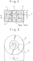
- Fig. 2 is an axial cross-sectional view showing an example of the laminated arrangement of gas generating agent plate-shaped molded members used in the gas generator shown in Fig. 1.
- Fig. 3 is a transverse cross-sectional view taken along the line III-III in Fig. 2.
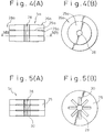
- Fig. 4 is a diagrammatic view showing another example of the laminated arrangement of the gas generating agent plate-shaped molded members, wherein Fig. 4(A) is an axial cross-sectional view, and Fig. 4(B) is a transverse cross-sectional view.
- Fig. 5 is a diagrammatic view showing still another example of the laminated arrangement of the gas generating agent plate-shaped molded members, wherein Fig. 5(A) is an axial cross-sectional view, and Fig. 5(B) is a transverse cross-sectional view.
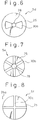
- Figs. 6 to 8 are transverse cross-sectional views showing further examples of the gas generating agent plate-shaped molded members.
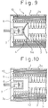
- Fig. 9 is a partial axial cross-sectional view of another embodiment of the gas generator of the present invention.
- Fig. 10 is a partial axial cross-sectional view of still another embodiment of the gas generator of the present invention.
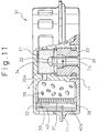
- Fig. 11 is an axial cross-sectional view showing an example of the gas generator to which the construction of the present invention can be applied.
- Fig. 1 is a cross-sectional illustration for explaining the construction of a gas generator 1 of the present invention.
- numeral 2 represents a container
- numeral 2c represents a gas outlet provided on a barrel surface 2a of the container 2
- numeral 3 represents a combustion chamber
- numeral 4 represents a combustion chamber gas outlet provided in the combustion chamber
- numeral 5 represents a gas generating agent plate-shaped (disk-shaped) molded member
- numeral 6 represents a holding member of the gas generating agent plate-shaped molded body
- numeral 7 represents an igniter
- numeral 8 represents a gas passing member
- numeral 9 represents an inner filter
- numeral 10 represents an outer filter
- numeral 11 represents a welding portion for welding the barrel surface 2a of the container 2 to an end surface 2b
- numeral 13 represents a gas passage
- character A represents a combustion gas flow (in the illustrated example, gas blows out from the combustion chamber gas outlet 4, passes through the gas passage 13 or the outer filter 10 in the circumferential direction, and emerge
- Numeral 20 represents an igniter cap
- numeral 21 represents an igniting agent
- numeral 22 represents a firing agent.
- a flame discharging hole 23 is formed in the center of the igniter cap 20, and the flame discharging hole 23 is usually sealed from the inside.
- a cushion member 24 is disposed between the holding member 6 (in this case, a coil spring is used for the holding member 6) and the gas generating agent 5 for preventing a surface of the gas generating agent 5 from being damaged. It is preferable that the cushion member 24 is made of ceramic paper.
- the gas passing member 8 may be made of any material through which gas can pass, and laminated meshes are preferably used.
- the inner filter 9 is disposed inside the combustion chamber for cooling a combustion gas flow and collecting the residue.
- rough laminated metallic meshes of 12 to 60# are usually used for the inner filter 9, or a press-formed member of metallic meshes can be used.
- the diameter and number of the combustion chamber outlets 4 provided in the gas combustion chamber are determined by the combustion characteristics of the gas generating agent 5, but it is designed such that the position of the combustion chamber gas outlets 4 do not overlap the gas outlets 2c formed in the container 2 so that the combustion gas discharged from the gas outlets 4 cannot directly rush to the outside of the container 2.
- the outer filter 10 comprises metallic meshes and a rolled ceramic filter.
- the metallic meshes are 20# to 100#
- the ceramic filter may be made of alumina silicate, and when necessary, sintered metallic nonwoven fabric may be used.
- Figure 2 is an axial cross-sectional view showing the laminated structure of the gas generating agent plate-shaped molded members 5 used in the gas generator shown in Fig. 1, and Fig. 3 is a transverse cross-sectional view taken along the line III-III in Fig. 2.
- the plate-shaped molded members 5 are formed in a doughnut-shape having a main gas passage hole 28 at the center thereof, and a close-contact surface 25 and a noncontact surface 26 are formed between the adjoining plate-shaped molded members, so that a recessed portion 29 is formed in the plate-shaped molded members on the side of the main gas passage hole 28.
- a recessed portion 29a is formed at the exterior side of the plate-shaped molded members 5a. Consequently, the close-contacting surface 25a is formed on the side of the main gas passage hole 28, and the noncontact surface 26a is formed facing the passage 28a for passing the main gas flowing outside of the plate-shaped molded member 5a.
- Recessed portions of the plate-shaped molded members shown in Figs. 2 to 4 are commonly formed in a ring-shape.
- the recessed portion may be formed in the form of a plurality of grooves 30 as shown in Fig. 5.
- the grooves 30 may be parallel, as shown in Fig. 5, or the grooves 30a may be formed in the form of a sector expanding from the main gas passage hole 28 to the outside, as shown in Fig. 6.
- the grooves 30b may penetrate through the gas generating agent from the main gas passage hole 28 to the outside, as shown in Fig. 7. Further, as shown in Fig. 8, only grooves 30c crossing each other may be formed, without a specially provided main gas passage hole 28.
- the plate-shaped molded members can be easily obtained by using a mold having a predetermined configuration, and pressing the gas generating agent metered to a predetermined amount with a pressing pressure of 1 to 3 t/cm2.
- the firing agent 22 When a firing current flows to the igniter 7, the firing agent 22 is burnt and the igniting agent 21 is then burnt. Then, hot gas and hot particles break a seal and flow into the combustion chamber 3 through the flame outlet 23. by these hot gas and hot particles, a portion of the surface of the gas generating agent except for the close-contact portions 25 starts burning. At this time, the noncontact surfaces 26 (area Al) also burn, and the combustion gas flows through the outlet 27 (area Ap) to the central hole.
- a ratio of Al/Ap is high at this time, that is, when the outlet area is smaller than the combustion area of the noncontact surface (usually, the ratio of Al/Ap is not less than 10, and preferably, it is in the range from 20 to 200), the pressure Pl in the noncontact surfaces 26 becomes higher than the pressure Po in the central hole 28. Therefore, a force (F) acts so as to separate the close-contact surfaces of the gas generating agent molded bodies.
- This force F is very weak under the condition of Al/Ap ⁇ 10, may be too weak even under the condition of Al/Ap ⁇ 20.
- the ratio of Al/Ap exceeds 200, the width of the noncontact surfaces becomes too narrow, so that the manufacture of the molded members may become difficult.
- the holding member overcomes this force F at the beginning of combustion, but in the case where the holding force of the holding member is reduced by the influence of heat of the generated gas, or in the case where the force F is very strong, a plurality of plate-shaped molded members are successively peeled one by one from the end of the agent, so that the surfaces of the close-contact portions start burning and so the burning area is successively increased to increase the gas generating speed. Accordingly, it is necessary to provide a space in which the molded members can be moved in the combustion chamber.
- the space B in which the gas generating agent plate-shaped molded members can be moved is determined in accordance with the number of the gas generating agent plate-shaped molded members to be charged in the container.
- the space B is approximately 10 mm.
- the combustion area is successively increased as described above, the amount of generated gas is increased, so that a gentle gas flow can be realized at the beginning of combustion.
- the combustion gas flows along the gas passage A shown in Fig. 1, and passes through the combustion chamber outlets 4. Then, the combustion gas passes through the outer filter 10, and is vented to the outside (the air bag) through the gas discharging holes 2c.
- the characteristics of the gas generator of the present invention reside in the provision of the recessed portions (or the provision of protruded portions) on the surface of the gas generating agent, to provide pressure unbalance portions so as to allow a plurality of the laminated plate-shaped molded members of the gas generating agent to be automatically peeled off one by one to increase the combustion area.
- the pressure exponent n of a gas generating agent mainly including NaN3 is usually in the range from 0.1 to 0.8, the pressure exponent being preferably not more than 0.6, and more preferably no more than 0.35.
- the inflater is usually provided with not only an environmental seal but also a pressure seal for sealing the combustion gas until the pressure is increased to a certain value at the beginning of ignition (due to this, a sufficient igniting operation can be conducted).
- This pressure seal is constructed to burst and release the combustion gas when the inflater pressure is increased to a predetermined value. It is effective to provide a plurality of pressure seals of different breakdown pressures (for example, Japanese Examined Patent Publication No. 63-1218), and when the pressure is increased, an additional pressure seal for high pressure use is activated so that the pressure is not increased to a predetermined value.
- Figure 9 shows an example in which the molded member holding member 6 of Fig. 1 is replaced by a concave disk-shaped perforated leaf spring.
- Fig. 10 shows an example in which a combustible substance molded member 12 is employed in the gas generator of Fig. 1. This combustible substance molded member 12 is fired by the igniter and produces particles at a high temperature so as to help the gas generating agent to be ignited, and to heat the holding member to reduce the holding force.
- any gas generating agent distributed for an air bag can be used without any limitation, but it is preferable to use a gas generating agent having a low pressure exponent, as described above.
- a gas generating agent having a low pressure exponent as described above.
- the combustible substance molded member any conventional substance can be used as long as the substance is provided with the aforesaid function.
- thermit type powder such as magnesium, Teflon and B/KNO3 may be used.
- a known metallic coil spring or a known leaf spring made of stainless steel, aluminum, shape memory alloy and iron may be used, in which resilience of the spring is lost when heated by the combustion gas (preferably at the temperature in the range from 120 to 1000°C).
- an aluminum mesh or a honeycomb may be used which fuses and loses its holding force when heated.
- the width h of the noncontact portions is 0.05 to 0.5 mm.
- the noncontact portions become identical to the close-contact portions, and in the case of a width wider than 0.5 mm, the force F becomes too weak.
- the design of the width of the noncontact portions may depend on the thickness or the diameter of the gas generating agent which will be determined by the combustion speed of the gas generating agent, but it is preferable that the width of the noncontact portions is below 20% of the thickness of the gas generating agent. Also, it is preferable that a ratio of the area of the noncontact portion to that of the entire overlapping portion (the total area of the close-contact and noncontact portions), is in the range from 5 to 70%.
- the holding force of the holding member for holding the gas generating agent molded members is in the range from 0.05 to 10 kg/cm2.
- the holding force is smaller than 0.05 kg/cm2 it is too weak and the molded members may be broken by vibration of the inflater.
- the holding force exceeds 10 kg/cm2 the close-contact portions are separated too late. Therefore, it is preferable that the diameter or the thickness of the holding member is not more than 5 mm. In the case where the diameter or the thickness of the holding member exceeds 5 mm, it takes too long to reduce the resilience of the holding member when heated.
- the container of this gas generator is made of aluminum or aluminum alloy.
- Aluminum alloy may preferably comprise Mg alloys (JIS 5083), Mg-Si alloys (JIS 6061) or Zn alloys (JIS 7075).
- the igniting agent charged in the igniter according to the present invention can be automatically fired at the temperature in the range from 150 to 300°C within 3 minutes to immediately fire the gas generating agent, prior to a time when a remarkably reduction in the strength of the container occurs and the aluminum container maintains a sufficient pressure durability in the event where the gas generator is put in a high temperature atmosphere of a fire.
- a preferable example of the igniting agent of the present invention having such a function is a powder composition comprising (A) a binder containing sulphur and (B) ammonium perchlorate.
- a binder containing sulphur component are, for example, polyorganic sulfide condensed from halide and alkali sulfide, polysulfide resin of ring-opening polymer of ring sulfide such as propylene sulfide, and sulphur polymer and prepolymer of sulphur polybutadiene.
- polysulfide resin of polyorganic sulfide which is a liquid polymer having a mercapto end group, and it is preferable that the molecular weight is approximately 1,000.
- the ammonium perchlorate component is preferably used for an igniting agent component in the case where the aluminum container is used. In this component, a phase transition of ammonium perchlorate occurs at the temperature of about 230°C at which the strength of aluminum is lowered.
- this component becomes unstable and tends to react to chemical treatments, however, at the temperature below 230°C, this component is very stable. From this viewpoint, this component is superior to cellulose nitrate used for an automatic firing agent in the above described United States Patent. Cellulose nitrate is inferior in a storage stability, and decomposition may occur with the lapse of time. Further, when the gas generating agent is ignited, the igniting capacity of the igniting agent component of the present invention is superior to that of cellulose nitrate, so that the composition itself can be used as an igniting agent. Also, when necessary, a (C) component of flammable metallic powder component may be added to the above described (A) and (B) components.
- the (C) component is preferably used for the (C) component.
- These elements can be used in any of the forms of simple substance of metal, alloy, intermetallic compound and mixture of them. It is preferable that the particle size of metallic powder is in the range from 1 to 50 ⁇ m.
- Al-Mg alloy and Zr-Ni alloy are preferably used for the alloy.
- ZrB and FeSi are preferably used for the intermetallic compound.
- a stabilizer, a hardening agent, a hardening accelerator, a tackifier (a flexible agent comprising, for example, an epoxy resin and a reaction accelerator), an epoxy resin, a plasticizer, a cross linking agent such as sulphur, and a decomposition catalyst for ammonium perchlorate such as a compound of Cr, Cu and Fe may be added to the firing agent.
- a general composition is described on page 93 of "Powder Handbook" published by Kyoritsu Shuppan Co. in Japan.
- the igniting agent used for the gas generator to accomplish the second object of the present invention is automatically fired at a relatively low temperature at which the aluminum container maintains a sufficient mechanical strength to endure the generated gas pressure.
- Mg-Teflon and B-KNO3 are used for the igniting agent and all of them are ignited at a temperature, above 400°C, at which the mechanical strength of an aluminum container is lowered so that it will burst and pieces of the broken container are scattered, leading to a very dangerous situation.
- the above described igniting agent which is ignited at a temperature from 150 to 300°C within 3 minutes is used.
- an igniting agent ignited at a temperature from 180 to 250°C is selected.
- the igniting agent of the present invention may be used as a low temperature automatic firing agent in the embodiment of United States Patent No. 4,561,675 and No. 4,858,951.
- the igniting agent of the present invention is provided at such a position that the igniting agent can be easily heated from the outside so that the igniting agent is sensitive to the outside heat, that is, it is preferable that a firing agent housing in which a firing agent is charged forms a portion of the gas generating agent container, or that the firing agent housing is in contact with the wall of the container, and in the case where a heat insulating layer is provided between the containers, that the thickness of the insulating layer is very small.
- the igniting agent itself is selected from a group of powders capable of being automatically ignited at a temperature at which the aluminum container can maintain a sufficient pressure durability to solve the serious problem of the explosion of the aluminum container is an original idea of the present inventor.
- Figure 11 is a cross-sectional view for explaining the construction of a gas generator 31 of the present invention.
- numeral 32 represents an aluminum container
- numeral 7a represents an igniter
- numeral 33 represents a holding member for holding the igniter
- numeral 34 represents a fuse used for ignition
- numeral 35 represents a gas generating agent (in this case, the gas generating agent is formed in a pellet-shape)
- numeral 36 represents a pin used for ignition
- numeral 37 represents an inner cylinder for dividing the combustion chamber (in this case, the inner cylinder comprises 2 parts for providing flexibility)
- numeral 38 represents a gas outlet provided in the inner cylinder (the gas outlet is sealed with a piece of aluminum foil before the gas generator is activated)
- numeral 39 represents an inner filter
- numeral 40a represents a lower filter (both filter 39 and 40a are formed of laminated metallic meshes of 8 tp 60# or pressed metallic meshes)
- numeral 40 represents an outer filter (the outer filter is composed of rolled
- the fuse 34 when a predetermined amount of current flows through the fuse 34, the fuse is heated and the firing agent 22 is ignited.
- the igniting agent 21 is then ignited, and a flame (hot gas and hot particles) from the igniting agent 21 passes through the flame outlet 41 to ignite the gas generating agent 35.
- the combustion gas (containing the residue) of the gas generating agent 35 has been cooled and filtered by the inner filter 39, it passes through the gas outlet 38, is cooled and minute residual particles are filtered by the lower and outer filters 40a and 40 and is discharged to the outside of the system.
- this gas generator 31 When this gas generator 31 is heated from the outside in the case of a fire, the igniting agent 21 of the present invention is heated by the heat transmitted through the aluminum container 32 and the igniter cap 20a, so that the igniting agent 21 is automatically ignited and breakage of the container is prevented.
- the igniting agent is important for the aluminum container of the present invention, and other articles such as the gas generating agent and the filter are not particularly limited.
- Binder Composition Polysulfide resin Lp33 (Chiokoru Co.) 100 weight parts Sulphur 1 Paraquinone dioxime (hardening agent) 7 Hardening assistant 5 Tackifier (flexible additive) 5 Igniting agent composition Ammonium perchlorate 64 weight parts Aluminum (particle size: 20 ⁇ m) 15 Binder composition 21
- the binder components are sufficiently mixed in advance.
- aluminum and ammonium perchlorate are added and mixed, and then grains of a predetermined shape are made.
- the grains are heated to about 80°C for 4 days. In this way, the igniting agent composition can be provided.
- inert grains such as grains of SiO2 may be added.
- This igniting agent having the weight of 1.5g was made granular, and charged into the aluminum gas generator of Fig. 11. Then the gas generator was put into a fire. The igniting agent was automatically fired, and the gas generator container was not broken.
- the aforesaid igniting agent may be applied to a gas generator having a structure shown in Fig. 1, wherein the container is made of aluminum.
- gas generation is gently conducted at the beginning of its operation, so that a vehicle occupant can be reliably protected from shock caused by a collision without being injured by the air bag that may otherwise suddenly rush out. Therefore, the gas generator is highly reliable.
- the gas generator to accomplish the second object of the present invention different from a type of gas generator in which a booster agent is mixed with an igniting agent, the igniting agent is positively heated when heat is transmitted from the outside, so that the igniting agent is automatically ignited at a predetermined temperature.
- the aluminum gas generator of the present invention when the aluminum gas generator of the present invention is employed, even when it is in a high temperature atmosphere in the case of a fire, it is possible to reliably avoid the danger in which the container may burst and pieces of the container scatter. Further, it is not necessary to provide additional parts and the number of assembling steps is not increased.
Abstract
Générateur de gaz (1) pour air-bag, comprenant un récipient (2) abritant une chambre de combustion (3) renfermant elle-même un agent générateur de gaz (5) et un dispositif de mise à feu (7). Une partie au moins dudit agent générateur de gaz est constituée d'une structure composée d'une multiplicité d'éléments lamellaires à recouvrement (5), et des saillies et des creux (29) sont ménagés sur chacun desdits éléments lamellaires, de manière à former une surface de contact étroit (25) et une surface de non contact (26) sur les surfaces de recouvrement de deux éléments lamellaires contigus. Des éléments de compression (6, 6a) maintiennent en les comprimant lesdites surfaces de contact (25) pour les empêcher de se séparer et, lorsque le récipient est en aliminium, un agent de mise à feu (21) entrant en fonction dans un délai de trois minutes dans une plage de températures comprise entre 150 et 300 °C, est contenu dans le dispositif de mise à feu (7).
Applications Claiming Priority (6)
| Application Number | Priority Date | Filing Date | Title |
|---|---|---|---|
| JP14478691 | 1991-06-17 | ||
| JP144786/91 | 1991-06-17 | ||
| JP163003/91 | 1991-07-03 | ||
| JP16300391 | 1991-07-03 | ||
| JP263715/91 | 1991-10-11 | ||
| JP26371591 | 1991-10-11 |
Publications (2)
| Publication Number | Publication Date |
|---|---|
| EP0589042A1 true EP0589042A1 (fr) | 1994-03-30 |
| EP0589042A4 EP0589042A4 (fr) | 1994-08-31 |
Family
ID=27318875
Family Applications (1)
| Application Number | Title | Priority Date | Filing Date |
|---|---|---|---|
| EP92913207A Withdrawn EP0589042A1 (fr) | 1991-06-17 | 1992-06-17 | Generateur de gaz pour air-bag |
Country Status (3)
| Country | Link |
|---|---|
| EP (1) | EP0589042A1 (fr) |
| CA (1) | CA2111690A1 (fr) |
| WO (1) | WO1992022440A1 (fr) |
Cited By (12)
| Publication number | Priority date | Publication date | Assignee | Title |
|---|---|---|---|---|
| EP0630783A1 (fr) * | 1993-06-22 | 1994-12-28 | Nippon Koki Co., Ltd. | Conteneur pour agent générateur de gaz d'un générateur de gaz de gonflage d'un coussin d'air |
| EP0635401A1 (fr) * | 1993-06-22 | 1995-01-25 | Nippon Koki Co., Ltd. | Générateur de gaz pour le gonflage d'un coussin d'air |
| EP0672562A1 (fr) * | 1994-03-14 | 1995-09-20 | Morton International, Inc. | Dispositif de précontrainte et de rattrapage de jeu du matériau générateur de gaz dans une installation de sac gonflable de véhicule |
| EP0694445A1 (fr) * | 1994-07-26 | 1996-01-31 | Morton International, Inc. | Gonfleur pour sac gonflable |
| WO1998003448A1 (fr) * | 1996-07-20 | 1998-01-29 | Dynamit Nobel Gmbh Explosivstoff- Und Systemtechnik | Fusible thermique |
| US5806887A (en) * | 1994-05-12 | 1998-09-15 | Sensor Technology Co., Ltd. | Gas generator with gas generant cushioning member and method of making thereof |
| EP1020333A1 (fr) * | 1996-04-08 | 2000-07-19 | Daicel Chemical Industries, Ltd. | Générateur de gaz pour coussin de sécurité gonflable et coussin de sécurité gonflable |
| US6183006B1 (en) | 1997-05-09 | 2001-02-06 | Daicel Chemical Industries, Ltd. | Gas generator for air bag and air bag system |
| US6406060B1 (en) | 1997-05-09 | 2002-06-18 | Daicel Chemical Industries, Ltd. | Gas generator for airbag and airbag system |
| US6453816B2 (en) | 1996-07-20 | 2002-09-24 | Dynamit Nobel Gmbh Explosivstoff-Und Systemtechnik | Temperature fuse with lower detonation point |
| EP1371936A3 (fr) * | 2002-06-14 | 2004-03-24 | Hirschmann Austria GmbH | Dispositif d'allumage pour un dispositif de sécurité |
| WO2011093477A1 (fr) * | 2010-01-28 | 2011-08-04 | Daicel Chemical Industries, Ltd. | Générateur de gaz |
Families Citing this family (2)
| Publication number | Priority date | Publication date | Assignee | Title |
|---|---|---|---|---|
| US5368329A (en) * | 1993-03-03 | 1994-11-29 | Morton International, Inc. | Dual stage inflator |
| US5585597A (en) * | 1995-05-15 | 1996-12-17 | Trw Vehicle Safety Systems Inc. | Air bag inflator |
Citations (6)
| Publication number | Priority date | Publication date | Assignee | Title |
|---|---|---|---|---|
| GB1231181A (fr) * | 1967-05-05 | 1971-05-12 | ||
| US3725154A (en) * | 1972-06-23 | 1973-04-03 | Us Navy | Mesa burning gas generator propellant |
| FR2207255A1 (fr) * | 1972-11-20 | 1974-06-14 | Aerojet General Co | |
| US4858951A (en) * | 1988-05-04 | 1989-08-22 | Trw Vehicle Safety Systems, Inc. | Igniter for gas generating material |
| JPH0288487A (ja) * | 1988-09-26 | 1990-03-28 | Toyoda Gosei Co Ltd | ガス発生剤成形体 |
| DE3923046A1 (de) * | 1989-07-13 | 1991-01-17 | Dynamit Nobel Ag | Ringtabletten fuer gasgeneratoren |
Family Cites Families (3)
| Publication number | Priority date | Publication date | Assignee | Title |
|---|---|---|---|---|
| US4817828A (en) * | 1986-10-03 | 1989-04-04 | Trw Automotive Products Inc. | Inflatable restraint system |
| US4938501A (en) * | 1989-03-10 | 1990-07-03 | Trw Vehicle Safety Systems Inc. | Inflator housing structure |
| JPH0375289A (ja) * | 1989-08-15 | 1991-03-29 | Nippon Koki Kk | エアバック展開用ガス発生装置の着火薬 |
-
1992
- 1992-06-17 CA CA002111690A patent/CA2111690A1/fr not_active Abandoned
- 1992-06-17 EP EP92913207A patent/EP0589042A1/fr not_active Withdrawn
- 1992-06-17 WO PCT/JP1992/000773 patent/WO1992022440A1/fr not_active Application Discontinuation
Patent Citations (6)
| Publication number | Priority date | Publication date | Assignee | Title |
|---|---|---|---|---|
| GB1231181A (fr) * | 1967-05-05 | 1971-05-12 | ||
| US3725154A (en) * | 1972-06-23 | 1973-04-03 | Us Navy | Mesa burning gas generator propellant |
| FR2207255A1 (fr) * | 1972-11-20 | 1974-06-14 | Aerojet General Co | |
| US4858951A (en) * | 1988-05-04 | 1989-08-22 | Trw Vehicle Safety Systems, Inc. | Igniter for gas generating material |
| JPH0288487A (ja) * | 1988-09-26 | 1990-03-28 | Toyoda Gosei Co Ltd | ガス発生剤成形体 |
| DE3923046A1 (de) * | 1989-07-13 | 1991-01-17 | Dynamit Nobel Ag | Ringtabletten fuer gasgeneratoren |
Non-Patent Citations (2)
| Title |
|---|
| PATENT ABSTRACTS OF JAPAN vol. 14, no. 284 (C-730) (4227) 20 June 1990 & JP-A-02 088 487 (TOYODA GOSEI CO LTD) 28 March 1990 * |
| See also references of WO9222440A1 * |
Cited By (22)
| Publication number | Priority date | Publication date | Assignee | Title |
|---|---|---|---|---|
| EP0635401A1 (fr) * | 1993-06-22 | 1995-01-25 | Nippon Koki Co., Ltd. | Générateur de gaz pour le gonflage d'un coussin d'air |
| EP0630783A1 (fr) * | 1993-06-22 | 1994-12-28 | Nippon Koki Co., Ltd. | Conteneur pour agent générateur de gaz d'un générateur de gaz de gonflage d'un coussin d'air |
| EP0672562A1 (fr) * | 1994-03-14 | 1995-09-20 | Morton International, Inc. | Dispositif de précontrainte et de rattrapage de jeu du matériau générateur de gaz dans une installation de sac gonflable de véhicule |
| US5806887A (en) * | 1994-05-12 | 1998-09-15 | Sensor Technology Co., Ltd. | Gas generator with gas generant cushioning member and method of making thereof |
| EP0694445A1 (fr) * | 1994-07-26 | 1996-01-31 | Morton International, Inc. | Gonfleur pour sac gonflable |
| US6234521B1 (en) | 1996-04-08 | 2001-05-22 | Daicel Chemical Industries, Ltd. | Airbag inflator and an airbag apparatus |
| US6409214B2 (en) | 1996-04-08 | 2002-06-25 | Daicel Chemical Industries, Ltd. | Airbag inflator and an airbag apparatus |
| US6695345B2 (en) | 1996-04-08 | 2004-02-24 | Daicel Chemical Industries, Ltd. | Airbag inflator and an airbag apparatus |
| US6196581B1 (en) | 1996-04-08 | 2001-03-06 | Daicel Chemical Industries, Ltd. | Airbag inflator and an airbag apparatus |
| EP1020333A1 (fr) * | 1996-04-08 | 2000-07-19 | Daicel Chemical Industries, Ltd. | Générateur de gaz pour coussin de sécurité gonflable et coussin de sécurité gonflable |
| US6453816B2 (en) | 1996-07-20 | 2002-09-24 | Dynamit Nobel Gmbh Explosivstoff-Und Systemtechnik | Temperature fuse with lower detonation point |
| WO1998003448A1 (fr) * | 1996-07-20 | 1998-01-29 | Dynamit Nobel Gmbh Explosivstoff- Und Systemtechnik | Fusible thermique |
| CZ299764B6 (cs) * | 1996-07-20 | 2008-11-19 | Delphi Technologies, Inc. | Systém pro výrobu plynu v generátoru plynu a použití tohoto systému |
| US6386582B2 (en) | 1997-05-09 | 2002-05-14 | Daicel Chemical Industries, Ltd. | Gas generator for air bag and air bag system |
| US6406060B1 (en) | 1997-05-09 | 2002-06-18 | Daicel Chemical Industries, Ltd. | Gas generator for airbag and airbag system |
| US6224096B1 (en) | 1997-05-09 | 2001-05-01 | Daicel Chemical Industries, Ltd. | Gas generator for air bag and air bag system |
| US6183006B1 (en) | 1997-05-09 | 2001-02-06 | Daicel Chemical Industries, Ltd. | Gas generator for air bag and air bag system |
| EP1371936A3 (fr) * | 2002-06-14 | 2004-03-24 | Hirschmann Austria GmbH | Dispositif d'allumage pour un dispositif de sécurité |
| WO2011093477A1 (fr) * | 2010-01-28 | 2011-08-04 | Daicel Chemical Industries, Ltd. | Générateur de gaz |
| CN102712289A (zh) * | 2010-01-28 | 2012-10-03 | 株式会社大赛璐 | 气体发生器 |
| US8342100B2 (en) | 2010-01-28 | 2013-01-01 | Daicel Chemical Industries, Ltd. | Gas generator |
| CN102712289B (zh) * | 2010-01-28 | 2015-02-18 | 株式会社大赛璐 | 气体发生器 |
Also Published As
| Publication number | Publication date |
|---|---|
| CA2111690A1 (fr) | 1992-12-18 |
| EP0589042A4 (fr) | 1994-08-31 |
| WO1992022440A1 (fr) | 1992-12-23 |
Similar Documents
| Publication | Publication Date | Title |
|---|---|---|
| US4530516A (en) | Aluminum inflator with steel center-tie | |
| US5845933A (en) | Airbag inflator with consumable igniter tube | |
| EP0369579B1 (fr) | Générateur de gaz à construction légère non soudé à lèvre roulée par centrifugation | |
| US4902036A (en) | Deflector ring for use with inflators with passive restraint devices | |
| EP1074433B1 (fr) | Générateur de gaz pour coussin de sécurité gonflable et coussin de sécurité gonflable | |
| KR900008585B1 (ko) | 가스발생기용 하우징(housing) 구조물 | |
| EP0509655B1 (fr) | Mélange de pastilles contenant de l'azoture et de petites particules siliciées tassées de façon compacte sans ségrégation, les petites particules entre les pastilles, et générateur de gaz | |
| US4547342A (en) | Light weight welded aluminum inflator | |
| EP0359408B1 (fr) | Ensemble de filtre pour dispositif gonfleur de construction non-soudée | |
| EP0069441B1 (fr) | Appareil pour accélérer le gonflage d'un sac à air basses températures | |
| CA2004550C (fr) | Generateur de gaz pour le gonflage des coussins d'air | |
| EP0589042A1 (fr) | Generateur de gaz pour air-bag | |
| EP2426015B1 (fr) | Générateur de gaz | |
| EP0359407A2 (fr) | Unité de gonfleur à construction légère, non-soudée pour sac à air dans des véhicules automobiles | |
| EP2383154B1 (fr) | Générateur de gaz | |
| JPH10181518A (ja) | 発火式熱ガス発生器とその製造方法 | |
| JPH0648880A (ja) | ガス発生器用の多層型ガス発生ディスク | |
| US20030146611A1 (en) | Adaptive output passenger disk inflator | |
| JPH0224242A (ja) | 車輌用受動拘束装置 | |
| US6129381A (en) | Gas Generator for air bag and air bag system | |
| JPWO2002083464A1 (ja) | ガス発生器 | |
| JPH05229397A (ja) | エアバッグ用ガス発生器 | |
| JPH0667711B2 (ja) | エアバック展開用ガス発生装置 | |
| JP2598813B2 (ja) | エアバック展開用ガス発生装置の燃焼室 | |
| WO2006105412A2 (fr) | Systeme generateur de gaz comprenant un dispositif d'auto-allumage |
Legal Events
| Date | Code | Title | Description |
|---|---|---|---|
| PUAI | Public reference made under article 153(3) epc to a published international application that has entered the european phase |
Free format text: ORIGINAL CODE: 0009012 |
|
| 17P | Request for examination filed |
Effective date: 19940110 |
|
| AK | Designated contracting states |
Kind code of ref document: A1 Designated state(s): DE ES FR GB IT |
|
| A4 | Supplementary search report drawn up and despatched | ||
| AK | Designated contracting states |
Kind code of ref document: A4 Designated state(s): DE ES FR GB IT |
|
| 17Q | First examination report despatched |
Effective date: 19950608 |
|
| STAA | Information on the status of an ep patent application or granted ep patent |
Free format text: STATUS: THE APPLICATION IS DEEMED TO BE WITHDRAWN |
|
| 18D | Application deemed to be withdrawn |
Effective date: 19960625 |