EP0588356B1 - Dispositif de remplissage de bouteilles ou de récipients similaires - Google Patents
Dispositif de remplissage de bouteilles ou de récipients similaires Download PDFInfo
- Publication number
- EP0588356B1 EP0588356B1 EP93114985A EP93114985A EP0588356B1 EP 0588356 B1 EP0588356 B1 EP 0588356B1 EP 93114985 A EP93114985 A EP 93114985A EP 93114985 A EP93114985 A EP 93114985A EP 0588356 B1 EP0588356 B1 EP 0588356B1
- Authority
- EP
- European Patent Office
- Prior art keywords
- gas
- filling
- gas path
- connection
- valve
- Prior art date
- Legal status (The legal status is an assumption and is not a legal conclusion. Google has not performed a legal analysis and makes no representation as to the accuracy of the status listed.)
- Expired - Lifetime
Links
Images

Classifications
-
- B—PERFORMING OPERATIONS; TRANSPORTING
- B67—OPENING, CLOSING OR CLEANING BOTTLES, JARS OR SIMILAR CONTAINERS; LIQUID HANDLING
- B67C—CLEANING, FILLING WITH LIQUIDS OR SEMILIQUIDS, OR EMPTYING, OF BOTTLES, JARS, CANS, CASKS, BARRELS, OR SIMILAR CONTAINERS, NOT OTHERWISE PROVIDED FOR; FUNNELS
- B67C3/00—Bottling liquids or semiliquids; Filling jars or cans with liquids or semiliquids using bottling or like apparatus; Filling casks or barrels with liquids or semiliquids
- B67C3/02—Bottling liquids or semiliquids; Filling jars or cans with liquids or semiliquids using bottling or like apparatus
- B67C3/22—Details
- B67C3/28—Flow-control devices, e.g. using valves
- B67C3/282—Flow-control devices, e.g. using valves related to filling level control
- B67C3/285—Flow-control devices, e.g. using valves related to filling level control using liquid contact sensing means
-
- B—PERFORMING OPERATIONS; TRANSPORTING
- B67—OPENING, CLOSING OR CLEANING BOTTLES, JARS OR SIMILAR CONTAINERS; LIQUID HANDLING
- B67C—CLEANING, FILLING WITH LIQUIDS OR SEMILIQUIDS, OR EMPTYING, OF BOTTLES, JARS, CANS, CASKS, BARRELS, OR SIMILAR CONTAINERS, NOT OTHERWISE PROVIDED FOR; FUNNELS
- B67C3/00—Bottling liquids or semiliquids; Filling jars or cans with liquids or semiliquids using bottling or like apparatus; Filling casks or barrels with liquids or semiliquids
- B67C3/02—Bottling liquids or semiliquids; Filling jars or cans with liquids or semiliquids using bottling or like apparatus
- B67C3/06—Bottling liquids or semiliquids; Filling jars or cans with liquids or semiliquids using bottling or like apparatus using counterpressure, i.e. filling while the container is under pressure
- B67C3/12—Pressure-control devices
-
- B—PERFORMING OPERATIONS; TRANSPORTING
- B67—OPENING, CLOSING OR CLEANING BOTTLES, JARS OR SIMILAR CONTAINERS; LIQUID HANDLING
- B67C—CLEANING, FILLING WITH LIQUIDS OR SEMILIQUIDS, OR EMPTYING, OF BOTTLES, JARS, CANS, CASKS, BARRELS, OR SIMILAR CONTAINERS, NOT OTHERWISE PROVIDED FOR; FUNNELS
- B67C3/00—Bottling liquids or semiliquids; Filling jars or cans with liquids or semiliquids using bottling or like apparatus; Filling casks or barrels with liquids or semiliquids
- B67C3/02—Bottling liquids or semiliquids; Filling jars or cans with liquids or semiliquids using bottling or like apparatus
- B67C3/22—Details
- B67C3/28—Flow-control devices, e.g. using valves
- B67C3/286—Flow-control devices, e.g. using valves related to flow rate control, i.e. controlling slow and fast filling phases
Definitions
- the invention relates to a device for filling bottles or the like.
- Containers A device of this type is known (DE-PS 16 32 004).
- the first gas path is connected on the one hand to a gas space which is formed above the filling level in the interior of an annular bowl of a filling machine which is not completely filled with the liquid filling content and on the other hand is controlled by a control valve via the control valve Interior of the first gas channel leading to be filled bottle connected.
- the latter is formed in a gas pipe or tubular shaft which carries the valve body of the liquid valve.
- the container to be filled is pretensioned via the gas path and the aforementioned gas channel.
- a second gas path is also provided, which leads into a return gas or residual gas chamber which is common to all filling elements of the filling machine and which is connected to the atmosphere via a nozzle or throttle. Furthermore, this second gas path is permanently connected to a second gas channel, which is also formed in the tubular shaft of the valve body and is open at the lower end of this shaft projecting above the valve body. The second gas channel encloses a fill level-determining probe provided in the shaft.
- control valve Although only a single control valve is provided in this known device for controlling the gas paths, this device has certain disadvantages. Thus, in addition to the need for two separate gas channels in the stem of the valve body, it also has a relatively complex construction. A further disadvantage is that a common actuating device is provided for the control valve and the liquid valve, which greatly increases the possibility of different controls or control methods is restricted. Furthermore, the functional elements of the control valve and especially the valve body of this control valve are difficult to access.
- the invention has for its object to develop a device of the above type in such a way that it avoids the disadvantages while maintaining the basic advantages of the known device, in particular. It also provides improved control options with a simplified construction.
- the gas paths or the supply and discharge of the compressed gas into or out of the container are at least for the pretensioning, for the counter pressure filling (preferably including slow filling, quick filling and / or braking and correction filling) as well as for relieving (preferably including Calming phase and / or pre-relief phase) fully controllable.
- the device according to the invention can be designed such that the control valve with all its functional elements remains accessible from the outside without difficulty, that is to say can also be easily replaced in the event of a repair.
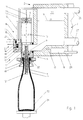
- 1 is a filling element which, together with further, similar filling elements 1, is provided on the circumference of a rotor part 3 which rotates around a vertical machine axis and forms an annular bowl 2.
- the filling element 1 essentially consists of a housing 4 fastened to the rotor 3, in which a liquid channel 5 is formed. This is connected in its upper region to the ring bowl 2 and forms with its lower region an annular discharge opening 7 for a liquid tube which surrounds a gas pipe 6.
- the liquid valve 8 is also provided, which in the usual way has a valve body 9 which interacts with a valve seat formed in the interior of the liquid channel.
- the valve body 9 is in the illustrated embodiment on the in its axis in the vertical direction and parallel to the machine axis arranged, provided on the underside of the filling element 1 and the housing 4 projecting gas pipe 6.
- Fig. 1 the liquid valve is shown in the closed position.
- a pneumatic actuating device is actuated to release the liquid valve 8.
- This actuating device which acts on the part of the gas pipe 6 extending above the valve body 9, contains, for example, a piston as an actuating element, but preferably a membrane, which is indicated schematically in FIG. 1 at 10 by broken lines.
- a fill-level-determining probe 11 is provided, which is enclosed by the gas tube 6 at a distance, so that there is a gas channel 12 within the gas tube 6, which is ring-shaped around the probe 11 and is open at the lower end of the gas tube 6.
- the gas channel 12 opens into a chamber 13 formed in the housing 4 and closed to the outside.
- a valve housing 14 On the radially outer side of the housing 4 with respect to the machine axis, a valve housing 14 is provided there, which forms a chamber 15 which is closed towards the outside. The latter is permanently connected to the chamber 13 via a line or a channel 16 '. The channel 16 'forms a gas path 16 together with the gas channel 12. Furthermore, the chamber 15 is located via a gas path 17 running partly in the valve housing 14, partly in the housing 4 and partly in the rotor part 3, with a gas path 17 provided in the rotor part 3 and common to all filling elements 1 Return gas channel 18 in constant communication.
- a throttle or nozzle 19 is provided in the part of the gas path 17 formed in the valve housing 14. Parallel to the nozzle 19, the gas path 17 forms a bypass in which a check valve 20 is arranged.
- This check valve 20, which in the embodiment shown consists of a ball forming the valve body and a spring, is designed such that it opens in a flow direction out of the gas path 17 into the chamber 15 and prevents a flow in
- the chamber 15 is also connected via a third gas path 21, which is formed by a line or a channel, to a gas space 22 which is in the ring vessel 2, which is not completely filled with the liquid filling material, but only up to a predetermined level N above the filling material level is formed.
- the connection between the gas path 21 and the chamber 15 is controlled by a control valve 23 which, in the non-actuated state shown in FIG. 1, closes the gas path 21 at the junction with the chamber 15 with its valve body 24.
- the control valve 23 can be actuated pneumatically and has a pneumatic actuation device 25.
- FIG. 1 also shows various lines, specifically a line 26 leading into the gas space 22, via which compressed gas is supplied to this gas space in a controlled manner, in such a way that a predetermined pressure is maintained in the gas space 22.
- the liquid filling material is fed to the ring bowl 2 via the line 27, specifically controlled in such a way that a desired level N of the filling material level is maintained (within a predetermined fluctuation range).
- the gas pipe has an opening 6 ′ for the gas channel 12 above its lower end, the cross section of which is smaller than the cross section of the gas channel 12.
- the peculiarity of the filler element 1 described above is that only a single, very simple valve, namely the control valve 23, is sufficient to control the gas paths, which only has two operating states, namely an open state and a closed state. In the embodiment shown, only the control valve 23 and the liquid valve 8 have to be actuated to fill the bottle.
- the control valve 23 is opened by the actuating device 25, so that compressed gas, which in the embodiment shown is sterile air, into the gas path 21, which is now connected to the chamber 15 Chamber 15 and via the gas path 16 and the gas channel 12 into the interior of the bottle 32.
- compressed gas which in the embodiment shown is sterile air
- the bottle 32 is thus biased to a pressure corresponding to the pressure in the gas space 22 via the gas pipe 6 protruding into the interior through the bottle mouth.
- a small amount of pressurized gas also reaches the residual gas duct 18 via the gas path 17. However, by selecting the nozzle 19 accordingly, it is ensured that this amount of pressurized gas is small.
- the control valve 23 is closed again and the liquid valve 8 is opened so that the liquid filling material flows into the interior of the bottle 32 via the discharge opening 7. That out here Compressed or return gas displaced from the interior of the bottle 32 flows via the gas channel 12 and the gas paths 16 and 17 into the return gas chamber 18.
- the nozzle 19 provides for a corresponding throttling of the displaced gas flow and thus for a gentle and slow filling speed.
- the filling speed actually achieved results from the cross section of the nozzle 19 and the difference between the pressure in the gas space 22 and in the residual gas duct 18. Both parameters can be changed or set depending on the sensitivity of the filling material (beverage) to be filled.
- the time for this slow filling is usually only a few 100 milliseconds.
- the bottle 32 is filled after its slow filling in its less critical middle area with a high inflow rate.
- the control valve 23 is opened so that there is then an additional connection to the gas space 22 via the gas path 21, via which an additional, unthrottled gas flow of the gas displaced during filling can be discharged.
- the filling speed in this rapid filling phase is essentially determined by the level N in the ring bowl. Via the level control, the level of level N, i.e. these parameters can be adapted to the respective special requirements (e.g. filling properties of the filling material and / or shape of the bottle 32 to be filled, etc.).
- the control valve 23 is closed again via the actuating device 25, and thus the connection via the gas path 21 to the gas space 22 is interrupted.
- the filling speed is thereby reduced to the value of the filling phase.
- the level of the filling material now rises at a low speed. Small bubbles that go through during the quick fill phase Flow turbulences that were held in suspension rise to the surface.
- the product level reaches the probe 11 arranged in the gas pipe 6 with a uniform surface appearance and free of bubbles.
- the product level which is at a standstill in the braking phase, enables the level to be measured precisely.
- the liquid valve 8 is closed, preferably for a correction filling with a time delay generated, for example, by a control electronics, with which a filling level correction in the range of approximately 10-20 mm is then possible.
- control valve 23 is briefly opened once or several times, so that the filling pressure which corresponds to the pressure in the gas space 22 is maintained in the bottle 32.
- the pressure in the neck of the filled bottle 32 begins to decrease via the nozzle 19 provided in the gas path 17 to the pressure which is set in the residual gas channel 18.
- this relief process or the pre-relief pressure can be adapted to the properties of the respective filling material.
- the corresponding relief cycles, In other words, the opening times can be variably preselected as a time function via the control electronics, regardless of the filler speed.
- the pressure inside the bottle 32 builds up via the nozzle 19 to the pressure prevailing in the residual gas channel 18, which is, for example, between 0.5 and 1.0 bar.
- the pressure regulated in the residual gas channel 18 is maintained in the bottle interior until the bottle 32 is pulled off.
- the bottle 32 is then finally pulled off with a slight excess pressure in the interior of the bottle, with no spraying losses. Since the gas pipe 6 has an opening 6 ', through which the gas channel 12 is connected to the interior of the bottle 32 in the area of the bottle mouth, there is no expansion shock from the gas pipe 6 which disturbs the liquid filling material when the bottle is pulled off.
- An additional relief valve can be used to avoid pulling off with a slight overpressure.
- CIP cleaning is also possible with the filling element 1, as shown in FIG. 2.
- a cap 32 is provided on the underside of the filling element 1, which forms a flushing space which receives the gas pipe 6 and which is sealed off from the outside by a seal 35 of the cap 34, by the centering tulip 30 and its seal 33.
- the cleaning medium used for CIP cleaning is supplied to the residual gas channel 18 with an overpressure, for example with an overpressure of 3.0 to 4.0 bar.
- an overpressure for example with an overpressure of 3.0 to 4.0 bar.
- the cleaning medium enters the chamber 15 and from there flows through the gas path 16 with the return gas channel 12.
- the cleaning medium emerging from the gas pipe 6 into the cap 34 passes through the opened liquid valve 8 in the ring bowl 2, which forms the return of the cleaning medium.
- the cleaning is carried out in such a way that the cleaning medium initially has a pressure which is not yet sufficient to open the check valve 20, and that this pressure then increases to the pressure required to open the check valve. This ensures that the nozzle 19 is rinsed or cleaned sufficiently in any case. If the control valve 23 is open, the cleaning medium also flows through the gas path 21.
- the residual gas channel 18 it is possible for the residual gas channel 18 to communicate with the atmosphere via an opening or nozzle or for the gas path 17 to lead directly to the atmosphere via such an opening or nozzle.
Claims (13)
- Dispositif de remplissage de bouteilles ou de récipients similaires au moyen d'un produit liquide de remplissage comportant au moins un élément ou tête de remplissage (1) doté d'une valve pour liquide (8), ainsi que des passages pour gaz (16, 17, 21) formés au moins partiellement dans l'élément de remplissage (1), qui sont chacun, au cours du remplissage, en communication par l'intermédiaire d'un dispositif de raccordement, avec l'espace intérieur du récipient (32), et dont un premier passage pour gaz (21) est raccordé à un premier espace (22) livrant passage à un gaz sous pression, mis sous une première pression, appartenant à un récipient (2) destiné au produit de remplissage, et dont un deuxième passage pour gaz (17) sert à l'évacuation du gaz sous pression, jusque dans une zone dans laquelle règne une deuxième pression inférieure à la première pression, dispositif comportant également une valve de commande (23) qui peut être commandée entre une position d'ouverture et une position de fermeture, et par l'intermédiaire de laquelle peut être commandé le premier passage pour gaz (21), ou la communication de celui-ci avec le dispositif de raccordement conduisant à l'espace intérieur du récipient (32), tandis que le deuxième passage pour gaz (17) est en permanence en communication avec le dispositif de raccordement conduisant à l'espace intérieur du récipient (32), caractérisé en ce que pour le premier et pour le deuxième passage pour gaz (21, 17), est prévu un dispositif de raccordement commun qui est formé par un troisième passage pour gaz (16) qui sert aussi bien à amener qu'à évacuer le gaz sous pression dans le récipient (32), et respectivement hors du récipient (32), et en ce que pour la valve de commande (23) et pour la valve (8) pour liquides sont prévus des dispositifs d'actionnement séparés (25, 10).
- Dispositif selon la revendication 1, caractérisé en ce que les deuxième et troisième passages pour gaz (17, 16) sont en communication entre eux de façon permanente, c'est-à-dire non commandée.
- Dispositif selon la revendication 1 ou 2, caractérisé en ce que, pour la valve de commande (23), un accès facile est prévu, sur un côté extérieur de l'élément de remplissage (1) ou d'un corps (4) de cet élément de remplissage.
- Dispositif selon l'une des revendications 1 à 3, caractérisé en ce que dans le deuxième passage pour gaz (17) est prévu au moins une buse ou valve d'étranglement (19) déterminant la section transversale d'écoulement efficace de ce passage pour gaz.
- Dispositif selon la revendication 4, caractérisé en ce que dans le deuxième passage pour gaz (17) est prévue au moins une valve anti-retour (20) montée en parallèle par rapport à la buse (19), au nombre d'au moins une, qui s'ouvre dans un sens d'écoulement et qui s'étend dans le deuxième passage pour gaz (17) dans une direction le mettant en communication avec le troisième passage pour gaz (16) et/ou avec le premier passage pour gaz (21).
- Dispositif selon l'une des revendications précédentes, caractérisé en ce que les passages pour gaz (16, 17, 21) débouchent dans une chambre (15) commune.
- Dispositif selon la revendication 6, caractérisé en ce qu'un corps (24) de la valve de commande (23) est prévu dans la chambre (15) commune.
- Dispositif selon l'une des revendications 1 à 7, caractérisé en ce que le premier passage pour gaz (21) est en communication avec une chambre pour gaz sous pression ou un espace pour gaz (22) d'un récipient (2) qui n'est que partiellement rempli de produit liquide de remplissage.
- Dispositif selon l'une des revendications 1 à 8, caractérisé en ce que le deuxième passage pour gaz (17) est en communication avec l'atmosphère.
- Dispositif selon l'une des revendications 1 à 8, caractérisé en ce que le deuxième passage pour gaz (17) est en communication avec un canal (18) pour gaz de reflux ou gaz résiduel.
- Dispositif selon l'une des revendications 1 à 10, caractérisé en ce qu'il comporte des moyens destinés au maintien d'une valeur fixée à l'avance en ce qui concerne la deuxième pression, de préférence au maintien d'une pression fixée à l'avance dans le canal (18) pour gaz résiduel ou gaz de reflux.
- Dispositif selon l'une des revendications 1 à 11, caractérisé en ce que le troisième passage pour gaz (16) comprend un canal pour gaz (12) formé dans un tube (6) pour gaz de l'élément de remplissage et entourant de préférence une sonde (11) déterminant les hauteurs de remplissage.
- Dispositif selon la revendication 12, caractérisé en ce que le tube (6) pour gaz présente, au-dessus de son extrémité inférieure, une ouverture supplémentaire (6') destinée au canal pour gaz (12).
Applications Claiming Priority (2)
| Application Number | Priority Date | Filing Date | Title |
|---|---|---|---|
| DE4231114 | 1992-09-17 | ||
| DE4231114A DE4231114A1 (de) | 1992-09-17 | 1992-09-17 | Vorrichtung zum Füllen von Flaschen o. dgl. Behältern |
Publications (2)
| Publication Number | Publication Date |
|---|---|
| EP0588356A1 EP0588356A1 (fr) | 1994-03-23 |
| EP0588356B1 true EP0588356B1 (fr) | 1995-12-06 |
Family
ID=6468179
Family Applications (1)
| Application Number | Title | Priority Date | Filing Date |
|---|---|---|---|
| EP93114985A Expired - Lifetime EP0588356B1 (fr) | 1992-09-17 | 1993-09-17 | Dispositif de remplissage de bouteilles ou de récipients similaires |
Country Status (5)
| Country | Link |
|---|---|
| US (1) | US5402833A (fr) |
| EP (1) | EP0588356B1 (fr) |
| AT (1) | ATE131135T1 (fr) |
| DE (2) | DE4231114A1 (fr) |
| ES (1) | ES2080569T3 (fr) |
Cited By (1)
| Publication number | Priority date | Publication date | Assignee | Title |
|---|---|---|---|---|
| DE102022102540A1 (de) | 2022-02-03 | 2023-08-03 | Khs Gmbh | Füllmaschine sowie Verfahren zum Füllen mit Behältern mittels einer Füllmaschine |
Families Citing this family (14)
| Publication number | Priority date | Publication date | Assignee | Title |
|---|---|---|---|---|
| US6338370B1 (en) | 2000-05-31 | 2002-01-15 | Fogg Filler Company | Fill valve assembly for filler device and associated method |
| US7040075B2 (en) | 2001-08-08 | 2006-05-09 | The Clorox Company | Nitrogen cap chute end |
| US6786248B2 (en) | 2001-10-11 | 2004-09-07 | Fogg Filler Company | Fill valve assembly for filler device |
| US6889482B2 (en) | 2002-10-10 | 2005-05-10 | Fogg Filler Company | Filler device sub-assembly |
| DE102007022259A1 (de) * | 2007-05-09 | 2009-01-15 | Khs Ag | Füllsystem sowie Verfahren zum Steuern eines Füllsystems |
| US8915270B2 (en) | 2009-10-05 | 2014-12-23 | Fogg Filler Company | Filler device having an enclosure sub-assembly |
| CN101746701B (zh) * | 2010-01-14 | 2011-05-11 | 安丘市鼎正机械设备有限公司 | 变流速智能感应灌装阀 |
| DE102010024522A1 (de) * | 2010-06-21 | 2011-12-22 | Khs Gmbh | Verfahren sowie Füllelement zum Druckfüllen von Behältern mit einem flüssigen Füllgut |
| DE102010027512A1 (de) * | 2010-07-16 | 2012-01-19 | Khs Gmbh | Füllelement, Verfahren sowie Füllsystem zum Füllen von Behältern |
| US10597277B2 (en) | 2011-07-08 | 2020-03-24 | Fogg Filler Company | Fill valve assembly for filler device and associated method of use |
| DE102011116469A1 (de) * | 2011-10-20 | 2013-04-25 | Khs Gmbh | Verfahren sowie Füllmaschine zum Füllen von Flaschen oder dgl. Behältern (2) mit einem flüssigen Füllgut |
| DE102011120164A1 (de) * | 2011-12-06 | 2013-06-06 | Khs Gmbh | Füllelement sowie Füllsystem |
| DE102014109589A1 (de) * | 2014-07-09 | 2016-01-14 | Khs Gmbh | Füllsystem zum Füllen von Flaschen oder dergleichen Behältern |
| CN109592623A (zh) * | 2019-02-02 | 2019-04-09 | 长沙康欧创新科技有限公司 | 一种液体灌装机 |
Family Cites Families (9)
| Publication number | Priority date | Publication date | Assignee | Title |
|---|---|---|---|---|
| DE1607996A1 (de) * | 1967-07-22 | 1972-03-02 | Seitz Werke Gmbh | Fuellelement fuer Gegendruckfuellmaschine |
| DE1632004C3 (de) * | 1967-12-16 | 1975-11-20 | Seitz-Werke Gmbh, 6550 Bad Kreuznach | Füllelement für Ein- oder Mehrkammer-Gegendruckfüllmaschinen |
| DE2234120C3 (de) * | 1972-07-12 | 1979-08-09 | Seitz-Werke Gmbh, 6550 Bad Kreuznach | Füllelement mit langem Fallrohr für Mehrkammer-Gegendruckfüllmaschinen |
| US4201249A (en) * | 1977-10-11 | 1980-05-06 | Holstein Und Kappert Gmbh | Machine for the filling of liquids into containers |
| DE3024099A1 (de) * | 1980-06-27 | 1982-01-21 | Seitz-Werke Gmbh, 6550 Bad Kreuznach | Verfahren und vorrichtung zur rueckgewinnung eines inerten gases |
| DE3717256A1 (de) * | 1987-05-22 | 1988-12-01 | Seitz Enzinger Noll Masch | Verfahren und vorrichtung zum fuellen von kohlensaeurehaltigen fluessigkeiten, insbesondere getraenken, unter gegendruck in gefaesse od. dgl. |
| DE3807046A1 (de) * | 1988-03-04 | 1989-10-12 | Seitz Enzinger Noll Masch | Verfahren und vorrichtung zum abfuellen von kohlensaeurehaltigen fluessigkeiten, insbesondere getraenken, unter gegendruck in gefaesse oder dgl. |
| DE3809852A1 (de) * | 1988-03-24 | 1989-10-05 | Seitz Enzinger Noll Masch | Verfahren zum aseptischen bzw. sterilen abfuellen von fluessigem fuellgut in behaelter sowie vorrichtung zum durchfuehren dieses verfahrens |
| DE3825093C2 (de) * | 1988-07-23 | 1994-01-13 | Kronseder Maschf Krones | Verfahren und Vorrichtung zum Füllen von Flaschen oder dgl. in Gegendruckfüllmaschinen |
-
1992
- 1992-09-17 DE DE4231114A patent/DE4231114A1/de not_active Withdrawn
-
1993
- 1993-09-17 AT AT93114985T patent/ATE131135T1/de not_active IP Right Cessation
- 1993-09-17 EP EP93114985A patent/EP0588356B1/fr not_active Expired - Lifetime
- 1993-09-17 US US08/123,005 patent/US5402833A/en not_active Expired - Lifetime
- 1993-09-17 DE DE59301094T patent/DE59301094D1/de not_active Expired - Fee Related
- 1993-09-17 ES ES93114985T patent/ES2080569T3/es not_active Expired - Lifetime
Cited By (1)
| Publication number | Priority date | Publication date | Assignee | Title |
|---|---|---|---|---|
| DE102022102540A1 (de) | 2022-02-03 | 2023-08-03 | Khs Gmbh | Füllmaschine sowie Verfahren zum Füllen mit Behältern mittels einer Füllmaschine |
Also Published As
| Publication number | Publication date |
|---|---|
| US5402833A (en) | 1995-04-04 |
| ES2080569T3 (es) | 1996-02-01 |
| DE59301094D1 (de) | 1996-01-18 |
| EP0588356A1 (fr) | 1994-03-23 |
| ATE131135T1 (de) | 1995-12-15 |
| DE4231114A1 (de) | 1994-03-24 |
Similar Documents
| Publication | Publication Date | Title |
|---|---|---|
| EP0697369B1 (fr) | Procédé pour remplir des bouteilles ou analogues au moyen d'un liquide | |
| EP0588356B1 (fr) | Dispositif de remplissage de bouteilles ou de récipients similaires | |
| DE10359492B3 (de) | Füllelement für eine Füllmaschine | |
| EP0582190B1 (fr) | Dispositif de remplissage de bouteilles ou de récipients analogues | |
| EP2029469B1 (fr) | Élément de remplissage et machine de remplissage munie d'éléments de remplissage de ce type | |
| EP0953542B1 (fr) | Vanne de remplissage pour une machine de remplissage | |
| EP0331137B1 (fr) | Procédé et dispositif de remplissage, sous contre-pression, de récipients avec des liquides carbonatés, en particulier des boissons | |
| DE3825093A1 (de) | Verfahren und vorrichtung zum fuellen von flaschen oder dergl. in gegendruckfuellmaschinen | |
| WO2014183827A1 (fr) | Système et machine de remplissage de récipients | |
| EP1660402A1 (fr) | Dispositif et procede de remplissage a contre-pression | |
| DE823263C (de) | Steuerkopf fuer Vorrichtungen zum Abfuellen gashaltiger oder nicht gashaltiger Fluessigkeiten | |
| DE2002060A1 (de) | Fuellrohrloses Fuellelement fuer Gegendruck-Fuellmaschinen in Ein- oder Mehrkammer-Bauweise | |
| DE4402980C1 (de) | Füllsystem zum Abfüllen eines flüssigen Füllgutes in Flaschen, Dosen oder dgl. Behälter | |
| EP0705788B1 (fr) | Procédé pour remplir des bouteilles ou des récipients similaires avec un produit liquide | |
| DE4342142C2 (de) | Vorrichtung zum Füllen von Flaschen oder dergl. Behälter mit einem flüssigen Füllgut | |
| DE2947035C2 (de) | Füllelement für Gegendruck-Gefäßfüllmaschine | |
| DE4324592C1 (de) | Verfahren und Vorrichtung zum Einfüllen einer Flüssigkeit in Gefäße | |
| DE102016105552A1 (de) | Füllventil zum Befüllen eines Behälters mit einem Füllprodukt | |
| EP2576420B1 (fr) | Élément de remplissage et machine de remplissage pour le remplissage de bouteilles ou de récipients analogues | |
| DE4201698A1 (de) | Verfahren zum fuellen von flaschen o. dgl. behaelter mit einem fluessigen fuellgut sowie vorrichtung zum durchfuehren dieses verfahrens | |
| EP0308723B1 (fr) | Organe de remplissage pour installation d'embouteillage de boissons | |
| DE4323746A1 (de) | Verfahren und Vorrichtung zur Beeinflussung der Füllmenge beim Abfüllen von Flüssigkeiten in Flaschen | |
| EP0416473B1 (fr) | Tête de remplissage pour embouteilleuse à contre-pression | |
| WO2007104327A1 (fr) | Dispositif d'émission pour un produit fluide et dispositif de distribution comportant un tel dispositif d'émission | |
| EP0379102A1 (fr) | Dispositif pour le remplissage dosé d'un matériau de remplissage liquide ou pâteux dans des récipients |
Legal Events
| Date | Code | Title | Description |
|---|---|---|---|
| PUAI | Public reference made under article 153(3) epc to a published international application that has entered the european phase |
Free format text: ORIGINAL CODE: 0009012 |
|
| AK | Designated contracting states |
Kind code of ref document: A1 Designated state(s): AT BE DE ES FR GB IT NL |
|
| 17P | Request for examination filed |
Effective date: 19940816 |
|
| 17Q | First examination report despatched |
Effective date: 19950222 |
|
| ITF | It: translation for a ep patent filed |
Owner name: BARZANO' E ZANARDO ROMA S.P.A. |
|
| GRAA | (expected) grant |
Free format text: ORIGINAL CODE: 0009210 |
|
| AK | Designated contracting states |
Kind code of ref document: B1 Designated state(s): AT BE DE ES FR GB IT NL |
|
| REF | Corresponds to: |
Ref document number: 131135 Country of ref document: AT Date of ref document: 19951215 Kind code of ref document: T |
|
| GBT | Gb: translation of ep patent filed (gb section 77(6)(a)/1977) |
Effective date: 19951218 |
|
| REF | Corresponds to: |
Ref document number: 59301094 Country of ref document: DE Date of ref document: 19960118 |
|
| ET | Fr: translation filed | ||
| REG | Reference to a national code |
Ref country code: ES Ref legal event code: FG2A Ref document number: 2080569 Country of ref document: ES Kind code of ref document: T3 |
|
| PG25 | Lapsed in a contracting state [announced via postgrant information from national office to epo] |
Ref country code: AT Effective date: 19960917 |
|
| PG25 | Lapsed in a contracting state [announced via postgrant information from national office to epo] |
Ref country code: ES Free format text: LAPSE BECAUSE OF NON-PAYMENT OF DUE FEES Effective date: 19960918 |
|
| PG25 | Lapsed in a contracting state [announced via postgrant information from national office to epo] |
Ref country code: BE Effective date: 19960930 |
|
| PLBE | No opposition filed within time limit |
Free format text: ORIGINAL CODE: 0009261 |
|
| STAA | Information on the status of an ep patent application or granted ep patent |
Free format text: STATUS: NO OPPOSITION FILED WITHIN TIME LIMIT |
|
| 26N | No opposition filed | ||
| BERE | Be: lapsed |
Owner name: KHS MASCHINEN- UND ANLAGENBAU A.G. Effective date: 19960930 |
|
| PG25 | Lapsed in a contracting state [announced via postgrant information from national office to epo] |
Ref country code: NL Free format text: LAPSE BECAUSE OF NON-PAYMENT OF DUE FEES Effective date: 19980401 |
|
| NLV4 | Nl: lapsed or anulled due to non-payment of the annual fee |
Effective date: 19980401 |
|
| PGFP | Annual fee paid to national office [announced via postgrant information from national office to epo] |
Ref country code: DE Payment date: 20010711 Year of fee payment: 9 |
|
| PGFP | Annual fee paid to national office [announced via postgrant information from national office to epo] |
Ref country code: GB Payment date: 20010914 Year of fee payment: 9 |
|
| PGFP | Annual fee paid to national office [announced via postgrant information from national office to epo] |
Ref country code: FR Payment date: 20010926 Year of fee payment: 9 |
|
| REG | Reference to a national code |
Ref country code: GB Ref legal event code: IF02 |
|
| PG25 | Lapsed in a contracting state [announced via postgrant information from national office to epo] |
Ref country code: GB Free format text: LAPSE BECAUSE OF NON-PAYMENT OF DUE FEES Effective date: 20020917 |
|
| PG25 | Lapsed in a contracting state [announced via postgrant information from national office to epo] |
Ref country code: DE Free format text: LAPSE BECAUSE OF NON-PAYMENT OF DUE FEES Effective date: 20030401 |
|
| GBPC | Gb: european patent ceased through non-payment of renewal fee |
Effective date: 20020917 |
|
| PG25 | Lapsed in a contracting state [announced via postgrant information from national office to epo] |
Ref country code: FR Free format text: LAPSE BECAUSE OF NON-PAYMENT OF DUE FEES Effective date: 20030603 |
|
| REG | Reference to a national code |
Ref country code: FR Ref legal event code: ST |
|
| REG | Reference to a national code |
Ref country code: ES Ref legal event code: FD2A Effective date: 19971011 |
|
| PG25 | Lapsed in a contracting state [announced via postgrant information from national office to epo] |
Ref country code: IT Free format text: LAPSE BECAUSE OF NON-PAYMENT OF DUE FEES;WARNING: LAPSES OF ITALIAN PATENTS WITH EFFECTIVE DATE BEFORE 2007 MAY HAVE OCCURRED AT ANY TIME BEFORE 2007. THE CORRECT EFFECTIVE DATE MAY BE DIFFERENT FROM THE ONE RECORDED. Effective date: 20050917 |