EP0588356B1 - Filling divice for bottles or like containers - Google Patents
Filling divice for bottles or like containers Download PDFInfo
- Publication number
- EP0588356B1 EP0588356B1 EP93114985A EP93114985A EP0588356B1 EP 0588356 B1 EP0588356 B1 EP 0588356B1 EP 93114985 A EP93114985 A EP 93114985A EP 93114985 A EP93114985 A EP 93114985A EP 0588356 B1 EP0588356 B1 EP 0588356B1
- Authority
- EP
- European Patent Office
- Prior art keywords
- gas
- filling
- gas path
- connection
- valve
- Prior art date
- Legal status (The legal status is an assumption and is not a legal conclusion. Google has not performed a legal analysis and makes no representation as to the accuracy of the status listed.)
- Expired - Lifetime
Links
Images

Classifications
-
- B—PERFORMING OPERATIONS; TRANSPORTING
- B67—OPENING, CLOSING OR CLEANING BOTTLES, JARS OR SIMILAR CONTAINERS; LIQUID HANDLING
- B67C—CLEANING, FILLING WITH LIQUIDS OR SEMILIQUIDS, OR EMPTYING, OF BOTTLES, JARS, CANS, CASKS, BARRELS, OR SIMILAR CONTAINERS, NOT OTHERWISE PROVIDED FOR; FUNNELS
- B67C3/00—Bottling liquids or semiliquids; Filling jars or cans with liquids or semiliquids using bottling or like apparatus; Filling casks or barrels with liquids or semiliquids
- B67C3/02—Bottling liquids or semiliquids; Filling jars or cans with liquids or semiliquids using bottling or like apparatus
- B67C3/22—Details
- B67C3/28—Flow-control devices, e.g. using valves
- B67C3/282—Flow-control devices, e.g. using valves related to filling level control
- B67C3/285—Flow-control devices, e.g. using valves related to filling level control using liquid contact sensing means
-
- B—PERFORMING OPERATIONS; TRANSPORTING
- B67—OPENING, CLOSING OR CLEANING BOTTLES, JARS OR SIMILAR CONTAINERS; LIQUID HANDLING
- B67C—CLEANING, FILLING WITH LIQUIDS OR SEMILIQUIDS, OR EMPTYING, OF BOTTLES, JARS, CANS, CASKS, BARRELS, OR SIMILAR CONTAINERS, NOT OTHERWISE PROVIDED FOR; FUNNELS
- B67C3/00—Bottling liquids or semiliquids; Filling jars or cans with liquids or semiliquids using bottling or like apparatus; Filling casks or barrels with liquids or semiliquids
- B67C3/02—Bottling liquids or semiliquids; Filling jars or cans with liquids or semiliquids using bottling or like apparatus
- B67C3/06—Bottling liquids or semiliquids; Filling jars or cans with liquids or semiliquids using bottling or like apparatus using counterpressure, i.e. filling while the container is under pressure
- B67C3/12—Pressure-control devices
-
- B—PERFORMING OPERATIONS; TRANSPORTING
- B67—OPENING, CLOSING OR CLEANING BOTTLES, JARS OR SIMILAR CONTAINERS; LIQUID HANDLING
- B67C—CLEANING, FILLING WITH LIQUIDS OR SEMILIQUIDS, OR EMPTYING, OF BOTTLES, JARS, CANS, CASKS, BARRELS, OR SIMILAR CONTAINERS, NOT OTHERWISE PROVIDED FOR; FUNNELS
- B67C3/00—Bottling liquids or semiliquids; Filling jars or cans with liquids or semiliquids using bottling or like apparatus; Filling casks or barrels with liquids or semiliquids
- B67C3/02—Bottling liquids or semiliquids; Filling jars or cans with liquids or semiliquids using bottling or like apparatus
- B67C3/22—Details
- B67C3/28—Flow-control devices, e.g. using valves
- B67C3/286—Flow-control devices, e.g. using valves related to flow rate control, i.e. controlling slow and fast filling phases
Definitions
- the invention relates to a device for filling bottles or the like.
- Containers A device of this type is known (DE-PS 16 32 004).
- the first gas path is connected on the one hand to a gas space which is formed above the filling level in the interior of an annular bowl of a filling machine which is not completely filled with the liquid filling content and on the other hand is controlled by a control valve via the control valve Interior of the first gas channel leading to be filled bottle connected.
- the latter is formed in a gas pipe or tubular shaft which carries the valve body of the liquid valve.
- the container to be filled is pretensioned via the gas path and the aforementioned gas channel.
- a second gas path is also provided, which leads into a return gas or residual gas chamber which is common to all filling elements of the filling machine and which is connected to the atmosphere via a nozzle or throttle. Furthermore, this second gas path is permanently connected to a second gas channel, which is also formed in the tubular shaft of the valve body and is open at the lower end of this shaft projecting above the valve body. The second gas channel encloses a fill level-determining probe provided in the shaft.
- control valve Although only a single control valve is provided in this known device for controlling the gas paths, this device has certain disadvantages. Thus, in addition to the need for two separate gas channels in the stem of the valve body, it also has a relatively complex construction. A further disadvantage is that a common actuating device is provided for the control valve and the liquid valve, which greatly increases the possibility of different controls or control methods is restricted. Furthermore, the functional elements of the control valve and especially the valve body of this control valve are difficult to access.
- the invention has for its object to develop a device of the above type in such a way that it avoids the disadvantages while maintaining the basic advantages of the known device, in particular. It also provides improved control options with a simplified construction.
- the gas paths or the supply and discharge of the compressed gas into or out of the container are at least for the pretensioning, for the counter pressure filling (preferably including slow filling, quick filling and / or braking and correction filling) as well as for relieving (preferably including Calming phase and / or pre-relief phase) fully controllable.
- the device according to the invention can be designed such that the control valve with all its functional elements remains accessible from the outside without difficulty, that is to say can also be easily replaced in the event of a repair.
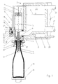
- 1 is a filling element which, together with further, similar filling elements 1, is provided on the circumference of a rotor part 3 which rotates around a vertical machine axis and forms an annular bowl 2.
- the filling element 1 essentially consists of a housing 4 fastened to the rotor 3, in which a liquid channel 5 is formed. This is connected in its upper region to the ring bowl 2 and forms with its lower region an annular discharge opening 7 for a liquid tube which surrounds a gas pipe 6.
- the liquid valve 8 is also provided, which in the usual way has a valve body 9 which interacts with a valve seat formed in the interior of the liquid channel.
- the valve body 9 is in the illustrated embodiment on the in its axis in the vertical direction and parallel to the machine axis arranged, provided on the underside of the filling element 1 and the housing 4 projecting gas pipe 6.
- Fig. 1 the liquid valve is shown in the closed position.
- a pneumatic actuating device is actuated to release the liquid valve 8.
- This actuating device which acts on the part of the gas pipe 6 extending above the valve body 9, contains, for example, a piston as an actuating element, but preferably a membrane, which is indicated schematically in FIG. 1 at 10 by broken lines.
- a fill-level-determining probe 11 is provided, which is enclosed by the gas tube 6 at a distance, so that there is a gas channel 12 within the gas tube 6, which is ring-shaped around the probe 11 and is open at the lower end of the gas tube 6.
- the gas channel 12 opens into a chamber 13 formed in the housing 4 and closed to the outside.
- a valve housing 14 On the radially outer side of the housing 4 with respect to the machine axis, a valve housing 14 is provided there, which forms a chamber 15 which is closed towards the outside. The latter is permanently connected to the chamber 13 via a line or a channel 16 '. The channel 16 'forms a gas path 16 together with the gas channel 12. Furthermore, the chamber 15 is located via a gas path 17 running partly in the valve housing 14, partly in the housing 4 and partly in the rotor part 3, with a gas path 17 provided in the rotor part 3 and common to all filling elements 1 Return gas channel 18 in constant communication.
- a throttle or nozzle 19 is provided in the part of the gas path 17 formed in the valve housing 14. Parallel to the nozzle 19, the gas path 17 forms a bypass in which a check valve 20 is arranged.
- This check valve 20, which in the embodiment shown consists of a ball forming the valve body and a spring, is designed such that it opens in a flow direction out of the gas path 17 into the chamber 15 and prevents a flow in
- the chamber 15 is also connected via a third gas path 21, which is formed by a line or a channel, to a gas space 22 which is in the ring vessel 2, which is not completely filled with the liquid filling material, but only up to a predetermined level N above the filling material level is formed.
- the connection between the gas path 21 and the chamber 15 is controlled by a control valve 23 which, in the non-actuated state shown in FIG. 1, closes the gas path 21 at the junction with the chamber 15 with its valve body 24.
- the control valve 23 can be actuated pneumatically and has a pneumatic actuation device 25.
- FIG. 1 also shows various lines, specifically a line 26 leading into the gas space 22, via which compressed gas is supplied to this gas space in a controlled manner, in such a way that a predetermined pressure is maintained in the gas space 22.
- the liquid filling material is fed to the ring bowl 2 via the line 27, specifically controlled in such a way that a desired level N of the filling material level is maintained (within a predetermined fluctuation range).
- the gas pipe has an opening 6 ′ for the gas channel 12 above its lower end, the cross section of which is smaller than the cross section of the gas channel 12.
- the peculiarity of the filler element 1 described above is that only a single, very simple valve, namely the control valve 23, is sufficient to control the gas paths, which only has two operating states, namely an open state and a closed state. In the embodiment shown, only the control valve 23 and the liquid valve 8 have to be actuated to fill the bottle.
- the control valve 23 is opened by the actuating device 25, so that compressed gas, which in the embodiment shown is sterile air, into the gas path 21, which is now connected to the chamber 15 Chamber 15 and via the gas path 16 and the gas channel 12 into the interior of the bottle 32.
- compressed gas which in the embodiment shown is sterile air
- the bottle 32 is thus biased to a pressure corresponding to the pressure in the gas space 22 via the gas pipe 6 protruding into the interior through the bottle mouth.
- a small amount of pressurized gas also reaches the residual gas duct 18 via the gas path 17. However, by selecting the nozzle 19 accordingly, it is ensured that this amount of pressurized gas is small.
- the control valve 23 is closed again and the liquid valve 8 is opened so that the liquid filling material flows into the interior of the bottle 32 via the discharge opening 7. That out here Compressed or return gas displaced from the interior of the bottle 32 flows via the gas channel 12 and the gas paths 16 and 17 into the return gas chamber 18.
- the nozzle 19 provides for a corresponding throttling of the displaced gas flow and thus for a gentle and slow filling speed.
- the filling speed actually achieved results from the cross section of the nozzle 19 and the difference between the pressure in the gas space 22 and in the residual gas duct 18. Both parameters can be changed or set depending on the sensitivity of the filling material (beverage) to be filled.
- the time for this slow filling is usually only a few 100 milliseconds.
- the bottle 32 is filled after its slow filling in its less critical middle area with a high inflow rate.
- the control valve 23 is opened so that there is then an additional connection to the gas space 22 via the gas path 21, via which an additional, unthrottled gas flow of the gas displaced during filling can be discharged.
- the filling speed in this rapid filling phase is essentially determined by the level N in the ring bowl. Via the level control, the level of level N, i.e. these parameters can be adapted to the respective special requirements (e.g. filling properties of the filling material and / or shape of the bottle 32 to be filled, etc.).
- the control valve 23 is closed again via the actuating device 25, and thus the connection via the gas path 21 to the gas space 22 is interrupted.
- the filling speed is thereby reduced to the value of the filling phase.
- the level of the filling material now rises at a low speed. Small bubbles that go through during the quick fill phase Flow turbulences that were held in suspension rise to the surface.
- the product level reaches the probe 11 arranged in the gas pipe 6 with a uniform surface appearance and free of bubbles.
- the product level which is at a standstill in the braking phase, enables the level to be measured precisely.
- the liquid valve 8 is closed, preferably for a correction filling with a time delay generated, for example, by a control electronics, with which a filling level correction in the range of approximately 10-20 mm is then possible.
- control valve 23 is briefly opened once or several times, so that the filling pressure which corresponds to the pressure in the gas space 22 is maintained in the bottle 32.
- the pressure in the neck of the filled bottle 32 begins to decrease via the nozzle 19 provided in the gas path 17 to the pressure which is set in the residual gas channel 18.
- this relief process or the pre-relief pressure can be adapted to the properties of the respective filling material.
- the corresponding relief cycles, In other words, the opening times can be variably preselected as a time function via the control electronics, regardless of the filler speed.
- the pressure inside the bottle 32 builds up via the nozzle 19 to the pressure prevailing in the residual gas channel 18, which is, for example, between 0.5 and 1.0 bar.
- the pressure regulated in the residual gas channel 18 is maintained in the bottle interior until the bottle 32 is pulled off.
- the bottle 32 is then finally pulled off with a slight excess pressure in the interior of the bottle, with no spraying losses. Since the gas pipe 6 has an opening 6 ', through which the gas channel 12 is connected to the interior of the bottle 32 in the area of the bottle mouth, there is no expansion shock from the gas pipe 6 which disturbs the liquid filling material when the bottle is pulled off.
- An additional relief valve can be used to avoid pulling off with a slight overpressure.
- CIP cleaning is also possible with the filling element 1, as shown in FIG. 2.
- a cap 32 is provided on the underside of the filling element 1, which forms a flushing space which receives the gas pipe 6 and which is sealed off from the outside by a seal 35 of the cap 34, by the centering tulip 30 and its seal 33.
- the cleaning medium used for CIP cleaning is supplied to the residual gas channel 18 with an overpressure, for example with an overpressure of 3.0 to 4.0 bar.
- an overpressure for example with an overpressure of 3.0 to 4.0 bar.
- the cleaning medium enters the chamber 15 and from there flows through the gas path 16 with the return gas channel 12.
- the cleaning medium emerging from the gas pipe 6 into the cap 34 passes through the opened liquid valve 8 in the ring bowl 2, which forms the return of the cleaning medium.
- the cleaning is carried out in such a way that the cleaning medium initially has a pressure which is not yet sufficient to open the check valve 20, and that this pressure then increases to the pressure required to open the check valve. This ensures that the nozzle 19 is rinsed or cleaned sufficiently in any case. If the control valve 23 is open, the cleaning medium also flows through the gas path 21.
- the residual gas channel 18 it is possible for the residual gas channel 18 to communicate with the atmosphere via an opening or nozzle or for the gas path 17 to lead directly to the atmosphere via such an opening or nozzle.
Abstract
Description
Die Erfindung bezieht sich auf eine Vorrichtung zum Füllen von Flaschen oder dergl. Behältern. Eine Vorrichtung dieser Art ist bekannt (DE-PS 16 32 004).The invention relates to a device for filling bottles or the like. Containers. A device of this type is known (DE-PS 16 32 004).
Bei der bekannten Vorrichtung, die ein füllrohrloses Füllelement verwendet, ist der erste Gasweg einerseits mit einem Gasraum verbunden, der über dem Füllgutspiegel im Inneren eines nicht vollständig mit dem flüssigen Füllgut gefüllten Ringkessels einer Füllmaschine gebildet ist und andererseits über das Steuerventil gesteuert mit einem in den Innenraum der zu füllenden Flasche führenden ersten Gaskanal verbunden. Letzterer ist in einem Gasrohr oder rohrartigen Schaft ausgebildet, der den Ventilkörper des Flüssigkeitsventils trägt. Über den Gasweg und den vorerwähnten Gaskanal erfolgt im bekannten Fall das Vorspannen des zu füllenden Behälters.In the known device, which uses a filling element without a filling tube, the first gas path is connected on the one hand to a gas space which is formed above the filling level in the interior of an annular bowl of a filling machine which is not completely filled with the liquid filling content and on the other hand is controlled by a control valve via the control valve Interior of the first gas channel leading to be filled bottle connected. The latter is formed in a gas pipe or tubular shaft which carries the valve body of the liquid valve. In the known case, the container to be filled is pretensioned via the gas path and the aforementioned gas channel.
Bei der bekannten Vorrichtung ist weiterhin ein zweiter Gasweg vorgesehen, der in eine für sämtliche Füllelemente der Füllmaschine gemeinsame Rückgas- oder Restgaskammer führt, die über eine Düse oder Drossel mit der Atmosphäre in Verbindung steht. Weiterhin ist dieser zweite Gasweg ständig mit einem zweiten Gaskanal verbunden, der ebenfalls in dem rohrartigen Schaft des Ventilkörpers ausgebildet und an der über den Ventilkörper vorstehenden unteren Ende dieses Schaftes offen ist. Der zweite Gaskanal umschließt eine im Schaft vorgesehene füllhöhen-bestimmende Sonde.In the known device, a second gas path is also provided, which leads into a return gas or residual gas chamber which is common to all filling elements of the filling machine and which is connected to the atmosphere via a nozzle or throttle. Furthermore, this second gas path is permanently connected to a second gas channel, which is also formed in the tubular shaft of the valve body and is open at the lower end of this shaft projecting above the valve body. The second gas channel encloses a fill level-determining probe provided in the shaft.
Obwohl bei dieser bekannten Vorrichtung für die Steuerung der Gaswege nur ein einziges Steuerventil vorgesehen ist, besitzt diese Vorrichtung gewisse Nachteile. So weist sie zusätzlich zur Notwendigkeit zweier getrennter Gaskanäle in dem Schaft des Ventilkörpers auch sonst eine relativ aufwendige Konstruktion auf. Nachteilig ist ferner, daß für das Steuerventil und das Flüssigkeitsventil eine gemeinsame Betätigungseinrichtung vorgesehen ist, wodurch die Möglichkeit unterschiedlicher Steuerungen bzw. Steuerverfahren stark eingeschränkt ist. Weiterhin sind die Funktionselemente des Steuerventils und dabei insbes. auch der Ventilkörper dieses Steuerventils nur schwer zugänglich.Although only a single control valve is provided in this known device for controlling the gas paths, this device has certain disadvantages. Thus, in addition to the need for two separate gas channels in the stem of the valve body, it also has a relatively complex construction. A further disadvantage is that a common actuating device is provided for the control valve and the liquid valve, which greatly increases the possibility of different controls or control methods is restricted. Furthermore, the functional elements of the control valve and especially the valve body of this control valve are difficult to access.
Der Erfindung liegt die Aufgabe zugrunde, eine Vorrichtung der vorstehenden Art dahingehend weiterzubilden, daß sie unter Beibehaltung der grundsätzlichen Vorteile der bekannten Vorrichtung deren Nachteile vermeidet, insbes. auch bei vereinfachter Konstruktion verbesserte Steuermöglichkeiten schafft.The invention has for its object to develop a device of the above type in such a way that it avoids the disadvantages while maintaining the basic advantages of the known device, in particular. It also provides improved control options with a simplified construction.
Zur Lösung dieser Aufgabe ist eine Vorrichtung entsprechend dem kennzeichnenden Teil des Patentanspruches 1 ausgebildet.To solve this problem, a device is designed according to the characterizing part of patent claim 1.
Bei der erfindungsgemäßen Vorrichtung wird ebenfalls zur Steuerung der Gaswege im einfachsten Fall nur ein einziges Steuerventil benötigt, welches lediglich zwei Zustände besitzt, nämlich einen sperrenden und einen geöffneten Zustand. Mit diesem Steuerventil sind die Gaswege bzw. das Zuführen und Abführen des Druckgases in bzw. aus dem Behälter zumindest für das Vorspannen, für das Gegendruckfüllen (bevorzugt einschließlich langsames Anfüllen, Schnellfüllen und/oder Brems- und Korrekturfüllen) sowie für das Entlasten (bevorzugt einschließlich Beruhigungsphase und/oder Vorentlastungsphase) vollständig steuerbar.In the device according to the invention, in the simplest case, only a single control valve is required to control the gas paths, which only has two states, namely a blocking and an open state. With this control valve, the gas paths or the supply and discharge of the compressed gas into or out of the container are at least for the pretensioning, for the counter pressure filling (preferably including slow filling, quick filling and / or braking and correction filling) as well as for relieving (preferably including Calming phase and / or pre-relief phase) fully controllable.
Da die Betätigungseinrichtung des Steuerventils getrennt ist von der Betätigungseinrichtung des Flüssigkeitsventils und somit das Steuerventil unabhängig von dem Flüssigkeitsventil betätigt werden kann, werden mit der Erfindung Einschränkungen hinsichtlich der Steuermöglichkeiten vermieden.Since the actuating device of the control valve is separate from the actuating device of the liquid valve and thus the control valve can be actuated independently of the liquid valve, restrictions with regard to the control options are avoided with the invention.
Durch die Verwendung eines dritten gemeinsamen Gasweges für die Verbindung des ersten und zweiten Gasweges mit dem jeweiligen Behälter, d. h. sowohl zum Zuführen, als auch zum Abführen des Spanngases in den bzw. aus dem Behälter ergibt sich eine vereinfachte Konstruktion.The use of a third common gas path for connecting the first and second gas paths to the respective container, ie both for supplying and for discharging the tensioning gas into and out of the container, results in a simplified construction.
Weiterhin läßt sich die erfindungsgemäße Vorrichtung so ausbilden, daß das Steuerventil mit allen seinen Funktionselementen ohne Schwierigkeiten von außen her zugänglich bleibt, also auch im Reparaturfalle leicht ausgetauscht werden kann.Furthermore, the device according to the invention can be designed such that the control valve with all its functional elements remains accessible from the outside without difficulty, that is to say can also be easily replaced in the event of a repair.
Weiterbildungen der Erfindung sind Gegenstand der Unteransprüche.Developments of the invention are the subject of the dependent claims.
Die Erfindung wird im Folgenden anhand der Figuren näher erläutert. Es zeigen:
- Fig. 1
- in vereinfachter Darstellung und im Schnitt eines der am Umfang eines um eine vertikale Drehachse umlaufenden Rotors vorgesehenen Füllelemente einer Gegendruckfüllmaschine umlaufender Bauart, zusammen mit einer zu füllenden Flasche;
- Fig. 2
- eine ähnliche Darstellung wie Fig. 1, jedoch bei einer CIP-Reinigung.
- Fig. 1
- in a simplified representation and in section of one of the filling elements of a counterpressure filling machine of the type provided on the circumference of a rotor rotating around a vertical axis of rotation, together with a bottle to be filled;
- Fig. 2
- a representation similar to Fig. 1, but with a CIP cleaning.
In den Figuren ist 1 ein Füllelement, welches zusammen mit weiteren, gleichartigen Füllelementen 1 am Umfang eines um eine vertikale Maschinenachse umlaufenden und einen Ringkessel 2 bildenden Rotorteil 3 vorgesehen ist.In the figures, 1 is a filling element which, together with further, similar filling elements 1, is provided on the circumference of a
Das Füllelement 1 besteht im wesentlichen aus einem am Rotor 3 befestigten Gehäuse 4, in welchem ein Flüssigkeitskanal 5 ausgebildet ist. Dieser steht in seinem oberen Bereich mit dem Ringkessel 2 in Verbindung und bildet mit seinem unteren Bereich eine ein Gasrohr 6 umschließende ringförmige Abgabeöffnung 7 für das flüssige Füllgut.The filling element 1 essentially consists of a housing 4 fastened to the
Im Flüssigkeitskanal 5 ist weiterhin das Flüssigkeitsventil 8 vorgesehen, welches in üblicher Weise einen Ventilkörper 9 aufweist, der mit einem im Inneren des Flüssigkeitskanales gebildeten Ventilsitz zusammenwirkt. Der Ventilkörper 9 ist bei der dargestellten Ausführungsform auf dem in seiner Achse in vertikaler Richtung und parallel zur Maschinenachse angeordneten, über die Unterseite des Füllelementes 1 sowie des Gehäuses 4 vorstehenden Gasrohres 6 vorgesehen. In der Fig. 1 ist das Flüssigkeitsventil in der geschlossenen Stellung dargestellt. Zur Freigabe des Flüssigkeitsventils 8 wird eine pneumatische Betätigungseinrichtung betätigt. Diese Betätigungseinrichtung, die auf den oberhalb des Ventilkörpers 9 sich erstreckenden Teil des Gasrohres 6 einwirkt, enthält als Betätigungselement beispielsweise einen Kolben, bevorzugt aber eine Membrane, die in der Fig. 1 bei 10 mit unterbrochenen Linien schematisch angedeutet ist.In the
Im Gasrohr 6 ist eine füllhöhen-bestimmende Sonde 11 vorgesehen, die vom Gasrohr 6 mit Abstand umschlossen wird, so daß sich innerhalb des Gasrohres 6 ein Gaskanal 12 ergibt, der um die Sonde 11 ringförmig ausgebildet und am unteren Ende des Gasrohres 6 offen ist. Am oberen Ende des Gasrohres 6 mündet der Gaskanal 12 in eine im Gehäuse 4 ausgebildete, nach außen hin geschlossene Kammer 13.In the
An der bezogen auf die Maschinenachse radial außenliegenden Seite des Gehäuses 4 ist an diesem ein Ventilgehäuse 14 vorgesehen, welches eine nach außen hin geschlossene Kammer 15 bildet. Letztere ist über eine Leitung oder einen Kanal 16' ständig mit der Kammer 13 verbunden. Der Kanal 16' bildet zusammen mit dem Gaskanal 12 einen Gasweg 16. Weiterhin steht die Kammer 15 über einen teilweise im Ventilgehäuse 14, teilweise im Gehäuse 4 und teilweise im Rotorteil 3 verlaufenden Gasweg 17 mit einem im Rotorteil 3 vorgesehenen und für sämtliche Füllelemente 1 gemeinsamen Rückgaskanal 18 ständig in Verbindung. In dem im Ventilgehäuse 14 ausgebildeten Teil des Gasweges 17 ist eine Drossel bzw. Düse 19 vorgesehen. Parallel zur Düse 19 bildet der Gasweg 17 einen Bypaß, in welchem ein Rückschlagventil 20 angeordnet ist. Dieses Rückschlagventil 20, welches bei der dargestellten Ausführungsform aus einer den Ventilkörper bildenden Kugel und einer Feder besteht, ist so ausgebildet, daß es in einer Strömungsrichtung aus dem Gasweg 17 heraus in die Kammer 15 öffnet und eine Strömung in umgekehrter Richtung verhindert.On the radially outer side of the housing 4 with respect to the machine axis, a valve housing 14 is provided there, which forms a
Die Kammer 15 steht weiterhin über einen dritten, von einer Leitung oder von einem Kanal gebildeten Gasweg 21 mit einem Gasraum 22 in Verbindung, der in dem nicht vollständig, sondern nur bis zu einem vorgegebenen Niveau N mit dem flüssigen Füllgut gefüllten Ringkessel 2 oberhalb des Füllgutspiegels gebildet ist. Die Verbindung zwischen dem Gasweg 21 und der Kammer 15 ist durch ein Steuerventil 23 gesteuert, welches in dem in der Fig. 1 dargestellten, nicht betätigten Zustand mit seinem Ventilkörper 24 den Gasweg 21 an der Einmündung in die Kammer 15 verschließt. Das Steuerventil 23 ist pneumatisch betätigbar und besitzt eine pneumatische Betätigungseinrichtung 25.The
In der Fig. 1 sind weiterhin noch verschiedene Leitungen dargestellt, und zwar eine in den Gasraum 22 führende Leitung 26, über welche diesem Gasraum gesteuert Druckgas zugeführt wird, und zwar derart, daß in dem Gasraum 22 ein vorgegebener Druck aufrechterhalten wird.1 also shows various lines, specifically a
Über die Leitung 27 wird das flüssige Füllgut dem Ringkessel 2 zugeführt, und zwar derart gesteuert, daß ein gewünschtes Niveau N des Füllgutspiegels (innerhalb einer vorgegebenen Schwankungsbreite) beibehalten wird. Die Leitung 28, die in den Restgaskanal 18 mündet, führt bei der dargestellten Ausführungsform über eine Druckregeleinrichtung zur Atmosphäre, so daß in diesem Kanal ein vorgegebener Druck, der beispielsweise zwischen 0,5 bis 1 bar liegt, aufrechterhalten bleibt.The liquid filling material is fed to the
Mit 30 ist die übliche Zentrierglocke, mit 31 ein heb- und senkbarer Flaschenträger und mit 32 eine auf diesem Flaschenträger bestehende Flasche bezeichnet, die zum Füllen in üblicher Weise gegen das Füllelement 1 angepreßt ist und mit ihrer Mündung unter Mitwirkung einer Dichtung 33 in Dichtlage gegen das Füllelement 1 anliegt. Das Gasrohr besitzt oberhalb seines unteren Endes eine Öffnung 6' für den Gaskanal 12, deren Querschnitt kleiner ist als der Querschnitt des Gaskanales 12.With 30 the usual centering bell, with 31 a liftable and lowerable bottle carrier and with 32 an existing bottle carrier on this bottle, which is pressed for filling in the usual way against the filling element 1 and with its mouth with the help of a
Die Besonderheit des vorstehend beschriebenen Füllelementes 1 besteht darin, daß zur Steuerung der Gaswege lediglich ein einziges, sehr einfach aufgebautes Ventil, nämlich das Steuerventil 23 ausreichend ist, welches lediglich zwei Betriebszustände aufweist, nämlich einen geöffneten Zustand und einen geschlossenen Zustand. Bei der dargestellten Ausführungsform müssen zum Füllen der Flasche also lediglich das Steuerventil 23 und das Flüssigkeitsventil 8 betätigt werden.The peculiarity of the filler element 1 described above is that only a single, very simple valve, namely the
Mit dem Füllelement 1 ist beispielsweise beim Füllen der Flaschen 32 folgender Verfahrensablauf möglich, wobei in der nachfolgenden Beschreibung das Flüssigkeitsventil 8 sowie das Steuerventil 23 sich jeweils in der geschlossenen Stellung befinden, wenn nicht ausdrücklich die geöffnete Stellung dieser Ventile angegeben ist.With the filling element 1, for example, the following process sequence is possible when filling the
Nach dem Anpressen und Abdichten der Flaschenmündung der jeweils zu füllenden Flasche 32 wird das Steuerventil 23 durch die Betätigungseinrichtung 25 geöffnet, so daß über den nunmehr mit der Kammer 15 in Verbindung stehenden Gasweg 21 Druckgas, welches bei der dargestellten Ausführungsform sterile Luft ist, in die Kammer 15 und über den Gasweg 16 und den Gaskanal 12 in das Innere der Flasche 32 gelangt. Die Flasche 32 wird somit über das durch die Flaschenmündung in das Innere vorstehende Gasrohr 6 auf einen Druck vorgespannt, der dem Druck im Gasraum 22 entspricht. Eine geringe Menge an Druckgas gelangt hierbei über den Gasweg 17 auch in den Restgaskanal 18. Durch entsprechende Wahl der Düse 19 ist aber dafür gesorgt, daß diese Menge an Druckgas gering ist.After pressing and sealing the bottle mouth of the
Nach Ablauf einer vorgegebenen Vorspannzeit wird das Steuerventil 23 wieder geschlossen und das Flüssigkeitsventil 8 wird geöffnet, so daß das flüssige Füllgut dem Innenraum der Flasche 32 über die Abgabeöffnung 7 zufließt. Das hierbei aus dem Innenraum der Flasche 32 verdrängte Druck- oder Rückgas fließt über den Gaskanal 12 und die Gaswege 16 und 17 in die Rückgaskammer 18. Die Düse 19 sorgt für eine entsprechende Drosselung des verdrängten Gasstromes und somit für eine schonende und langsame Anfüllgeschwindigkeit. Die tatsächlich erreichte Füllgeschwindigkeit ergibt sich aus dem Querschnitt der Düse 19 und der Differenz zwischen dem Druck im Gasraum 22 und im Restgaskanal 18. Beide Parameter sind in Abhängigkeit von der Empfindlichkeit des abzufüllenden Füllgutes (Getränkes) veränderbar bzw. einstellbar. Die Zeitdauer für dieses langsame Anfüllen beträgt in der Regel nur wenige 100 Millisekunden.After a predetermined pretension time has elapsed, the
Um eine hohe spezifische Ventilleistung zu erreichen, wird die Flasche 32 nach dem langsamen Anfüllen in ihrem unkritischeren Mittelbereich mit hoher Einfließgeschwindigkeit gefüllt. Hierzu wird das Steuerventil 23 geöffnet, so daß dann über den Gasweg 21 eine zusätzliche Verbindung zum Gasraum 22 besteht, über die ein zusätzlicher, ungedrosselter Gasstrom des beim Füllen verdrängten Gases abgeführt werden kann. Die Füllgeschwindigkeit in dieser Schnellfüllphase wird im wesentlichen durch die Höhe des Niveaus N im Ringkessel bestimmt. Über die Niveauregelung kann die Höhe des Niveaus N, d.h. dieser Parameter den jeweiligen speziellen Erfordernissen (z.B. Fülleigenschaften des Füllgutes und/oder Form der zu füllenden Flasche 32 usw.) angepaßt werden.In order to achieve a high specific valve performance, the
Nach Ablauf einer vorgegebenen Zeit für die Schnellfüllphase wird über die Betätigungseinrichtung 25 das Steuerventil 23 wieder geschlossen, und damit die Verbindung über den Gasweg 21 zum Gasraum 22 unterbrochen. Die Füllgeschwindigkeit wird dadurch auf den Wert der Anfüllphase zurückgeführt. In dem sich verengenden Flaschenhals der Flasche 32 steigt jetzt der Spiegel des Füllgutes mit niedriger Geschwindigkeit an. Kleine Blasen, die während der Schnellfüllphase durch Strömungsturbulenzen in der Schwebe gehalten wurden, steigen an die Oberfläche auf. Der Füllgutspiegel erreicht mit gleichmäßigem Oberflächenbild und blasenfrei die im Gasrohr 6 angeordnete Sonde 11. Der in der Bremsphase ruhig gestellte Füllgutspiegel ermöglicht eine präzise Erfassung der Füllhöhe.After a predetermined time for the rapid filling phase, the
Nach dem Belegen der Sonde wird das Flüssigkeitsventil 8 geschlossen, und zwar bevorzugt für eine Korrekturfüllung mit einer von einer Steuerelektronik erzeugten, beispielsweise vorgewählten Zeitverzögerung, mit der dann eine Füllhöhenkorrektur im Bereich von etwa 10 - 20 mm möglich ist.After the probe has been loaded, the
Während dieser Brems- und Korrekturphase wird das Steuerventil 23 gesteuert ein- oder mehrmals kurzzeitig geöffnet, so daß in der Flasche 32 der Fülldruck erhalten bleibt, der dem Druck im Gasraum 22 entspricht.During this braking and correction phase, the
Nach dem Schließen des Flüssigkeitsventils 8 beginnt sich der Druck im Hals der gefüllten Flasche 32 über die im Gasweg 17 vorgesehene Düse 19 auf den Druck abzubauen, der im Restgaskanal 18 eingestellt ist.After the
Auch während dieser Beruhigungsphase ist es möglich, das Steuerventil 23 gesteuert ein- oder mehrmals kurzzeitig zu öffnen, so daß für eine bestimmte Beruhigungszeit im Flascheninneren ein Druck erhalten bleibt, der dem Druck im Gasraum 22 angenähert ist.Even during this calming phase, it is possible to open the
Durch ein- oder mehrmaliges Öffnen und Schließen des Steuerventiles 23 können dieser Entlastungsvorgang bzw. der Vorentlastungsdruck an die Eigenschaften des jeweiligen Füllgutes angepaßt werden. Die entsprechenden Entlastungszyklen, d.h. die Öffnungszeiten sind dabei unabhängig von der Füllerdrehzahl als Zeitfunktion über die Steuerelektronik variabel vorwählbar.By opening or closing the
Nachdem das Steuerventil 23 entgültig geschlossen ist, baut sich der Druck im Inneren der Flasche 32 über die Düse 19 auf den im Restgaskanal 18 herrschenden Druck ab, der beispielsweise zwischen 0,5 und 1,0 bar liegt.After the
Bis zum Abziehen der Flasche 32 wird im Flascheninneren der im Restgaskanal 18 eingeregelte Druck aufrechterhalten. Die Flasche 32 wird dann schließlich bei leichtem Überdruck im Flascheninnenraum abgezogen, wobei Abspritzverluste nicht auftreten. Da das Gasrohr 6 eine Öffnung 6' aufweist, über die der Gaskanal 12 mit dem Innenraum der Flasche 32 im Bereich der Flaschenmündung in Verbindung steht, entsteht beim Abziehen der Flasche kein das flüssige Füllgut beunruhigender Expansionsstoß aus dem Gasrohr 6 heraus. Das Abziehen bei leichtem Überdruck kann durch ein zusätzliches Entlastungsventil vermieden werden.The pressure regulated in the
Beim Abziehen der Flasche 32 strömt aus dem Restgaskanal 18 über die Düse 19 und das Gasrohr 6 ein stark reduzierter Gasstrom in die Mündung der Flasche 32. Dieser Gasstrom streift evtl. am Gasrohr 6 haftende Füllgutreste in die Flasche 32 ab. Weiterhin wird durch diesen Gasstrom auch ein Eindringen von Umgebungsluft in die Mündung der Flasche 32 verhindert. Falls dieser Gasstrom nicht erwünscht ist, kann ein weiteres, den Gasweg 17 steuerndes Steuerventil vorgesehen sein.When the
Modifikationen des vorbeschriebenen Verfahrensablaufes sind selbstverständlich möglich. So ist es beispielsweise möglich, als Druckgas ein Inert-Gas (CO₂) oder ein Luft-Gas-Gemisch mit einem hohen Inert-Gas-Anteil (CO₂-Anteil) zu verwenden.Modifications to the process sequence described above are of course possible. For example, it is possible to use an inert gas (CO₂) or an air-gas mixture with a high proportion of inert gas (CO₂) as the compressed gas.
Weiterhin ist es auch möglich, die jeweilige Flasche 32 vor dem Vorspannen mit dem verwendeten Druckgas zu spülen, und zwar durch Öffnen des Steuerventiles 23, wobei die Flasche 32 nur soweit angehoben ist, daß das Gasrohr 6 in den Innenraum der Flasche reicht, aber an der Mündung der Flasche 32 zwischen dieser und dem Füllelement 1 ein Spalt verbleibt.Furthermore, it is also possible to flush the
Bei dem Füllelement 1 ist weiterhin auch eine CIP-Reinigung möglich, wie dies in der Fig. 2 dargestellt. Für diese Reinigung wird an der Unterseite des Füllelementes 1 eine Kappe 32 vorgesehen, die einen das Gasrohr 6 aufnehmenden Spülraum bildet, der durch eine Dichtung 35 der Kappe 34, durch die Zentriertulpe 30 und deren Dichtung 33 nach außen hin dicht abgeschlossen ist.CIP cleaning is also possible with the filling element 1, as shown in FIG. 2. For this cleaning, a
Das für die CIP-Reinigung verwendete Reinigungsmedium wird mit einem Überdruck, beispielsweise mit einem Überdruck von 3,0 bis 4,0 bar dem Restgaskanal 18 zugeführt. Zunächst über die Düse 19 und dann auch über das sich öffnende Rückschlagventil 20 gelangt das Reinigungsmedium in die Kammer 15 und durchströmt von dort den Gasweg 16 mit dem Rückgaskanal 12. Das an dem Gasrohr 6 in die Kappe 34 austretende Reinigungsmedium gelangt über das geöffnete Flüssigkeitsventil 8 in den Ringkessel 2, der den Rücklauf des Reinigungsmediums bildet. Die Reinigung erfolgt hierbei speziell so, daß das Reinigungsmedium zunächst einen Druck aufweist, der für ein Öffnen des Rückschlagventiles 20 noch nicht ausreicht, und daß sich dieser Druck dann auf den zum Öffnen des Rückschlagventiles notwendigen Druck erhöht. Hierdurch wird sichergestellt, daß zunächst auf jeden Fall die Düse 19 ausreichend gespült bzw. gereinigt wird. Ist das Steuerventil 23 geöffnet, so durchströmt das Reinigungsmedium auch den Gasweg 21.The cleaning medium used for CIP cleaning is supplied to the
Abweichend von der beschriebenen Ausführungsform ist es möglich, daß der Restgaskanal 18 über eine Öffnung oder Düse mit der Atmosphäre in Verbindung steht oder der Gasweg 17 über eine solche Öffnung oder Düse direkt zur Atmosphäre führt.Deviating from the described embodiment, it is possible for the
Claims (13)
- Device for the filling of bottles or the like containers with a liquid filling stock, with at least one filling element (1) displaying a liquid valve (8), with gas paths (16, 17, 21), which are each at least partially formed in the respective filling element (1) and stand in connection with the interior space of the container (32) each by way of a respective connection during the filling and of which a first gas path (21) is connected to a space (22), which holds a pressurising gas at a first pressure, of a tank (2) for the filling stock and a second gas path (17) serves for the discharge of the pressurising gas to a region of a second pressure lying below the first pressure as well as with a control valve (23), which is controllable between an opened and a closed setting and by way of which the first gas path (21) or its connection to the connection leading to the interior space of the container (32) is controllable, whilst the second gas path (17) is constantly connected with the connection leading to the interior space of the container (32), characterised thereby, that a common connection is provided for the first and the second gas path (21, 17) and formed by a third gas path (16), which serves for the feeding as well as also for the discharging of the pressurising gas into or out of the container (32) and that separate actuating equipments (25, 10) are provided for the control valve (23) and the liquid valve (8).
- Device according to claim 1, characterised thereby, that the second and the third gas path (17, 16) are constantly or uncontrollably connected together.
- Device according to claim 1 or 2, characterised thereby, that the control valve (23) is provided at an outward side of the filling element (1) or a housing (4) of this filling element (1) to be easily accessible.
- Device according to one of the claims 1 to 3, characterised thereby, that at least one nozzle or throttle (19) is provided in the second gas path (17) and determines the effective flow cross-section of this gas path.
- Device according to claim 4, characterised thereby, that at least one non-return valve (20) is provided parallelly to the at least one nozzle (19) in the second gas path (17) and opens in a flow direction which extends in the second gas path (17) in the direction to the connection with the third gas path (16) and/or the first gas path (21).
- Device according to one of the preceding claims, characterised thereby, that the gas paths (16, 17, 21) open into a common chamber (15).
- Device accoridng to claim 6, characterised thereby, that a valve body (24) of the control valve (23) is provided in the common chamber (15).
- Device according to one of the claims 1 to 7, characterised thereby, that the first gas path (21) is connected with a pressurising gas chamber or a gas space of a tank (2) filled only partially by the liquid filling stock.
- Device according to one of the claims 1 to 8, characterised thereby, that the second gas path (17) stands in connection with the atmosphere.
- Device according to one of the claims 1 to 8, characterised thereby, that the second gas path (17) stands in connection with a return gas channel or rest gas channel (18).
- Device according to one of the claims 1 to 10, characterised by means for the maintenance of a preset value of the second pressure, preferably for the maintenance of a preset pressure in the return gas channel or rest gas channel (18).
- Device according to one of the claims 1 to 11, characterised thereby, that the third gas path (16) includes a gas channel (12), which is formed in a gas tube (6) of the filling element and preferably surrounds a probe (11) determining the filling height.
- Device according to claim 12, characterised thereby, that the gas tube (6) above its lower end displays an additional opening for the gas channel (12).
Applications Claiming Priority (2)
| Application Number | Priority Date | Filing Date | Title |
|---|---|---|---|
| DE4231114 | 1992-09-17 | ||
| DE4231114A DE4231114A1 (en) | 1992-09-17 | 1992-09-17 | Device for filling bottles or similar containers |
Publications (2)
| Publication Number | Publication Date |
|---|---|
| EP0588356A1 EP0588356A1 (en) | 1994-03-23 |
| EP0588356B1 true EP0588356B1 (en) | 1995-12-06 |
Family
ID=6468179
Family Applications (1)
| Application Number | Title | Priority Date | Filing Date |
|---|---|---|---|
| EP93114985A Expired - Lifetime EP0588356B1 (en) | 1992-09-17 | 1993-09-17 | Filling divice for bottles or like containers |
Country Status (5)
| Country | Link |
|---|---|
| US (1) | US5402833A (en) |
| EP (1) | EP0588356B1 (en) |
| AT (1) | ATE131135T1 (en) |
| DE (2) | DE4231114A1 (en) |
| ES (1) | ES2080569T3 (en) |
Cited By (1)
| Publication number | Priority date | Publication date | Assignee | Title |
|---|---|---|---|---|
| DE102022102540A1 (en) | 2022-02-03 | 2023-08-03 | Khs Gmbh | Filling machine and method for filling containers using a filling machine |
Families Citing this family (14)
| Publication number | Priority date | Publication date | Assignee | Title |
|---|---|---|---|---|
| US6338370B1 (en) | 2000-05-31 | 2002-01-15 | Fogg Filler Company | Fill valve assembly for filler device and associated method |
| US7040075B2 (en) | 2001-08-08 | 2006-05-09 | The Clorox Company | Nitrogen cap chute end |
| US6786248B2 (en) | 2001-10-11 | 2004-09-07 | Fogg Filler Company | Fill valve assembly for filler device |
| US6889482B2 (en) | 2002-10-10 | 2005-05-10 | Fogg Filler Company | Filler device sub-assembly |
| DE102007022259A1 (en) * | 2007-05-09 | 2009-01-15 | Khs Ag | Filling system and method for controlling a filling system |
| US8915270B2 (en) | 2009-10-05 | 2014-12-23 | Fogg Filler Company | Filler device having an enclosure sub-assembly |
| CN101746701B (en) * | 2010-01-14 | 2011-05-11 | 安丘市鼎正机械设备有限公司 | Variable flow rate intelligent sense filling valve |
| DE102010024522A1 (en) * | 2010-06-21 | 2011-12-22 | Khs Gmbh | Method and filling element for pressure filling of containers with a liquid product |
| DE102010027512A1 (en) * | 2010-07-16 | 2012-01-19 | Khs Gmbh | Filling element, method and filling system for filling containers |
| US10597277B2 (en) | 2011-07-08 | 2020-03-24 | Fogg Filler Company | Fill valve assembly for filler device and associated method of use |
| DE102011116469A1 (en) * | 2011-10-20 | 2013-04-25 | Khs Gmbh | Method and filling machine for filling bottles or the like. Containers (2) with a liquid product |
| DE102011120164A1 (en) * | 2011-12-06 | 2013-06-06 | Khs Gmbh | Filling element and filling system |
| DE102014109589A1 (en) * | 2014-07-09 | 2016-01-14 | Khs Gmbh | Filling system for filling bottles or similar containers |
| CN109592623A (en) * | 2019-02-02 | 2019-04-09 | 长沙康欧创新科技有限公司 | A kind of liquid-filling machine |
Family Cites Families (9)
| Publication number | Priority date | Publication date | Assignee | Title |
|---|---|---|---|---|
| DE1607996A1 (en) * | 1967-07-22 | 1972-03-02 | Seitz Werke Gmbh | Filling element for counter pressure filling machine |
| DE1632004C3 (en) * | 1967-12-16 | 1975-11-20 | Seitz-Werke Gmbh, 6550 Bad Kreuznach | Filling element for single or multi-chamber counter pressure filling machines |
| DE2234120C3 (en) * | 1972-07-12 | 1979-08-09 | Seitz-Werke Gmbh, 6550 Bad Kreuznach | Filling element with long downpipe for multi-chamber counter pressure filling machines |
| US4201249A (en) * | 1977-10-11 | 1980-05-06 | Holstein Und Kappert Gmbh | Machine for the filling of liquids into containers |
| DE3024099A1 (en) * | 1980-06-27 | 1982-01-21 | Seitz-Werke Gmbh, 6550 Bad Kreuznach | METHOD AND DEVICE FOR RECOVERY OF AN INERT GAS |
| DE3717256A1 (en) * | 1987-05-22 | 1988-12-01 | Seitz Enzinger Noll Masch | METHOD AND DEVICE FOR FILLING CARBONIC LIQUIDS, IN PARTICULAR DRINKS, UNDER BACK PRESSURE IN VESSEL OD. DGL. |
| DE3807046A1 (en) * | 1988-03-04 | 1989-10-12 | Seitz Enzinger Noll Masch | METHOD AND DEVICE FOR FILLING CARBONIC LIQUIDS, IN PARTICULAR DRINKS, UNDER BACK PRESSURE IN VESSELS OR THE LIKE. |
| DE3809852A1 (en) * | 1988-03-24 | 1989-10-05 | Seitz Enzinger Noll Masch | METHOD FOR ASEPTIC OR STERILE FILLING OF LIQUID FILLING MATERIAL IN CONTAINERS AND DEVICE FOR CARRYING OUT THIS PROCESS |
| DE3825093C2 (en) * | 1988-07-23 | 1994-01-13 | Kronseder Maschf Krones | Method and device for filling bottles or the like in counterpressure filling machines |
-
1992
- 1992-09-17 DE DE4231114A patent/DE4231114A1/en not_active Withdrawn
-
1993
- 1993-09-17 ES ES93114985T patent/ES2080569T3/en not_active Expired - Lifetime
- 1993-09-17 EP EP93114985A patent/EP0588356B1/en not_active Expired - Lifetime
- 1993-09-17 AT AT93114985T patent/ATE131135T1/en not_active IP Right Cessation
- 1993-09-17 DE DE59301094T patent/DE59301094D1/en not_active Expired - Fee Related
- 1993-09-17 US US08/123,005 patent/US5402833A/en not_active Expired - Lifetime
Cited By (1)
| Publication number | Priority date | Publication date | Assignee | Title |
|---|---|---|---|---|
| DE102022102540A1 (en) | 2022-02-03 | 2023-08-03 | Khs Gmbh | Filling machine and method for filling containers using a filling machine |
Also Published As
| Publication number | Publication date |
|---|---|
| EP0588356A1 (en) | 1994-03-23 |
| ES2080569T3 (en) | 1996-02-01 |
| DE4231114A1 (en) | 1994-03-24 |
| US5402833A (en) | 1995-04-04 |
| DE59301094D1 (en) | 1996-01-18 |
| ATE131135T1 (en) | 1995-12-15 |
Similar Documents
| Publication | Publication Date | Title |
|---|---|---|
| EP0697369B1 (en) | Method for filling bottles or the like with a liquid | |
| EP0588356B1 (en) | Filling divice for bottles or like containers | |
| DE10359492B3 (en) | Filling element for a filling machine | |
| EP0582190B1 (en) | Filling device for bottles or similar containers | |
| EP2029469B1 (en) | Filling element and filling machine comprising corresponding filling elements | |
| EP0953542B1 (en) | Filling valve for a filling machine | |
| EP0331137B1 (en) | Method and device for the counter-pressure filling of containers with carbonated liquids, especially with beverages | |
| DE3825093A1 (en) | METHOD AND DEVICE FOR FILLING BOTTLES OR THE LIKE IN COUNTERPRESSURE MACHINES | |
| WO2014183827A1 (en) | Filling system and filling machine for filling containers | |
| WO2005019090A1 (en) | Counter-pressure filling device and method for counter-pressure filling | |
| DE823263C (en) | Control head for devices for filling gaseous or non-gaseous liquids | |
| DE2002060A1 (en) | Filler tube-less filling element for counter pressure filling machines in single or multi-chamber construction | |
| DE4402980C1 (en) | Gravity bottle filling device for still and fizzy beverages | |
| EP0705788B1 (en) | Method for filling bottles or similar containers with a liquid product | |
| DE4342142C2 (en) | Device for filling bottles or similar containers with a liquid filling material | |
| DE2947035C2 (en) | Filling element for counter pressure vessel filling machine | |
| DE4324592C1 (en) | Method and device for pouring liquid into vessels | |
| DE102016105552A1 (en) | Filling valve for filling a container with a filling product | |
| EP2576420B1 (en) | Filling element and filling machine for filling bottles or similar containers | |
| DE4201698A1 (en) | METHOD FOR FILLING BOTTLES OR THE LIKE CONTAINER WITH A LIQUID FILLING MATERIAL AND DEVICE FOR CARRYING OUT THIS METHOD | |
| EP0308723B1 (en) | Filling head for beverage filling equipment | |
| DE4323746A1 (en) | Method and device for influencing the filling quantity when filling liquids into bottles | |
| EP0416473B1 (en) | Filling head for counter pressure bottling machine | |
| WO2007104327A1 (en) | Discharge device for a flowable medium and dispenser device with such a discharge device | |
| EP0379102A1 (en) | Device for the dosed pouring of a liquid or pasty filling material into containers |
Legal Events
| Date | Code | Title | Description |
|---|---|---|---|
| PUAI | Public reference made under article 153(3) epc to a published international application that has entered the european phase |
Free format text: ORIGINAL CODE: 0009012 |
|
| AK | Designated contracting states |
Kind code of ref document: A1 Designated state(s): AT BE DE ES FR GB IT NL |
|
| 17P | Request for examination filed |
Effective date: 19940816 |
|
| 17Q | First examination report despatched |
Effective date: 19950222 |
|
| ITF | It: translation for a ep patent filed |
Owner name: BARZANO' E ZANARDO ROMA S.P.A. |
|
| GRAA | (expected) grant |
Free format text: ORIGINAL CODE: 0009210 |
|
| AK | Designated contracting states |
Kind code of ref document: B1 Designated state(s): AT BE DE ES FR GB IT NL |
|
| REF | Corresponds to: |
Ref document number: 131135 Country of ref document: AT Date of ref document: 19951215 Kind code of ref document: T |
|
| GBT | Gb: translation of ep patent filed (gb section 77(6)(a)/1977) |
Effective date: 19951218 |
|
| REF | Corresponds to: |
Ref document number: 59301094 Country of ref document: DE Date of ref document: 19960118 |
|
| ET | Fr: translation filed | ||
| REG | Reference to a national code |
Ref country code: ES Ref legal event code: FG2A Ref document number: 2080569 Country of ref document: ES Kind code of ref document: T3 |
|
| PG25 | Lapsed in a contracting state [announced via postgrant information from national office to epo] |
Ref country code: AT Effective date: 19960917 |
|
| PG25 | Lapsed in a contracting state [announced via postgrant information from national office to epo] |
Ref country code: ES Free format text: LAPSE BECAUSE OF NON-PAYMENT OF DUE FEES Effective date: 19960918 |
|
| PG25 | Lapsed in a contracting state [announced via postgrant information from national office to epo] |
Ref country code: BE Effective date: 19960930 |
|
| PLBE | No opposition filed within time limit |
Free format text: ORIGINAL CODE: 0009261 |
|
| STAA | Information on the status of an ep patent application or granted ep patent |
Free format text: STATUS: NO OPPOSITION FILED WITHIN TIME LIMIT |
|
| 26N | No opposition filed | ||
| BERE | Be: lapsed |
Owner name: KHS MASCHINEN- UND ANLAGENBAU A.G. Effective date: 19960930 |
|
| PG25 | Lapsed in a contracting state [announced via postgrant information from national office to epo] |
Ref country code: NL Free format text: LAPSE BECAUSE OF NON-PAYMENT OF DUE FEES Effective date: 19980401 |
|
| NLV4 | Nl: lapsed or anulled due to non-payment of the annual fee |
Effective date: 19980401 |
|
| PGFP | Annual fee paid to national office [announced via postgrant information from national office to epo] |
Ref country code: DE Payment date: 20010711 Year of fee payment: 9 |
|
| PGFP | Annual fee paid to national office [announced via postgrant information from national office to epo] |
Ref country code: GB Payment date: 20010914 Year of fee payment: 9 |
|
| PGFP | Annual fee paid to national office [announced via postgrant information from national office to epo] |
Ref country code: FR Payment date: 20010926 Year of fee payment: 9 |
|
| REG | Reference to a national code |
Ref country code: GB Ref legal event code: IF02 |
|
| PG25 | Lapsed in a contracting state [announced via postgrant information from national office to epo] |
Ref country code: GB Free format text: LAPSE BECAUSE OF NON-PAYMENT OF DUE FEES Effective date: 20020917 |
|
| PG25 | Lapsed in a contracting state [announced via postgrant information from national office to epo] |
Ref country code: DE Free format text: LAPSE BECAUSE OF NON-PAYMENT OF DUE FEES Effective date: 20030401 |
|
| GBPC | Gb: european patent ceased through non-payment of renewal fee |
Effective date: 20020917 |
|
| PG25 | Lapsed in a contracting state [announced via postgrant information from national office to epo] |
Ref country code: FR Free format text: LAPSE BECAUSE OF NON-PAYMENT OF DUE FEES Effective date: 20030603 |
|
| REG | Reference to a national code |
Ref country code: FR Ref legal event code: ST |
|
| REG | Reference to a national code |
Ref country code: ES Ref legal event code: FD2A Effective date: 19971011 |
|
| PG25 | Lapsed in a contracting state [announced via postgrant information from national office to epo] |
Ref country code: IT Free format text: LAPSE BECAUSE OF NON-PAYMENT OF DUE FEES;WARNING: LAPSES OF ITALIAN PATENTS WITH EFFECTIVE DATE BEFORE 2007 MAY HAVE OCCURRED AT ANY TIME BEFORE 2007. THE CORRECT EFFECTIVE DATE MAY BE DIFFERENT FROM THE ONE RECORDED. Effective date: 20050917 |