EP0587905B1 - Data recording medium and data recording apparatus - Google Patents
Data recording medium and data recording apparatus Download PDFInfo
- Publication number
- EP0587905B1 EP0587905B1 EP93906839A EP93906839A EP0587905B1 EP 0587905 B1 EP0587905 B1 EP 0587905B1 EP 93906839 A EP93906839 A EP 93906839A EP 93906839 A EP93906839 A EP 93906839A EP 0587905 B1 EP0587905 B1 EP 0587905B1
- Authority
- EP
- European Patent Office
- Prior art keywords
- signal
- data recording
- detector
- recording medium
- signals
- Prior art date
- Legal status (The legal status is an assumption and is not a legal conclusion. Google has not performed a legal analysis and makes no representation as to the accuracy of the status listed.)
- Expired - Lifetime
Links
- 238000004519 manufacturing process Methods 0.000 abstract description 3
- 230000003287 optical effect Effects 0.000 description 10
- 238000010586 diagram Methods 0.000 description 4
- 238000001514 detection method Methods 0.000 description 2
- 230000007246 mechanism Effects 0.000 description 2
- 239000002131 composite material Substances 0.000 description 1
- 238000000034 method Methods 0.000 description 1
- 239000000203 mixture Substances 0.000 description 1
Images


Classifications
-
- G—PHYSICS
- G11—INFORMATION STORAGE
- G11B—INFORMATION STORAGE BASED ON RELATIVE MOVEMENT BETWEEN RECORD CARRIER AND TRANSDUCER
- G11B5/00—Recording by magnetisation or demagnetisation of a record carrier; Reproducing by magnetic means; Record carriers therefor
- G11B5/48—Disposition or mounting of heads or head supports relative to record carriers ; arrangements of heads, e.g. for scanning the record carrier to increase the relative speed
- G11B5/58—Disposition or mounting of heads or head supports relative to record carriers ; arrangements of heads, e.g. for scanning the record carrier to increase the relative speed with provision for moving the head for the purpose of maintaining alignment of the head relative to the record carrier during transducing operation, e.g. to compensate for surface irregularities of the latter or for track following
- G11B5/596—Disposition or mounting of heads or head supports relative to record carriers ; arrangements of heads, e.g. for scanning the record carrier to increase the relative speed with provision for moving the head for the purpose of maintaining alignment of the head relative to the record carrier during transducing operation, e.g. to compensate for surface irregularities of the latter or for track following for track following on disks
- G11B5/59677—Disposition or mounting of heads or head supports relative to record carriers ; arrangements of heads, e.g. for scanning the record carrier to increase the relative speed with provision for moving the head for the purpose of maintaining alignment of the head relative to the record carrier during transducing operation, e.g. to compensate for surface irregularities of the latter or for track following for track following on disks with optical servo tracking
-
- G—PHYSICS
- G11—INFORMATION STORAGE
- G11B—INFORMATION STORAGE BASED ON RELATIVE MOVEMENT BETWEEN RECORD CARRIER AND TRANSDUCER
- G11B21/00—Head arrangements not specific to the method of recording or reproducing
- G11B21/02—Driving or moving of heads
- G11B21/08—Track changing or selecting during transducing operation
- G11B21/081—Access to indexed tracks or parts of continuous track
- G11B21/083—Access to indexed tracks or parts of continuous track on discs
- G11B21/085—Access to indexed tracks or parts of continuous track on discs with track following of accessed part
-
- G—PHYSICS
- G11—INFORMATION STORAGE
- G11B—INFORMATION STORAGE BASED ON RELATIVE MOVEMENT BETWEEN RECORD CARRIER AND TRANSDUCER
- G11B21/00—Head arrangements not specific to the method of recording or reproducing
- G11B21/02—Driving or moving of heads
- G11B21/10—Track finding or aligning by moving the head ; Provisions for maintaining alignment of the head relative to the track during transducing operation, i.e. track following
Definitions
- the present invention relates to a data recording medium and a data recording apparatus for performing tracking by using continuous servo signals, and particularly to a data recording medium and a data recording apparatus suitable for use when an optical means is used to perform tracking.
- a number of floppy disk systems are being used for recording data in computers and word processors.
- a head is positioned under open loop control (control without feedback) using a step motor, there have been problems of poor positioning accuracy and inability to increase track density.
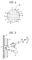
- Figs. 3-4 show an exemplary application of this principle to a floppy disk 19.
- Fig. 4 is an enlarged view of a portion IV of Fig. 3.
- Fig. 5 is a sectional view perpendicular to the surface of a medium showing a servo signal read system in an optical track servo mechanism.
- Light is projected from a light emitting element 8 through a hole 7 in the center of a head 6 onto the surface of the medium 4.
- a light receiving element 10 reads the light reflected from the medium 4 through an optical system 9 to perform tracking.
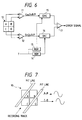
- Figs. 6 and 7 show a tracking error detection circuit and an optical detector.
- Reference character P in the following denotes a track pitch.
- the light receiving element 10 comprises four unit elements arranged in the form of a square grid and outputs four signals A-D on receiving the reflected light.
- a differential amplifier 11 subtracts the signal B from the signal A, whereby a signal proportional to cos(2 ⁇ R/P) is obtained.
- a differential amplifier 12 subtracts the signal D from the signal C, whereby a signal proportional to sin(2 ⁇ R/P) is obtained.
- binary codes indicating sin(2 ⁇ T/P)and cos(2 ⁇ T/P) are formed by supplying a binary code of a target value T to ROMs 13 and 14 with sin and cos tables written thereto.
- the binary codes are then converted to analog signals by multiplication type DA converters 15 and 16, which are multiplied by the signals sin(2 ⁇ R/P)and cos(2 ⁇ R/P) obtained from the optical detector, and subtraction is carried out by a differential amplifier 17, so that an error signal is obtained by carrying out the operations shown by the following equations.
- cos(2 ⁇ T/P)sin(2 ⁇ R/P) - sin(2 ⁇ T/P)cos(2 ⁇ R/P) sin((2 ⁇ R/P) - (2 ⁇ T/P)) ⁇ 2 ⁇ (R - T) / P
- a tracking servomechanism of the sort as stated above necessitates two sets of detectors and therefore the problem is that not only the size but also the manufacturing costs of the apparatus is rendered greater.
- a disk-like data recording medium of the present invention having coaxial tracks on which continuous servo signals to be optically read are recorded is characterized in that the servo signal includes a signal resulting from superimposing two kinds of signals which are different in wavelength and that the two kinds of signals each are uniform with the phase difference therebetween sequentially differing on a track basis.
- the data recording medium of the present invention may be made a magnetic recording medium.
- a system of the present invention comprising a data recording apparatus and a dish-like recording medium is defined in claim 3.
- the data recording apparatus in the system of the present invention may be arranged so that the two kinds of signals different in wavelength are recorded in respective positions different from each other and that a signal resulting from superimposing the two kinds of uniform signals different in wavelength is obtained by reading the two kinds of signals different in wavelength by means of one single detector.
- the present invention is characterized in that a signal resulting from superimposing two uniform signals different in wavelength is used as a servo signal and that the phase difference between the signals sequentially differs on a track basis. Tracking is performed by separating the servo signal thus read out into frequency components corresponding to the two wavelengths and detecting the phase difference between the two frequency components.
- the signal having the two signals different in wavelength and superimposed on each other may be recorded on one servo track, or the signal having the two uniform signals different in wavelength and superimposed on each other may be obtained from one single detector through recording the two signals different in wavelength at positions spatially different from but close to each other.
- any track position is made detectable by measuring the phase difference. Since the two signals are different in frequency, moreover, they may be separated from each other by a filter or the like.
- the detected signal is a composite signal of both and the phase difference between the signals obtained via the separator means such as a filter shows an intermediate value between the signals obtained from the respective tracks. More specifically, the detector outputs the servo signals from two tracks at a ratio corresponding to the track positions. When signals different in phase are mixed, there is shown an intermediate phase corresponding to the mixture ratio. Therefore, the position of a head can be obtained by detecting the phase relationship.
- Fig. 1 is an exemplary diagram of a condition wherein a servo signal pattern on a data recording medium is read by a detector.
- Fig. 2 is a block diagram of a servo signal detector.
- Fig. 3 is a perspective view of a floppy disk.
- Fig. 4 is an exemplary enlarged view of a portion IV of the surface of the disk of Fig. 3.
- Fig. 5 is a sectional view of a servo signal read system in a conventional optical track servomechanism.
- Fig. 6 is a block diagram of a detection circuit in the conventional optical track servomechanism.
- Fig. 7 is a diagram illustrating the relation between a detector and a medium in the conventional optical track servomechanism.
- Fig. 1 shows an exemplary data recording medium embodying the present invention, wherein a long wavelength signal 21 and a short wavelength signal 22 are read by a detector 31.
- a medium like this can be manufactured by effecting laser irradiation at prescribed positions on the surface of a magnetic recording medium such as a floppy disk.
- the signals 21 and 22 are recorded at positions different from but close to each other on the surface of the medium.
- the signals thus closely recorded are mixed together at the time of reproduction and a combination of both is output from the detector.
- a similar output may be obtained by adding trigonometric functions corresponding to the two signals and making the result correspond to the intensity or the width of optical recording or otherwise converting the result by PWM (Pulse Width Modulation) to a binary signal for recording purposes.
- PWM Pulse Width Modulation
- the signal 22 has half the wavelength ( ⁇ ) of the signal 21 and in recorded in such a way that its phase sequentially differs on a track basis with respect to the signal 21.
- the phase phase difference between the signals 21 and 22 is set sequentially different, for example, at 0 on the track 3 as shown by b , ⁇ /8 on the track 2 as shown by a and ⁇ /4 on the track 1 as shown by c .
- phase difference between the signals 21 and 22 is caused to sequentially differ on a track basis by making equal the phases of signals 21 track to track while sequentially changing those of the signals 22 for respective tracks
- sequential change of the phase difference may be accomplished by changing both the phases of the signals 21 and 22 sequentially at a different ratio from each other for each track.
- i refers to a case where the detector 31 is located right above the track 2 and a signal d which the detector 31 outputs in this case corresponds to the signal on the track 2.
- the signal d from the detector is mixed with a signal on the track 3 and the phase of the short wavelength component then advances.
- the detector 31 conversely moves downward and reaches a position iii , the signal d from the detector is mixed with a signal on the track 1 and the phase of the short wavelength component then lags.
- the position of the detector is thus detected as the phase difference. Since the phase difference between the short wavelength components is thus detected, tracking is accurately performed by moving a head so that the detected phase difference is held within a predetermined range.
- the signal that the detector outputs is processed in a circuit shown in Fig. 2.
- the detected signal d from the detector 31 is amplified by an amplifier 32 up to a prescribed level and then the amplified signal is separated into two signals by band-pass filters 33 and 34 for passing only respective wavelength components therethrough.
- a signal indicating a track position is subsequently obtained by measuring the phase difference between both the signals by a phase detector 35.
- a servomechanism for performing tracking by making use of a phase difference.
- a servo circuit generally known as a PLL (Phase Locked Loop) is nothing but a circuit which uses a phase difference as a signal source, and capable of accurately performing tracking by controlling a head position under PLL control so that the phases of the following signals may conform to each other, the signals being obtained by subjecting the short and long wavelength components of the two signals to four and eight times frequency multiplication in a frequency multiplier, respectively.
- a digital signal processor is used to constitute a servomechanism, it is used to read the rise time of the two signals and to compute the difference therebetween. A tracking error is thus simply obtainable.
- the data recording medium and the data recording apparatus according to the present invention are capable of accurately detecting the head position by means of one single detector and this greatly contributes to reducing not only the size but also manufacturing costs of the apparatus; therefore, these are suitable for use as large capacity data recording medium and apparatus.
Landscapes
- Moving Of The Head To Find And Align With The Track (AREA)
- Magnetic Record Carriers (AREA)
Applications Claiming Priority (5)
| Application Number | Priority Date | Filing Date | Title |
|---|---|---|---|
| JP76744/92 | 1992-03-31 | ||
| JP7674492 | 1992-03-31 | ||
| JP334316/92 | 1992-12-15 | ||
| JP33431692A JP3275404B2 (ja) | 1992-03-31 | 1992-12-15 | 情報記録媒体および情報記録装置 |
| PCT/JP1993/000380 WO1993020557A1 (fr) | 1992-03-31 | 1993-03-29 | Suppport d'enregistrement de donnees et appareil d'enregistrement de donnees |
Publications (3)
| Publication Number | Publication Date |
|---|---|
| EP0587905A1 EP0587905A1 (en) | 1994-03-23 |
| EP0587905A4 EP0587905A4 (enExample) | 1994-08-03 |
| EP0587905B1 true EP0587905B1 (en) | 1997-09-03 |
Family
ID=26417879
Family Applications (1)
| Application Number | Title | Priority Date | Filing Date |
|---|---|---|---|
| EP93906839A Expired - Lifetime EP0587905B1 (en) | 1992-03-31 | 1993-03-29 | Data recording medium and data recording apparatus |
Country Status (4)
| Country | Link |
|---|---|
| EP (1) | EP0587905B1 (enExample) |
| JP (1) | JP3275404B2 (enExample) |
| DE (1) | DE69313569T2 (enExample) |
| WO (1) | WO1993020557A1 (enExample) |
Families Citing this family (1)
| Publication number | Priority date | Publication date | Assignee | Title |
|---|---|---|---|---|
| US6055139A (en) | 1995-12-14 | 2000-04-25 | Fujitsu Limited | Magnetic recording medium and method of forming the same and magnetic disk drive |
Family Cites Families (10)
| Publication number | Priority date | Publication date | Assignee | Title |
|---|---|---|---|---|
| US4048660A (en) * | 1975-12-23 | 1977-09-13 | International Business Machines Corporation | Record track following and seeking |
| JPS5873023A (ja) * | 1981-10-27 | 1983-05-02 | Pioneer Electronic Corp | 情報読取装置におけるトラツキングサ−ボ信号発生装置 |
| WO1985002933A1 (en) * | 1983-12-27 | 1985-07-04 | Ncr Corporation | Magnetic record medium and apparatus and method for tracking the same |
| JPS6139239A (ja) * | 1984-07-28 | 1986-02-25 | Sony Corp | 光学式デイスクプレ−ヤ |
| JP2628155B2 (ja) * | 1987-01-13 | 1997-07-09 | キヤノン電子株式会社 | ヘッドトラッキング用サーボパターンを備えた記録媒体 |
| JP2696822B2 (ja) * | 1987-01-22 | 1998-01-14 | ソニー株式会社 | トラツキングサーボ装置 |
| JPH03280275A (ja) * | 1990-03-28 | 1991-12-11 | Toshiba Corp | 磁気記録再生装置 |
| US5121371A (en) * | 1990-06-18 | 1992-06-09 | Bernoulli Optical Systems Company | Optical servo system for magnetic disk |
| JP2608220B2 (ja) * | 1992-01-31 | 1997-05-07 | 富士通株式会社 | 磁気ディスク装置のポジション感度調整方法 |
| ES2835230T3 (es) | 2010-11-19 | 2021-06-22 | Henkel Ag & Co Kgaa | Composiciones adhesivas y uso de las mismas |
-
1992
- 1992-12-15 JP JP33431692A patent/JP3275404B2/ja not_active Expired - Fee Related
-
1993
- 1993-03-29 WO PCT/JP1993/000380 patent/WO1993020557A1/ja not_active Ceased
- 1993-03-29 EP EP93906839A patent/EP0587905B1/en not_active Expired - Lifetime
- 1993-03-29 DE DE69313569T patent/DE69313569T2/de not_active Expired - Fee Related
Also Published As
| Publication number | Publication date |
|---|---|
| JP3275404B2 (ja) | 2002-04-15 |
| EP0587905A1 (en) | 1994-03-23 |
| DE69313569D1 (de) | 1997-10-09 |
| EP0587905A4 (enExample) | 1994-08-03 |
| WO1993020557A1 (fr) | 1993-10-14 |
| DE69313569T2 (de) | 1998-01-08 |
| JPH05334821A (ja) | 1993-12-17 |
Similar Documents
| Publication | Publication Date | Title |
|---|---|---|
| EP0336419B1 (en) | Apparatus and method for optical servo control with media having information storage and servo control regions of different reflectivities | |
| EP0530023B1 (en) | Optical recording and reproducing apparatus for tracking wobbling guide grooves | |
| US4611317A (en) | Optical disk apparatus | |
| CA1190645A (en) | Mobile pre-etched data carrier and an optical tracking device using such a carrier | |
| US4989193A (en) | Optical arrangement and a reading apparatus | |
| US4544838A (en) | Method and apparatus for detecting tracking error | |
| US4870508A (en) | Record carrier body with an optical servo track and optical apparatus for writing and reading information from the carrier | |
| US5065387A (en) | Method and apparatus for generating tracking error signals by means of an optical servo system | |
| JPS6390035A (ja) | 光ディスク駆動装置 | |
| US4872152A (en) | Light spot position control system and method by sampled servo | |
| EP0587905B1 (en) | Data recording medium and data recording apparatus | |
| EP0487206B1 (en) | Apparatus for detecting position of light spot | |
| EP0410639B1 (en) | Optical recording and/or reproducing apparatus | |
| EP0523334B1 (en) | Optical information recording medium and reproducing apparatus for reproducing information from the medium | |
| EP0343952A3 (en) | Focus error detection system for an optical recording/reproducing system | |
| US4977539A (en) | High-speed searching apparatus for CDP | |
| JPH06195904A (ja) | 磁気記録媒体 | |
| WO1986002768A1 (en) | Disc device | |
| JPH06187751A (ja) | 磁気記録媒体 | |
| JPH0757411A (ja) | 光学ヘッドおよびこれを用いた情報記録装置 | |
| GB2137746A (en) | Apparatus for Detecting Deviations of Position from a Reference | |
| JP3365856B2 (ja) | 情報記録・再生ヘッド及び信号処理回路 | |
| JP2737917B2 (ja) | 光デイスク装置 | |
| JPH09265642A (ja) | トラッキングエラー検出回路およびその方法 | |
| JPH0745019A (ja) | 信号処理回路及びこれを用いた情報記録装置 |
Legal Events
| Date | Code | Title | Description |
|---|---|---|---|
| PUAI | Public reference made under article 153(3) epc to a published international application that has entered the european phase |
Free format text: ORIGINAL CODE: 0009012 |
|
| AK | Designated contracting states |
Kind code of ref document: A1 Designated state(s): DE FR GB |
|
| 17P | Request for examination filed |
Effective date: 19940304 |
|
| A4 | Supplementary search report drawn up and despatched | ||
| AK | Designated contracting states |
Kind code of ref document: A4 Designated state(s): DE FR GB |
|
| RAP1 | Party data changed (applicant data changed or rights of an application transferred) |
Owner name: MITSUBISHI CHEMICAL CORPORATION |
|
| GRAG | Despatch of communication of intention to grant |
Free format text: ORIGINAL CODE: EPIDOS AGRA |
|
| GRAG | Despatch of communication of intention to grant |
Free format text: ORIGINAL CODE: EPIDOS AGRA |
|
| 17Q | First examination report despatched |
Effective date: 19960819 |
|
| GRAH | Despatch of communication of intention to grant a patent |
Free format text: ORIGINAL CODE: EPIDOS IGRA |
|
| GRAH | Despatch of communication of intention to grant a patent |
Free format text: ORIGINAL CODE: EPIDOS IGRA |
|
| GRAA | (expected) grant |
Free format text: ORIGINAL CODE: 0009210 |
|
| AK | Designated contracting states |
Kind code of ref document: B1 Designated state(s): DE FR GB |
|
| REF | Corresponds to: |
Ref document number: 69313569 Country of ref document: DE Date of ref document: 19971009 |
|
| ET | Fr: translation filed | ||
| PLBE | No opposition filed within time limit |
Free format text: ORIGINAL CODE: 0009261 |
|
| STAA | Information on the status of an ep patent application or granted ep patent |
Free format text: STATUS: NO OPPOSITION FILED WITHIN TIME LIMIT |
|
| 26N | No opposition filed | ||
| PGFP | Annual fee paid to national office [announced via postgrant information from national office to epo] |
Ref country code: GB Payment date: 19990303 Year of fee payment: 7 |
|
| PGFP | Annual fee paid to national office [announced via postgrant information from national office to epo] |
Ref country code: FR Payment date: 19990331 Year of fee payment: 7 |
|
| PGFP | Annual fee paid to national office [announced via postgrant information from national office to epo] |
Ref country code: DE Payment date: 19990528 Year of fee payment: 7 |
|
| PG25 | Lapsed in a contracting state [announced via postgrant information from national office to epo] |
Ref country code: GB Free format text: LAPSE BECAUSE OF NON-PAYMENT OF DUE FEES Effective date: 20000329 |
|
| GBPC | Gb: european patent ceased through non-payment of renewal fee |
Effective date: 20000329 |
|
| PG25 | Lapsed in a contracting state [announced via postgrant information from national office to epo] |
Ref country code: FR Free format text: LAPSE BECAUSE OF NON-PAYMENT OF DUE FEES Effective date: 20001130 |
|
| REG | Reference to a national code |
Ref country code: FR Ref legal event code: ST |
|
| PG25 | Lapsed in a contracting state [announced via postgrant information from national office to epo] |
Ref country code: DE Free format text: LAPSE BECAUSE OF NON-PAYMENT OF DUE FEES Effective date: 20010103 |