EP0584657A2 - Verfahren und Vorrichtung zur Datensicherung von beschreib- und lesbaren Datenträgern - Google Patents
Verfahren und Vorrichtung zur Datensicherung von beschreib- und lesbaren Datenträgern Download PDFInfo
- Publication number
- EP0584657A2 EP0584657A2 EP93112898A EP93112898A EP0584657A2 EP 0584657 A2 EP0584657 A2 EP 0584657A2 EP 93112898 A EP93112898 A EP 93112898A EP 93112898 A EP93112898 A EP 93112898A EP 0584657 A2 EP0584657 A2 EP 0584657A2
- Authority
- EP
- European Patent Office
- Prior art keywords
- data
- read
- mds
- write
- data carrier
- Prior art date
- Legal status (The legal status is an assumption and is not a legal conclusion. Google has not performed a legal analysis and makes no representation as to the accuracy of the status listed.)
- Granted
Links
Images

Classifications
-
- G—PHYSICS
- G05—CONTROLLING; REGULATING
- G05B—CONTROL OR REGULATING SYSTEMS IN GENERAL; FUNCTIONAL ELEMENTS OF SUCH SYSTEMS; MONITORING OR TESTING ARRANGEMENTS FOR SUCH SYSTEMS OR ELEMENTS
- G05B19/00—Program-control systems
- G05B19/02—Program-control systems electric
- G05B19/418—Total factory control, i.e. centrally controlling a plurality of machines, e.g. direct or distributed numerical control [DNC], flexible manufacturing systems [FMS], integrated manufacturing systems [IMS] or computer integrated manufacturing [CIM]
- G05B19/4183—Total factory control, i.e. centrally controlling a plurality of machines, e.g. direct or distributed numerical control [DNC], flexible manufacturing systems [FMS], integrated manufacturing systems [IMS] or computer integrated manufacturing [CIM] characterised by data acquisition, e.g. workpiece identification
-
- G—PHYSICS
- G05—CONTROLLING; REGULATING
- G05B—CONTROL OR REGULATING SYSTEMS IN GENERAL; FUNCTIONAL ELEMENTS OF SUCH SYSTEMS; MONITORING OR TESTING ARRANGEMENTS FOR SUCH SYSTEMS OR ELEMENTS
- G05B19/00—Program-control systems
- G05B19/02—Program-control systems electric
- G05B19/04—Program control other than numerical control, i.e. in sequence controllers or logic controllers
- G05B19/12—Program control other than numerical control, i.e. in sequence controllers or logic controllers using record carriers
- G05B19/128—Program control other than numerical control, i.e. in sequence controllers or logic controllers using record carriers the workpiece itself serves as a record carrier, e.g. by its form, by marks or codes on it
-
- G—PHYSICS
- G05—CONTROLLING; REGULATING
- G05B—CONTROL OR REGULATING SYSTEMS IN GENERAL; FUNCTIONAL ELEMENTS OF SUCH SYSTEMS; MONITORING OR TESTING ARRANGEMENTS FOR SUCH SYSTEMS OR ELEMENTS
- G05B2219/00—Program-control systems
- G05B2219/20—Pc systems
- G05B2219/23—Pc programming
- G05B2219/23215—Check data validity in ram, keep correct validity, compare rom ram
-
- G—PHYSICS
- G05—CONTROLLING; REGULATING
- G05B—CONTROL OR REGULATING SYSTEMS IN GENERAL; FUNCTIONAL ELEMENTS OF SUCH SYSTEMS; MONITORING OR TESTING ARRANGEMENTS FOR SUCH SYSTEMS OR ELEMENTS
- G05B2219/00—Program-control systems
- G05B2219/30—Nc systems
- G05B2219/33—Director till display
- G05B2219/33192—Radio link, wireless
-
- G—PHYSICS
- G05—CONTROLLING; REGULATING
- G05B—CONTROL OR REGULATING SYSTEMS IN GENERAL; FUNCTIONAL ELEMENTS OF SUCH SYSTEMS; MONITORING OR TESTING ARRANGEMENTS FOR SUCH SYSTEMS OR ELEMENTS
- G05B2219/00—Program-control systems
- G05B2219/30—Nc systems
- G05B2219/35—Nc in input of data, input till input file format
- G05B2219/35267—Compare ram data to rom data, verify correctness, validity data, tolerance
-
- Y—GENERAL TAGGING OF NEW TECHNOLOGICAL DEVELOPMENTS; GENERAL TAGGING OF CROSS-SECTIONAL TECHNOLOGIES SPANNING OVER SEVERAL SECTIONS OF THE IPC; TECHNICAL SUBJECTS COVERED BY FORMER USPC CROSS-REFERENCE ART COLLECTIONS [XRACs] AND DIGESTS
- Y02—TECHNOLOGIES OR APPLICATIONS FOR MITIGATION OR ADAPTATION AGAINST CLIMATE CHANGE
- Y02P—CLIMATE CHANGE MITIGATION TECHNOLOGIES IN THE PRODUCTION OR PROCESSING OF GOODS
- Y02P90/00—Enabling technologies with a potential contribution to greenhouse gas [GHG] emissions mitigation
- Y02P90/02—Total factory control, e.g. smart factories, flexible manufacturing systems [FMS] or integrated manufacturing systems [IMS]
Definitions
- a so-called mobile data carrier is assigned to the respective object in order to identify and process any objects, for example workpieces or partial products in production lines.
- This mobile data carrier has, inter alia, a storage device in which all production-relevant data relating to the object are stored or are newly stored after the completion of certain processing operations.
- the change or query of the data in the memory of the mobile data carrier is carried out by means of wireless transmission technology by read / write devices, which can be provided at the most diverse points on a production line.
- the object of the invention is to provide an automated method for data backup of writable and readable data carriers and a data carrier suitable therefor.
- This object is achieved by a method in which a hard-coded identifier is assigned to each data carrier and if there is a risk of data loss, this identifier can be read together with the data on the data carrier by a reading device, with the data previously read being written into the data carrier with the corresponding identifier by a writing device after the risk of data loss.
- an optically readable identifier is applied to the data carrier, which can then be read by the read / write device together with the data of the data carrier.
- a data carrier suitable for carrying out the method has a read-write memory and at least one hard-codable information area which can be designed, for example, as a resistance matrix or as a diode matrix.
- the data carrier can also be provided with an optically readable identification instead of the hard-codable information area.
- a combination of a fixedly codable information area and an optically readable identifier is advantageous for increasing data security.
- the automation device PLC shows an automation device PLC, as is used, for example, in programmable logic controllers.
- the automation device SPS is connected via a cable K to a read / write device SL.
- a mobile data carrier MDS is shown, which is, for example, permanently assigned to a car body on its way through the assembly line.
- the mobile data memory MDS could also be assigned to a workpiece, not shown, or attached to a pallet.
- the double arrow below the mobile data carrier indicates that it is guided past a read / write device SL at various points on the assembly or production line.
- the automation device SPS has, among other things, a control module B which is responsible for the exchange of information with the read / write device SL.
- the read / write device SL has a modulator M1 and a transmission antenna A1 connected to it.
- the mobile data carrier MDS has a modulator M2 and an antenna A2 assigned to it.
- the modulator M2 and the read-write memory RAM are connected to a control unit P, which can be designed as an ASIC, for example.
- the read / write memory RAM can be written and read via the control unit P; it also controls the transmission and reception processes via antenna A1.
- the automation device SPS gives the production-relevant data for the respective object, for example for a car body, to the read / write device SL. If the memory RAM of the mobile data memory MDS is to be completely or partially rewritten, the corresponding commands and data are sent from the automation device PLC via the modulator MS and the antenna A1 of the read / write device SL sent to the mobile data store D. This receives the information with its antenna A2 and passes it on to the memory RAM via the demodulator M2 and the internal control unit P.
- the electronic components of the mobile data storage device MDS are accommodated in a housing G, so that they are protected to a certain extent from external influences such as temperature, vibrations, damage, etc.
- An optically readable number 111 is firmly imprinted on the housing G in the lower area.
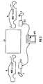
- FIG. 2 shows a device for backing up the information on a mobile data memory MDS, which is accommodated in a car body K and accompanies it during the entire assembly. All information about the resulting vehicle is stored in the mobile data memory MDS, for example the color, the type of engine, the tire size, equipment features, etc.
- the body K has just left the paint shop and is supposed to pass through the drying oven O. Since the mobile data storage device MDS in the drying oven O is exposed to temperatures above 200 ° C for several hours, the temperature inside the housing G will be higher than 120 ° C. At this temperature, however, the memory module (which can be a RAM or an EEPROM) in the mobile data memory MDS loses its data content.
- the memory module which can be a RAM or an EEPROM
- a first and a second read / write device SL1, SL2 are provided at the entrance and at the exit of the drying oven O and are connected to a central data processing system PLC.
- the car body K passes the first read-write device SL1
- the information from the read-write memory RAM of the mobile data memory MDS and the hard-coded information are read from the hard-coded information area ROM and stored in the data processing system PLC.
- the information from the mobile data memory is read again via the second read / write device SL2 and compared with the information located in the data processing system PLC.
- the faulty or all of the information can be written back into the mobile data memory MDS via the read / write device SL2.
- the hard-coded information in the mobile data memory MDS ensures that the information previously stored in the data processing system SPS is assigned to the correct mobile data memory MDS, since the hard-coded information is not lost even due to the high temperatures in the drying oven O.
- the optical identifier 111 known from FIG. 1 can also be applied to the housing G. This identifier could then be read by an optical reading device, for example a video chamber V, and then identified. As an optical However, a barcode could also be used for the identifier, which could then be read by a barcode reader.
Landscapes
- Engineering & Computer Science (AREA)
- Physics & Mathematics (AREA)
- General Physics & Mathematics (AREA)
- Automation & Control Theory (AREA)
- General Engineering & Computer Science (AREA)
- Manufacturing & Machinery (AREA)
- Quality & Reliability (AREA)
- General Factory Administration (AREA)
- Storage Device Security (AREA)
Abstract
Description
- Zur Identifizierung und Bearbeitung von beliebigen Gegenständen, beispielsweise von Werkstücken oder Teilprodukten in Produktionslinien, wird dem jeweiligen Gegenstand ein sogenannter mobiler Datenträger zugeordnet. Dieser mobile Datenträger verfügt unter anderem über eine Speichervorrichtung in der alle den Gegenstand betreffenden produktionsrelevanten Daten hinterlegt sind oder nach Abschluß bestimmter Bearbeitungsvorgänge neu hinterlegt werden. Die Änderung oder Ab frage der Daten im Speicher des mobilen Datenträgers erfolgt mittels drahtloser Übertragungstechnik durch Schreib-Lese-Geräte, die an den verschiedensten Stellen einer Produktionslinie vorgesehen sein können.
- Wenn durch defekte Speicherbausteine (RAM oder EEPROM) oder durch äußere Einflüsse, wie zu hohe Temperaturen, diese Daten verloren gehen, kann es zum Produktionsstillstand kommen. Dieser muß dann durch eine Notstrategie möglichst schnell behoben werden. Bisher wurde dieses Problem durch Handeingabe über Terminals gelöst. Diese Lösung ist jedoch aufwendig und zeitintensiv.
- Aufgabe der Erfindung ist es, ein automatisiertes Verfahren zur Datensicherung von beschreib- und lesbaren Datenträgern sowie einen dafür geeigneten Datenträger zu schaffen.
- Diese Aufgabe wird durch ein Verfahren gelöst, bei dem jedem Datenträger eine festcodierte Kennung zugeordnet wird und bei Gefahr eines Datenverlust diese Kennung zusammen mit den Daten des Datenträgers von einer Lesevorrichtung gelesen werden, wobei nach der Gefahr des Datenverlusts die vorher gelesenen Daten von einer Schreibvorrichtung in den Datenträger mit der entsprechenden Kennung geschrieben werden.
- Bei einer vorteilhaften, zeitsparenden Ausbildung der Erfindung werden nach der Gefahr des Datenverlust die Daten des Datenträgers mit den zuvor gelesenen überprüft und nur die fehlerhaften Daten neu überschrieben.
- Falls selbst die festcodierte Information verloren gehen sollte, ist es vorteilhaft, wenn auf dem Datenträger eine optisch lesbare Kennung aufgebracht ist, die dann zusammen mit den Daten des Datenträgers von der Schreib-Lese-Vorrichtung gelesen werden kann.
- Ein zur Durchführung des Verfahrens geeigneter Datenträger verfügt über einen Schreib-Lese-Speicher und mindestens einem festcodierbaren Informationsbereich der beispielsweise als Widerstandsmatrix oder als Diodenmatrix ausgebildet sein kann.
- Der Datenträger kann aber auch anstatt des festcodierbaren Informationsbereichs mit einer optisch lesbar aufgebrachten Kennung versehen sein. Zur Erhöhung der Datensicherheit ist eine Kombination aus einem festcodierbaren Informationsbereich und einer optisch lesbaren Kennung vorteilhaft.
- Eine Ausbildung der Erfindung wird im folgenden anhand einer Zeichnung näher erläutert. Dabei zeigen:
- FIG 1 ein Identifikationssystem,
- FIG 2 eine Anordnung zur Ausführung des Verfahrens.
- FIG 1 zeigt ein Automatisierungsgerät SPS, wie es beispielsweise bei speicherprogrammierbaren Steuerungen verwendet wird. Das Automatisierungsgerät SPS ist über ein Kabel K mit einer Schreib-Lese-Vorrichtung SL verbunden. Neben der Schreib-Lese-Vorrichtung SL ist ein mobiler Datenträger MDS dargestellt, der beispielsweise einer Autokarosserie auf dem Weg durch die Montagelinie fest zugeordnet ist. Der mobile Datenspeicher MDS könnte aber auch, einem nicht gezeigten Werkstück zugeordnet oder an einer Palette angebracht sein. Durch den Doppelpfeil unterhalb des mobilen Datenträgers ist angedeutet, daß dieser an verschiedenen Stellen der Montage- oder Produktionslinie an einer Schreib-Lese-Vorrichtung SL vorbeigeführt wird.
- Das Automatisierungsgerät SPS verfügt unter anderem über eine Steuerbaugruppe B, die für den Informationsaustausch mit der Schreib-lese-Vorrichtung SL zuständig ist. Die Schreib-lese-Vorrichtung SL weist einen Modulator M1 und eine daran angeschlossene Sendeantenne A1 auf. Der mobile Datenträger MDS verfügt über einen Modulator M2 und eine diesem zugeordnete Antenne A2. Der Modulator M2 sowie der Schreib-Lese-Speicher RAM ist an eine Steuereinheit P, die beispielsweise als ASIC ausgeführt sein kann, angeschlossen. Über die Steuereinheit P kann der Schreib-Lese-Speicher RAM beschrieben und gelesen werden; außerdem steuert sie die Sende- und Empfangsvorgänge über die Antenne A1.
- Das Automatisierungsgerät SPS gibt die produktionsrelevanten Daten für den jeweiligen Gegenstand, beispielsweise für eine Autokarosserie, an das Schreib-Lese-Gerät SL. Soll der Speicher RAM des mobilen Datenspeichers MDS ganz oder teilweise neu beschrieben werden, so werden die entsprechenden Befehle und Daten vom Automatisierungsgerät SPS über den Modulator MS und die Antenne A1 des Schreib-Lese-Gerätes SL an den mobilen Datenspeicher D gesendet. Dieser empfängt mit seiner Antenne A2 die Informationen und gibt sie über den Demodulator M2 und die interne Steuereinheit P an den Speicher RAM weiter.
- Die elektronischen Bauteile des mobilen Datenspeichers MDS sind in einem Gehäuse G untergebracht, wodurch sie von äußeren Einflüssen, wie Temperatur, Erschütterungen, Beschädigungen, etc., in gewissem Maße geschützt sind. Auf dem Gehäuse G ist im unteren Bereich eine optisch lesbare Nummer 111 fest eingepräft.
- FIG 2 zeigt eine Vorrichtung zur Sicherungen der Informationen auf einem mobilen Datenspeicher MDS, der in einer Autokarosserie K untergebracht ist und diese während der gesamten Montage begleitet. In dem mobilen Datenspeicher MDS sind sämtliche Informationen über das entstehende Fahrzeug abgelegt, beispielsweise die Farbe, die Art der Motorisierung, die Reifengröße, Ausstattungsmerkmale, etc.. Die Karosserie K habe soeben die Lackiererei verlassen und soll den Trockenofen O passieren. Da der mobile Datenspeicher MDS im Trockenofen O über mehrere Stunden Temperaturen über 200° C ausgesetzt ist, wird sich im Innern seines Gehäuses G eine Temperatur einstellen, die höher als 120° C ist. Bei dieser Temperatur verliert jedoch der Speicherbaustein (der ein RAM oder auch ein EEPROM sein kann) im mobilen Datenspeicher MDS seinen Dateninhalt.
- Zur Sicherung der Information ist am Eingang und am Ausgang des Trockenofens O ein erstes und zweites Schreib-Lese-Gerät SL1, SL2 vorgesehen, das mit einer zentralen Datenverarbeitungsanlage SPS verbunden ist. Wenn die Karaosserie K das erste Schreib-Lese-Gerät SL1 passiert, werden die Informationen aus dem Schreib-Lese-Speicher RAM des mobilen Datenspeichers MDS und die festcodierte Information aus dem festcodierten Informationsbereich ROM gelesen und in der Datenverarbeitungsanlage SPS abgelegt. Wenn das Fahrzeug den Trockenofen O verläßt, wird über das zweite Schreib-Lese-Gerät SL2 wieder die Information aus dem mobilen Datenspeicher gelesen und mit den Informationen die sich in der Datenverarbeitungsanlage SPS befinden, verglichen. Stellen sich dabei einige oder alle Informationen als fehlerhaft heraus, so können die fehlerhaften oder alle Informationen über das Schreib-lese-Gerät SL2 wieder in den mobilen Datenspeicher MDS eingeschrieben werden. Jedenfalls ist durch die festcodierte Information im mobilen Datenspeicher MDS sichergestellt, daß die zuvor in der Datenverarbeitungsanlage SPS gespeicherten Informationen dem richtigen mobilen Datenspeicher MDS zugeordnet werden, da die festcodierte Information auch durch die hohen Temperaturen im Trockenofen O nicht verloren geht.
- Bei einer anderen Ausführungsvariante kann darauf verzichtet werden zunächst die Daten aus dem mobilen Datenspeicher MDS nach Verlassen des Trockenbereichs O zu lesen. Es kann vielmehr sofort ein Schreibvorgang eingeleitet werden der die alten Informationen im mobilen Datenspeicher, unabhängig davon ob diese noch stimmen oder bereits verfälscht worden sind, mit den zuvor gelesenen Informationen überschreibt.
- Anstelle der festcodierten Information im mobilen Datenspeicher MDS oder als zusätzliches Sicherheitskriterium, kann auf dem Gehäuse G auch die aus FIG 1 bekannte optische Kennung 111 aufgebracht sein. Diese Kennung könnte dann von einem optischen Lesegerät beispielsweise einer Videokammera V gelesen und anschließend identifiziert werden. Als optische Kennung könnte aber auch ein Strichcode (Barcode) verwendet werden, der dann von einem Strichcodeleser gelesen werden könnte.
Claims (8)
- Verfahren zur Datensicherung von beschreib- und lesbaren Datenträgern, insbesondere von mobilen Datenspeichern (MDS), wobei1.1 jedem Datenträger (MDS) eine festcodierte Kennung zugeordnet wird,1.2 bei Gefahr eines Datenverlusts die Kennung zusammen mit den Daten des Datenträgers (MDS) von einer Lese-Vorrichtung (SL1) gelesen werden,1.3 nach der Gefahr des Datenverlusts die vorher gelesenen Daten von einer Schreibvorrichtung (SL2) in den Datenträger (MDS) mit der entsprechenden Kennung geschrieben werden.
- Verfahren nach Anspruch 1, wobei nach der Gefahr des Datenverlusts die Daten des Datenträgers (MDS) mit den vorher zuvor gelesenen überprüft werden und nur die fehlerhaften Daten neu überschrieben werden.
- Verfahren nach einem der vorstehenden Ansprüche, wobei auf dem Datenträger (MDS) eine optisch lesbare Kennung (111) vorgesehen ist, die von Schreib-Lese-Vorrichtungen (SL1,SL2) identifizierbar ist.
- Datenträger, insbesondere mobiler Datenspeicher (MDS), mit einem Schreib-Lese-Speicher (RAM) und mindestens einem festcodierbaren Informationsbereich (ROM).
- Datenträger, insbesondere mobiler Datenspeicher (MDS), mit einem Schreib-Lese-Speicher (RAM) und mit mindestens einer optisch lesbar aufgebrachten Kennung (111).
- Datenträger, insbesondere mobiler Datenspeicher (MDS), mit einem Schreib-Lese-Speicher (RAM), und mindestens einem festcodierbaren Informationsbereich (ROM) und mit einer optisch lesbar aufgebrachten Kennung (111).
- Vorrichtung zur Durchführung des Verfahrens mit mindestens einem Schreib-Lese-Gerät (SL1,SL2) zum Beschreiben und Lesen der Informationen der Datenträger (MDS) nach den Ansprüchen 4 bis 6 und einer mit dem Schreib-Lese-Gerät (SL1,SL2) verbundenen Datenverarbeitungsanlage (SPS).
- Vorrichtung nach Anspruch 7, wobei die Schreib-Lese-Geräte (SL1,SL2) über Mittel (V) zur Erkennung von optisch lesbaren Zeichen verfügen.
Applications Claiming Priority (2)
| Application Number | Priority Date | Filing Date | Title |
|---|---|---|---|
| DE4228083 | 1992-08-24 | ||
| DE4228083 | 1992-08-24 |
Publications (3)
| Publication Number | Publication Date |
|---|---|
| EP0584657A2 true EP0584657A2 (de) | 1994-03-02 |
| EP0584657A3 EP0584657A3 (en) | 1995-10-11 |
| EP0584657B1 EP0584657B1 (de) | 1998-06-03 |
Family
ID=6466294
Family Applications (1)
| Application Number | Title | Priority Date | Filing Date |
|---|---|---|---|
| EP93112898A Expired - Lifetime EP0584657B1 (de) | 1992-08-24 | 1993-08-11 | Verfahren und Vorrichtung zur Datensicherung in mobilen beschreib- und lesbaren Datenträgern |
Country Status (3)
| Country | Link |
|---|---|
| EP (1) | EP0584657B1 (de) |
| DE (1) | DE59308637D1 (de) |
| ES (1) | ES2117683T3 (de) |
Cited By (1)
| Publication number | Priority date | Publication date | Assignee | Title |
|---|---|---|---|---|
| WO2017012760A1 (de) * | 2015-07-20 | 2017-01-26 | Siemens Aktiengesellschaft | Verfahren zum bearbeiten von werkstücken |
Families Citing this family (1)
| Publication number | Priority date | Publication date | Assignee | Title |
|---|---|---|---|---|
| DE19947798A1 (de) * | 1999-10-05 | 2001-04-12 | Kurt Janus | Passiver Antennenreflexionsverstärker |
Family Cites Families (3)
| Publication number | Priority date | Publication date | Assignee | Title |
|---|---|---|---|---|
| US4776464A (en) * | 1985-06-17 | 1988-10-11 | Bae Automated Systems, Inc. | Automated article handling system and process |
| NL8503410A (nl) * | 1985-12-11 | 1987-07-01 | Philips Nv | Inrichting voor het overdragen van informatie tussen een elektronische geheugenkaart en een dataverwerkende eenheid. |
| JPS63226752A (ja) * | 1987-03-16 | 1988-09-21 | Omron Tateisi Electronics Co | Idシステムのデ−タ書込み方式 |
-
1993
- 1993-08-11 DE DE59308637T patent/DE59308637D1/de not_active Expired - Fee Related
- 1993-08-11 EP EP93112898A patent/EP0584657B1/de not_active Expired - Lifetime
- 1993-08-11 ES ES93112898T patent/ES2117683T3/es not_active Expired - Lifetime
Cited By (1)
| Publication number | Priority date | Publication date | Assignee | Title |
|---|---|---|---|---|
| WO2017012760A1 (de) * | 2015-07-20 | 2017-01-26 | Siemens Aktiengesellschaft | Verfahren zum bearbeiten von werkstücken |
Also Published As
| Publication number | Publication date |
|---|---|
| EP0584657A3 (en) | 1995-10-11 |
| ES2117683T3 (es) | 1998-08-16 |
| DE59308637D1 (de) | 1998-07-09 |
| EP0584657B1 (de) | 1998-06-03 |
Similar Documents
| Publication | Publication Date | Title |
|---|---|---|
| DE3802056C2 (de) | Verfahren und Vorrichtung zur Identifizierung von Werkstücken | |
| DE19843151C2 (de) | Bearbeitungsvorrichtung mit mindestens einem Bearbeitungswerkzeug | |
| DE2913999C2 (de) | Einrichtung zum Prüfen von Systemprogrammen numerischer Steuerungen für Werkzeugmaschinen | |
| CH654790A5 (de) | Verfahren zur aufzeichnung von daten auf ausweiskarten und vorrichtung zur durchfuehrung des verfahrens. | |
| WO2003045529A1 (de) | Vorrichtung, verfahren und computerprogrammprodukt zur durchführung eines filtrationsprozesses von fluiden | |
| DE3543996C2 (de) | Verfahren und Vorrichtung zur Anpassung eines Mehrrechnersystems an verschiedene Anwendungsbedingungen | |
| DE3227292A1 (de) | Elektronische steuereinrichtung | |
| DE10314260A1 (de) | Vorrichtung, System und Verfahren zur fertigungsbegleitenden, stückindividuellen Kennzeichnung von transportablen Gegenständen und zur Steuerung der Abläufe in Produktionsprozessen | |
| EP0584657B1 (de) | Verfahren und Vorrichtung zur Datensicherung in mobilen beschreib- und lesbaren Datenträgern | |
| EP0437551B1 (de) | Verfahren und vorrichtung zum abfragen von steuergeräte-daten | |
| DE69504484T2 (de) | Produktionseinrichtung und verarbeitungsbetrieb | |
| DE102013108277A1 (de) | Verfahren und System zum Kennzeichnen von Bauteilen in einer Fertigungsstraße | |
| DE102004025663A1 (de) | Verfahren und System zur Vollständigkeitsprüfung in einem Paket | |
| DE102022122567A1 (de) | Verfahren zur automatisierten Überwachung von zu transportierenden Waren | |
| WO2009015952A1 (de) | Verfahren zum betreiben eines tachographen und tachograph | |
| DE69806459T2 (de) | Verfahren zur Wiederaufbereitung für nicht mehr gebrauchsfähige Kraftfahrzeuge und Wiederaufbereitungsanlage zur Durchführung des Verfahrens | |
| EP4230443B1 (de) | Verfahren zur positionsbestimmung eines fahrzeugreifens | |
| DE3149926A1 (de) | Programmierbare vergleichsschaltung | |
| EP2081157B1 (de) | Elektroniches Wartungsbuch und Verfahren zum Betreiben eines elektronischen Wartungsbuchs | |
| DE69804257T2 (de) | System zur Charakterisierung eines Steuerrechners eines Antiblockiersystems für Kraftfahrzeugräder | |
| EP3990374A1 (de) | Verfahren, vorrichtung und system zur konfektionierung eines elektrischen kabels | |
| EP0238506B1 (de) | Verfahren zum automatischen, rechnergesteuerten umrüsten von bearbeitungs- und/oder montagestationen einer fertigungsstrasse | |
| EP0353530B2 (de) | Verfahren zum Unterscheidbarmachen von elektronischen Schaltungen mit nichtflüchtigem Speicher | |
| EP0353660A2 (de) | Verfahren zur Fehlersicherung in Speichersystemen von Datenverarbeitungsanlagen, insbesondere Fernsprechvermittlungsanlagen | |
| DE4003954C1 (de) |
Legal Events
| Date | Code | Title | Description |
|---|---|---|---|
| PUAI | Public reference made under article 153(3) epc to a published international application that has entered the european phase |
Free format text: ORIGINAL CODE: 0009012 |
|
| AK | Designated contracting states |
Kind code of ref document: A2 Designated state(s): BE DE ES FR GB IT |
|
| PUAL | Search report despatched |
Free format text: ORIGINAL CODE: 0009013 |
|
| AK | Designated contracting states |
Kind code of ref document: A3 Designated state(s): BE DE ES FR GB IT |
|
| RHK1 | Main classification (correction) |
Ipc: G06K 19/073 |
|
| 17P | Request for examination filed |
Effective date: 19960307 |
|
| R17P | Request for examination filed (corrected) |
Effective date: 19960306 |
|
| 17Q | First examination report despatched |
Effective date: 19970403 |
|
| GRAG | Despatch of communication of intention to grant |
Free format text: ORIGINAL CODE: EPIDOS AGRA |
|
| GRAG | Despatch of communication of intention to grant |
Free format text: ORIGINAL CODE: EPIDOS AGRA |
|
| GRAH | Despatch of communication of intention to grant a patent |
Free format text: ORIGINAL CODE: EPIDOS IGRA |
|
| RHK1 | Main classification (correction) |
Ipc: G06K 19/073 |
|
| GRAH | Despatch of communication of intention to grant a patent |
Free format text: ORIGINAL CODE: EPIDOS IGRA |
|
| GRAH | Despatch of communication of intention to grant a patent |
Free format text: ORIGINAL CODE: EPIDOS IGRA |
|
| GRAA | (expected) grant |
Free format text: ORIGINAL CODE: 0009210 |
|
| AK | Designated contracting states |
Kind code of ref document: B1 Designated state(s): BE DE ES FR GB IT |
|
| REF | Corresponds to: |
Ref document number: 59308637 Country of ref document: DE Date of ref document: 19980709 |
|
| ET | Fr: translation filed | ||
| ITF | It: translation for a ep patent filed | ||
| REG | Reference to a national code |
Ref country code: ES Ref legal event code: FG2A Ref document number: 2117683 Country of ref document: ES Kind code of ref document: T3 |
|
| GBT | Gb: translation of ep patent filed (gb section 77(6)(a)/1977) |
Effective date: 19980813 |
|
| PLBE | No opposition filed within time limit |
Free format text: ORIGINAL CODE: 0009261 |
|
| 26N | No opposition filed | ||
| REG | Reference to a national code |
Ref country code: GB Ref legal event code: IF02 |
|
| PGFP | Annual fee paid to national office [announced via postgrant information from national office to epo] |
Ref country code: GB Payment date: 20060808 Year of fee payment: 14 |
|
| PGFP | Annual fee paid to national office [announced via postgrant information from national office to epo] |
Ref country code: BE Payment date: 20060824 Year of fee payment: 14 |
|
| PGFP | Annual fee paid to national office [announced via postgrant information from national office to epo] |
Ref country code: ES Payment date: 20060912 Year of fee payment: 14 |
|
| PGFP | Annual fee paid to national office [announced via postgrant information from national office to epo] |
Ref country code: DE Payment date: 20071022 Year of fee payment: 15 |
|
| BERE | Be: lapsed |
Owner name: *SIEMENS A.G. Effective date: 20070831 |
|
| GBPC | Gb: european patent ceased through non-payment of renewal fee |
Effective date: 20070811 |
|
| PG25 | Lapsed in a contracting state [announced via postgrant information from national office to epo] |
Ref country code: BE Free format text: LAPSE BECAUSE OF NON-PAYMENT OF DUE FEES Effective date: 20070831 |
|
| REG | Reference to a national code |
Ref country code: ES Ref legal event code: FD2A Effective date: 20070813 |
|
| PG25 | Lapsed in a contracting state [announced via postgrant information from national office to epo] |
Ref country code: GB Free format text: LAPSE BECAUSE OF NON-PAYMENT OF DUE FEES Effective date: 20070811 |
|
| PGFP | Annual fee paid to national office [announced via postgrant information from national office to epo] |
Ref country code: IT Payment date: 20080828 Year of fee payment: 16 Ref country code: FR Payment date: 20080822 Year of fee payment: 16 |
|
| PG25 | Lapsed in a contracting state [announced via postgrant information from national office to epo] |
Ref country code: ES Free format text: LAPSE BECAUSE OF NON-PAYMENT OF DUE FEES Effective date: 20070813 |
|
| PG25 | Lapsed in a contracting state [announced via postgrant information from national office to epo] |
Ref country code: DE Free format text: LAPSE BECAUSE OF NON-PAYMENT OF DUE FEES Effective date: 20090303 |
|
| REG | Reference to a national code |
Ref country code: FR Ref legal event code: ST Effective date: 20100430 |
|
| PG25 | Lapsed in a contracting state [announced via postgrant information from national office to epo] |
Ref country code: FR Free format text: LAPSE BECAUSE OF NON-PAYMENT OF DUE FEES Effective date: 20090831 |
|
| PG25 | Lapsed in a contracting state [announced via postgrant information from national office to epo] |
Ref country code: IT Free format text: LAPSE BECAUSE OF NON-PAYMENT OF DUE FEES Effective date: 20090811 |