EP0584322B1 - Steuerzylinder für pneumatische steuergeräte mit signalkontakten - Google Patents
Steuerzylinder für pneumatische steuergeräte mit signalkontakten Download PDFInfo
- Publication number
- EP0584322B1 EP0584322B1 EP93905177A EP93905177A EP0584322B1 EP 0584322 B1 EP0584322 B1 EP 0584322B1 EP 93905177 A EP93905177 A EP 93905177A EP 93905177 A EP93905177 A EP 93905177A EP 0584322 B1 EP0584322 B1 EP 0584322B1
- Authority
- EP
- European Patent Office
- Prior art keywords
- guide rail
- groove
- control cylinder
- guiding
- guide
- Prior art date
- Legal status (The legal status is an assumption and is not a legal conclusion. Google has not performed a legal analysis and makes no representation as to the accuracy of the status listed.)
- Expired - Lifetime
Links
Images
Classifications
-
- F—MECHANICAL ENGINEERING; LIGHTING; HEATING; WEAPONS; BLASTING
- F15—FLUID-PRESSURE ACTUATORS; HYDRAULICS OR PNEUMATICS IN GENERAL
- F15B—SYSTEMS ACTING BY MEANS OF FLUIDS IN GENERAL; FLUID-PRESSURE ACTUATORS, e.g. SERVOMOTORS; DETAILS OF FLUID-PRESSURE SYSTEMS, NOT OTHERWISE PROVIDED FOR
- F15B15/00—Fluid-actuated devices for displacing a member from one position to another; Gearing associated therewith
- F15B15/20—Other details, e.g. assembly with regulating devices
- F15B15/28—Means for indicating the position, e.g. end of stroke
- F15B15/2892—Means for indicating the position, e.g. end of stroke characterised by the attachment means
-
- F—MECHANICAL ENGINEERING; LIGHTING; HEATING; WEAPONS; BLASTING
- F15—FLUID-PRESSURE ACTUATORS; HYDRAULICS OR PNEUMATICS IN GENERAL
- F15B—SYSTEMS ACTING BY MEANS OF FLUIDS IN GENERAL; FLUID-PRESSURE ACTUATORS, e.g. SERVOMOTORS; DETAILS OF FLUID-PRESSURE SYSTEMS, NOT OTHERWISE PROVIDED FOR
- F15B15/00—Fluid-actuated devices for displacing a member from one position to another; Gearing associated therewith
- F15B15/20—Other details, e.g. assembly with regulating devices
- F15B15/28—Means for indicating the position, e.g. end of stroke
-
- F—MECHANICAL ENGINEERING; LIGHTING; HEATING; WEAPONS; BLASTING
- F16—ENGINEERING ELEMENTS AND UNITS; GENERAL MEASURES FOR PRODUCING AND MAINTAINING EFFECTIVE FUNCTIONING OF MACHINES OR INSTALLATIONS; THERMAL INSULATION IN GENERAL
- F16B—DEVICES FOR FASTENING OR SECURING CONSTRUCTIONAL ELEMENTS OR MACHINE PARTS TOGETHER, e.g. NAILS, BOLTS, CIRCLIPS, CLAMPS, CLIPS OR WEDGES; JOINTS OR JOINTING
- F16B2200/00—Constructional details of connections not covered for in other groups of this subclass
- F16B2200/30—Dovetail-like connections
Definitions
- the invention relates to pneumatic control units with a control cylinder, which is equipped with signal or control contacts for contactless interrogation of the position of the control piston.
- the invention relates in particular to the control devices of the type mentioned, which are equipped with a control cylinder, on the outside of which controllable contacts, in particular so-called reed contacts or the like, are arranged magnetically or electronically by the piston of the control cylinder or parts connected to it which, as soon as the piston reaches a predetermined position, open electrical circuits or. shut down.
- Such reed contacts are usually housed in a housing which has guide elements with the aid of which it can be displaced in a guide on the outside of the cylinder in order to be able to adjust and adjust its position relative to the cylinder and thus to the movable control piston. It has proven effective to design such guides and guide elements as so-called dovetail guides, in which the dovetail-shaped guide elements of the reed contact housing can be inserted into adapted dovetail-shaped guide grooves from one of the two end faces of the control cylinder. As long as the control cylinder is equipped with only one contact there are no serious shortcomings with this type of training.
- the invention aims to provide a control cylinder for pneumatic control devices, primarily the design of the devices for holding and guiding the housing for a signal or interrogation contact, that is to say an embodiment which does not have such a defect and in particular a Inserting or replacing the housing in a dovetail guide groove of the control cylinder allows without changing the position of other control or signal contacts or. their housing becomes necessary.
- the cross-sectional area of the substantially trapezoidal guide rail of the contact housing has a shape that deviates from the trapezoidal cross-sectional area of the associated guide groove of the control cylinder which, with essentially the same height or depth of both elements (rail or groove), the width of the guide rail on the side adjacent to the contact housing is smaller than the gap width of the guide groove on its open side and in which the overall width of the guide rail is shortened to one dimension on one side is, which is determined by a circle around the one edge on the narrow side of the guide rail with a radius which is at the maximum equal to the gap width of the guide groove, the distance between the other edge on the narrow side of the guide rail from the diametrically opposite outer edge of the guide rail exceeds the width of the guide groove.
- the height of the guide rail should decrease towards the unabridged side of the guide rail.
- the inclination of the side surfaces of the guide rail can deviate from the inclination of the adjacent surfaces of the guide groove, in particular it can be reduced.
- the corresponding angle of the guide rail can be approximately 45 °.
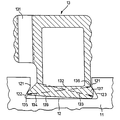
- control cylinder is designated 11.
- An essentially dovetail-shaped groove 12 is provided in the control cylinder, the dimensions of which correspond to conventional grooves for the attachment of reed contact housings.
- the housing according to the invention can be inserted into this groove, so that an exchange of conventional housings for the ones according to the invention is possible and both types can optionally be used simultaneously.
- the contact housing shown as a blank in section for receiving a reed contact consists of an extruded section 13 with a substantially rectangular cross section and a threaded bore 131 for receiving an adjusting screw, not shown.
- the lower side 132 of the housing 13 in the drawing is designed as a dovetail-shaped guide rail with an essentially trapezoidal cross section. Shape and size of this trapezoid, that of conventional dovetail guides substantially match the shape and size of the associated cross-sectional area of the guide groove, in the present case deviate from the shape and size of the trapezoidal area of the cross-section of the groove 12 of the control cylinder 11.
- the dimensions of this holding and guide rail 132 are determined by the dimensions of the guide groove 12 on the cylinder 11.
- the width of the guide rail on the side adjoining the housing 13 must be smaller by a certain amount than the width of the gap 121 of the guide groove 12, in order for the guide rail of the contact housing to be inside the groove according to FIG To be able to slide side to side.
- the trapezoidal cross-section which is in principle trapezoidal, must be shortened on the one side to the extent specified by the radius 133, the radius 133 being allowed to reach the maximum of the width of the gap 121.
- the distance 134 which the one outer edge 135 of the guide rail 132 has from the diametrically opposite inner edge 136 of the guide rail 132 must be greater than the width of the gap 121 of the guide groove 12.
- the contact housing 13 is inserted into the groove 12 with the outer edge 135 of the guide rail first, it can be pivoted past the outer edge 121 of the guide groove 12 with the shortened part 137 of the guide rail until the guide rail 132 touches the bottom of the guide groove 12 creates. If the adjusting screw (not shown) seated in the bore 131 is then tightened, it is supported on the top or.
- the outer surface of the control cylinder and forces the outer edge 135 of the guide rail upward, whereby it moves upwards on the side wall 122 of the groove and thereby pushes the shortened part 137 under the side wall 123 of the groove 12.
Landscapes
- Engineering & Computer Science (AREA)
- Physics & Mathematics (AREA)
- Fluid Mechanics (AREA)
- Mechanical Engineering (AREA)
- General Engineering & Computer Science (AREA)
- Actuator (AREA)
Abstract
Description
- Die Erfindung betrifft pneumatische Steuergeräte mit einem Steuerzylinder, der mit Signal- bzw. Steuerkontakten zur berührungslosen Abfrage der Stellung des Steuerkolbens ausgerüstet ist. Die Erfindung betrifft vor allem die Steuergeräte der besagten Art, die mit einem Steuerzylinder ausgerüstet sind, auf dessen Außenseite durch den Kolben des Steuerzylinders bzw. mit diesem verbundener Teile auf magnetischem oder elektronischem Wege steuerbare Kontakte, insbesondere sogenannte Reed-Kontakte oder dergleichen, angeordnet sind, die, sobald der Kolben eine vorgegebene Stellung erreicht, elektrische Stromkreise öffnen bzv. schließen.
- Derartige Reed-Kontakte sind üblicherweise in einem Gehäuse untergebracht, welches Führungselemente besitzt, mit Hilfe derer es in einer Führung auf der Außenseite des Zylinders verschiebbar ist, um seine Stellung gegenüber dem Zylinder und damit dem beweglichen Steuerkolben einstellen und justieren zu können. Es hat sich bewährt, derartige Führungen und Führungselemente als sogenannte Schwalbenschwanzführungen auszubilden, bei denen die schwalbenschwanzförmigen Führungselemente des Reed-Kontaktgehäuses von einer der beiden Stirnseiten des Steuerzylinders her in angepaßte schwalbenschwanzförmige Führungsnuten einführbar sind. Solange die Steuerzylinder mit nur einem Kontakt ausgerüstet sind, ergeben sich bei einer solchen Ausbildungsart keine schwerwiegenden Mängel. Sind jedoch zwei oder mehr Signal- oder Abfragekontakte für die Stellung des Steuerkolbens erforderlich, deren Stellung auf dem Steuerzylinder genau justiert sein muß, und fällt einer dieser Kontakte aus und muß ersetzt werden, müssen zusammen mit diesem in der Regel auch andere Kontakte ausgebaut, wieder eingebaut und in ihrer Stellung neu justiert werden.
- Die Erfindung bezweckt die Schaffung eines Steuerzylinders für pneumatische Steuereinrichtungen, und zwar in erster Linie die Ausbildung der Einrichtungen für die Halterung und Führung des Gehäuses für einen Signal- bzw. Abfrage-Kontakt, also einer Ausführungsform, die eine solchen Mangel nicht aufweist und insbesondere ein Einsetzen oder Auswechseln des Gehäuses in eine schwalbenschwanzförmige Führungsnut des Steuerzylinders ermöglicht, ohne daß eine Änderung der Stellung anderer Steuer- oder Signalkontakte bzv. ihrer Gehäuse erforderlich wird.
- Eine solche Aufgabe ist gemäß der Erfindung durch eine besondere Ausbildung der Führungselemente am Gehäuse des Reed-Kontaktes zu lösen, bei der die Querschnittsfläche der im wesentlichen trapezförmigen Führungsschiene des Kontakt-Gehäuses eine von der trapezförmigen Querschnittsfläche der zugehörigen Führungsnut des Steuerzylinders abweichende Form besitzt, bei der bei im wesentlichen gleicher Höhe bzw. Tiefe beider Elemente (Schiene bzw. Nut) die Breite der Führungsschiene an der dem Kontaktgehäuse benachbarten Seite geringer als die Spaltbreite der Führungsnut an deren offener Seite ist und bei der die Gesamtbreite der Führungsschiene einseitig auf ein Maß verkürzt ist, welches durch einen Kreis um die eine Kante an der Schmalseite der Führungsschiene mit einem Radius bestimmt wird, der im Maximum gleich der Spaltbreite der Führungsnut ist, wobei der Abstand der anderen Kante an der Schmalseite der Führungsschiene von der diametral gegenüberliegenden Außenkante der Führungsschiene die Breite der Führungsnut übersteigt.
- Um das Einsetzen der Führungsschiene des Kontaktgehäuses in die Führungsnut des Steuerzylinders zu erleichtern, sollte die Höhe der Führungsschiene zu der unverkürzten Seite der Führungsschiene hin abnehmen. Außerdem kann die Neigung der Seitenflächen der Führungsschiene von der Neigung der angrenzenden Flächen der Führungsnut abweichen, insbesondere verringert sein. Im konkreten Fall kann beispielsweise bei einem Winkel zwischen Seitenfläche und der Bodenfläche der Führungsnut von etwa 60° der entsprechende Winkel der Führungsschiene etwa 45° betragen.
- Die Erfindung soll an Hand eines Ausführungsbeispiels, das in der Zeichnung stark vergrößert mit den zum Verständnis wesentllichen Teilen dargestellt ist, erläutert werden, und zwar zeigt die Zeichnung den Gehäuserohling für den Kontakt mit den angrenzenden Teilen des ihn tragenden Steuerzylinders.
- In der Zeichnung ist der Steuerzylinder mit 11 bezeichnet. Im Steuerzylinder ist eine im wesentlichen schwalbenschwanzförmige Nut 12 vorgesehen, die in ihren Abmessungen herkömmlichen Nuten für die Anbringung von Reed-Kontakt-Gehäusen entspricht. Das erfindungsgemäße Gehäuse ist in diese Nut einsetzbar, so daß ein Austausch herkömmlicher Gehäuse gegen die erfindungsgemäßen möglich ist und wahlweise beide Arten gleichzeitig verwendbar sind.
- Das als Rohling im Schnitt dargestellte Kontaktgehäuse zur Aufnahme eines Reed-Kontaktes besteht aus einem Strangprofilabschnitt 13 mit im wesentlichen rechteckigem Querschnitt und einer Gevindebohrung 131 für die Aufnahme einer nicht dargestellten Stellschraube. Die in der Zeichnung untere Seite 132 des Gehäuses 13 ist als schwalbenschvanzförmige Führungsschiene mit im wesentlichen trapezförmigem Querschnitt ausgebildet. Form und Größe dieses Trapezes, die bei herkömmlichen Schwalbenschwanzführungen mit der Form und Größe der zugehörigen Querschnittsfläche der Führungsnut im wesentlichen übereinstimmen, weichen im vorliegenden Fall von der Form und Größe der Trapezfläche des Querschnitts der Nut 12 des Steuerzylinders 11 ab.
- Die Abmessungen dieser Halte- und Führungsschiene 132 werden durch die Abmessungen der Führungsnut 12 am Zylinder 11 bestimmt. Um die der Erfindung zu Grunde liegende Aufgabe zu lösen, muß die Breite der Führungsschiene an der an das Gehäuse 13 angrenzenden Seite um einen gewissen Betrag geringer als die Breite des Spaltes 121 der Führungsnut 12 sein, um die Führungsschiene des Kontaktgehäuses innerhalb der Nut nach der Seite hin und her schieben zu können. Außerdem muß der im Prinzip trapezförmige Querschnitt auf einer Seite in dem durch den Radius 133 vorgegebenen Ausmaß gekürzt sein, wobei der Radius 133 im Maximum an die Breite des Spaltes 121 heranreichen darf. Ferner muß der Abstand 134, den die eine Außenkante 135 der Führungsschiene 132 von der diametral gegenüberliegenden inneren Kante 136 der Führungsschiene 132 besitzt, größer als die Breite des Spaltes 121 der Führungsnut 12 sein.
- Wird bei solchen Abmessungen das Kontaktgehäuse 13 mit der Außenkante 135 der Führungsschiene voran in die Nut 12 eingesetzt, kann es mit dem verkürzten Teil 137 der Führungsschiene an der Außenkante 121 der Führungsnut 12 vorbei verschwenkt werden, bis sich die Führungsschiene 132 an den Boden der Führungsnut 12 anlegt. Wird dann die in der Bohrung 131 sitzende, nicht dargestellte Stellschraube angezogen, stützt sie sich auf der Oberseite bzv. Außenfläche des Steuerzylinders ab und zwingt die Außenkante 135 der Führungsschiene nach oben, wobei sie sich auf der Seitenwandung 122 der Nut aufwärts verschiebt und dadurch den verkürzten Teil 137 unter die Seitenwandung 123 der Nut 12 schiebt. Dadurch, daß die Außenfläche 139 als Unterseite der Führungsschiene zur Außenkante 135 hin ansteigend ausgebildet und damit die Höhe der Führungsschiene verringert ist, ergibt sich für das Einsetzen des Gehäuses 13 etwas mehr Spiel.
Claims (5)
- Steuerzylinder (11) für pneumatische Steuervorrichtungen mit in Form einer Schvalbenschvanz-Führung mit Führungsschiene (132) und Führungsnut (12) ausgebildeten Einrichtungen für die Halterung und Führung eines Gehäuses (13) für einen Reed-Kontakt oder dergleichen, dadurch gekennzeichnet, daß die Querschnittsfläche der im wesentlichen trapezförmigen Führungsschiene (132) des Reed-Kontakt-Gehäuses eine von der trapezförmigen Querschnittsfläche der zugehörigen Führungsnut (12) des Steuerzylinders (11) abweichende Form besitzt, bei der bei im wesentlichen gleicher Höhe bzv. Tiefe beider Elemente (Schiene bzv. Nut) die Breite der Führungsschiene (132) an der dem Kontaktgehäuse benachbarten Seite geringer als die Spaltbreite (121) der Führungsnut (12) an deren offener Seite ist und bei der die Gesamtbreite der Führungsschiene (132) einseitig auf ein Maß verkürzt ist, welches durch einen Kreis um die eine Kante an der Schmalseite der Führungsschiene (132) mit einem Radius (133) bestimmt wird, der im Maximum gleich der Spaltbreite (121) der Führungsnut (12) ist, wobei der Abstand (134) der anderen Kante an der Schmalseite der Führungsschiene (132) von der diametral gegenüberliegenden Außenkante (135) der Führungsschiene (132) die Spaltbreite (121) der Führungsnut (12) übersteigt.
- Steuerzylinder oder dergleichen nach Anspruch 1, dadurch gekennzeichnet, daß die Höhe der Führungsschiene (132) zu der unverkürzten Seite der Führungsschiene hin abnimmt.
- Steuerzylinder oder dergleichen nach Anspruch 1 oder 2, dadurch gekennzeichnet, daß die Neigung der Seitenflächen der Führungsschiene (132) von der Neigung der angrenzenden Flächen (122; 123) der Führungsnut (12) abweicht.
- Steuerzylinder oder dergleichen nach Anspruch 3, dadurch gekennzeichnet, daß die Neigung der Seitenflächen der Führungsschiene (132) im Vergleich zu der Neigung der Seitenflächen (122;123) der Führungsnut (12) bezogen auf deren Grundfläche verringert ist.
- Steuerzylinder oder dergleichen nach Anspruch 4, dadurch gekennzeichnet, daß bei einer Neigung der Seitenfläche (122;123) der Nut (12) von etwa 60° zur Bodenfläche dieser Nut die Neigung der Seitenflächen der Führungsschiene (132) etwa 45° beträgt.
Applications Claiming Priority (3)
| Application Number | Priority Date | Filing Date | Title |
|---|---|---|---|
| DE4207971 | 1992-03-13 | ||
| DE4207971A DE4207971A1 (de) | 1992-03-13 | 1992-03-13 | Steuerzylinder fuer pneumatische steuergeraete mit signalkontakten |
| PCT/DE1993/000221 WO1993018310A1 (de) | 1992-03-13 | 1993-03-10 | Steuerzylinder für pneumatische steuergeräte mit signalkontakten |
Publications (2)
| Publication Number | Publication Date |
|---|---|
| EP0584322A1 EP0584322A1 (de) | 1994-03-02 |
| EP0584322B1 true EP0584322B1 (de) | 1996-08-14 |
Family
ID=6453940
Family Applications (1)
| Application Number | Title | Priority Date | Filing Date |
|---|---|---|---|
| EP93905177A Expired - Lifetime EP0584322B1 (de) | 1992-03-13 | 1993-03-10 | Steuerzylinder für pneumatische steuergeräte mit signalkontakten |
Country Status (4)
| Country | Link |
|---|---|
| US (1) | US5438911A (de) |
| EP (1) | EP0584322B1 (de) |
| DE (2) | DE4207971A1 (de) |
| WO (1) | WO1993018310A1 (de) |
Families Citing this family (9)
| Publication number | Priority date | Publication date | Assignee | Title |
|---|---|---|---|---|
| DE4441758A1 (de) * | 1994-11-23 | 1996-05-30 | Siemens Ag | Verfahren und Vorrichtung zur Reduzierung von Oberschwingungs-Netzrückwirkungen eines selbstgeführten Multilevel-Wechselrichters |
| US5911762A (en) * | 1994-12-29 | 1999-06-15 | Ott; Reinhold | Anti-theft device |
| DE29518474U1 (de) * | 1995-11-21 | 1996-01-18 | Soyck GmbH, 58579 Schalksmühle | Schwalbenschwanzhalterung für Magnetfeldsensoren |
| AT405674B (de) * | 1997-04-08 | 1999-10-25 | Hygrama Ag | Pneumatischer oder hydraulischer zylinder |
| DE29819840U1 (de) | 1998-11-06 | 1999-03-04 | Pepperl & Fuchs GmbH, 68307 Mannheim | Haltevorrichtung für Sensoren |
| GB2375434B (en) * | 2001-03-09 | 2004-03-31 | Cne | Piston control |
| US6917515B2 (en) * | 2003-04-28 | 2005-07-12 | Kita Sensor Tech. Co., Ltd. | Electrical component having a housing retained in a receiving groove in a support through a retaining device |
| DE202008007384U1 (de) * | 2008-06-03 | 2009-10-29 | Sick Ag | Vorrichtung zur lösbaren Verbindung eines Sensors |
| JP6421444B2 (ja) * | 2014-04-30 | 2018-11-14 | Smc株式会社 | 位置検出センサ |
Family Cites Families (10)
| Publication number | Priority date | Publication date | Assignee | Title |
|---|---|---|---|---|
| US3577316A (en) * | 1969-01-06 | 1971-05-04 | Beloit Corp | Replaceable deflector blade structure for a papermaking machine |
| DE2319676A1 (de) * | 1973-04-18 | 1974-11-14 | Efen Elektrotech Fab | Halter zur geraetebefestigung |
| GB1448916A (en) * | 1974-10-01 | 1976-09-08 | Hego Electric Gmbh | Terminal block retaining member |
| IT8068705A0 (it) * | 1980-11-07 | 1980-11-07 | Firestone Europa S P A | Giunto smontabile a innesto e metodo per il collegamento a tenuta di un elemento in foglio ad un supporto |
| US4504168A (en) * | 1981-03-27 | 1985-03-12 | Miller Michael C | Connecting structure |
| DE69012313T2 (de) * | 1989-11-09 | 1995-04-27 | Charmilles Technologies | Numerisch gesteuerte maschine zum bearbeiten oder messen mit einer befestigungsvorrichtung für ein werkstück auf einem werktisch. |
| SE463684B (sv) * | 1989-12-22 | 1991-01-07 | Mecman Ab | Haallaranordning foer kolvlaegesavkaennare |
| DE4008529C1 (de) * | 1990-03-16 | 1991-08-14 | Hama Hamaphot Kg, Hanke & Thomas, 8855 Monheim, De | |
| DE4035627A1 (de) * | 1990-11-09 | 1992-05-14 | Bosch Gmbh Robert | Arbeitszylinder |
| DE9207582U1 (de) * | 1992-06-04 | 1992-08-20 | Festo KG, 7300 Esslingen | Gehäuse für einen Arbeitszylinder |
-
1992
- 1992-03-13 DE DE4207971A patent/DE4207971A1/de not_active Withdrawn
-
1993
- 1993-03-10 DE DE59303424T patent/DE59303424D1/de not_active Expired - Fee Related
- 1993-03-10 US US08/146,167 patent/US5438911A/en not_active Expired - Fee Related
- 1993-03-10 EP EP93905177A patent/EP0584322B1/de not_active Expired - Lifetime
- 1993-03-10 WO PCT/DE1993/000221 patent/WO1993018310A1/de not_active Ceased
Also Published As
| Publication number | Publication date |
|---|---|
| US5438911A (en) | 1995-08-08 |
| WO1993018310A1 (de) | 1993-09-16 |
| DE59303424D1 (de) | 1996-09-19 |
| EP0584322A1 (de) | 1994-03-02 |
| DE4207971A1 (de) | 1993-09-16 |
Similar Documents
| Publication | Publication Date | Title |
|---|---|---|
| DE3320809C2 (de) | ||
| DE69313708T2 (de) | Führungseinheit für geradlinige Wälzbewegung | |
| DE10316577A1 (de) | Linearführungsschienen-Haltevorrichtung | |
| DE3726157C2 (de) | ||
| DE3238336A1 (de) | Zylinder-messuhr | |
| DE4207971A1 (de) | Steuerzylinder fuer pneumatische steuergeraete mit signalkontakten | |
| DE3224065C2 (de) | Verstellbare Stranggießkokille für Vielfachstranggießanlagen | |
| DE3129182C2 (de) | Schaftbacke, insbesondere für Sportgewehre | |
| DE3328885C2 (de) | Vorrichtung für ein Magnetaufzeichnungsgerät zum Einstellen des Azimutes eines Magnetkopfes | |
| DE3604963C2 (de) | Einsatz zum Unterteilen einer Stranggießkokille | |
| DE8706196U1 (de) | Winkelschraubstock | |
| DE4039051C2 (de) | ||
| EP0423474B1 (de) | Vorrichtung zum lösbaren Verbinden von zwei Profilstäben | |
| DE2656543C2 (de) | Verstellbares Scharnier | |
| DE2210038A1 (de) | Fundamentbefestigung für Werkzeugmaschinenbetten | |
| EP0307347A1 (de) | Schlossschutzvorrichtung | |
| EP0455973A1 (de) | Führungsleiste für Aufzugstür | |
| DE4447345C1 (de) | Stufenlos einstellbare Unterlage für auf Werkzeugmaschinen zu bearbeitende Werkstücke | |
| EP0707808B1 (de) | Adapter | |
| DE7136475U (de) | Luftauslaßschiene für insbesondere Klima- und Lüftungsanlagen | |
| DE4238330C2 (de) | Schieberventil | |
| DE3022691A1 (de) | Arrondiervorrichtung fuer scharfkantige bandraender | |
| DE10018379A1 (de) | Einschub | |
| DE856625C (de) | Mechanische Einrichtung zur Herstellung elektrischer Verbindungen | |
| DE202023102798U1 (de) | Vorrichtung zur Montage von Schraubenkappen |
Legal Events
| Date | Code | Title | Description |
|---|---|---|---|
| PUAI | Public reference made under article 153(3) epc to a published international application that has entered the european phase |
Free format text: ORIGINAL CODE: 0009012 |
|
| AK | Designated contracting states |
Kind code of ref document: A1 Designated state(s): CH DE FR GB IT LI |
|
| 17P | Request for examination filed |
Effective date: 19940308 |
|
| 17Q | First examination report despatched |
Effective date: 19951024 |
|
| GRAH | Despatch of communication of intention to grant a patent |
Free format text: ORIGINAL CODE: EPIDOS IGRA |
|
| GRAH | Despatch of communication of intention to grant a patent |
Free format text: ORIGINAL CODE: EPIDOS IGRA |
|
| GRAA | (expected) grant |
Free format text: ORIGINAL CODE: 0009210 |
|
| AK | Designated contracting states |
Kind code of ref document: B1 Designated state(s): CH DE FR GB IT LI |
|
| REF | Corresponds to: |
Ref document number: 59303424 Country of ref document: DE Date of ref document: 19960919 |
|
| GBT | Gb: translation of ep patent filed (gb section 77(6)(a)/1977) |
Effective date: 19960906 |
|
| ITF | It: translation for a ep patent filed | ||
| ET | Fr: translation filed | ||
| PGFP | Annual fee paid to national office [announced via postgrant information from national office to epo] |
Ref country code: GB Payment date: 19970220 Year of fee payment: 5 |
|
| PGFP | Annual fee paid to national office [announced via postgrant information from national office to epo] |
Ref country code: FR Payment date: 19970328 Year of fee payment: 5 |
|
| PG25 | Lapsed in a contracting state [announced via postgrant information from national office to epo] |
Ref country code: LI Effective date: 19970331 Ref country code: CH Effective date: 19970331 |
|
| PLBE | No opposition filed within time limit |
Free format text: ORIGINAL CODE: 0009261 |
|
| STAA | Information on the status of an ep patent application or granted ep patent |
Free format text: STATUS: NO OPPOSITION FILED WITHIN TIME LIMIT |
|
| 26N | No opposition filed | ||
| REG | Reference to a national code |
Ref country code: CH Ref legal event code: PL |
|
| PG25 | Lapsed in a contracting state [announced via postgrant information from national office to epo] |
Ref country code: DE Effective date: 19971202 |
|
| PG25 | Lapsed in a contracting state [announced via postgrant information from national office to epo] |
Ref country code: GB Free format text: LAPSE BECAUSE OF NON-PAYMENT OF DUE FEES Effective date: 19980310 |
|
| PG25 | Lapsed in a contracting state [announced via postgrant information from national office to epo] |
Ref country code: FR Free format text: THE PATENT HAS BEEN ANNULLED BY A DECISION OF A NATIONAL AUTHORITY Effective date: 19980331 |
|
| GBPC | Gb: european patent ceased through non-payment of renewal fee |
Effective date: 19980310 |
|
| REG | Reference to a national code |
Ref country code: FR Ref legal event code: ST |
|
| PG25 | Lapsed in a contracting state [announced via postgrant information from national office to epo] |
Ref country code: IT Free format text: LAPSE BECAUSE OF NON-PAYMENT OF DUE FEES Effective date: 20050310 |