EP0583507A1 - Russfilter mit Heissgaserzeuger - Google Patents
Russfilter mit Heissgaserzeuger Download PDFInfo
- Publication number
- EP0583507A1 EP0583507A1 EP92120541A EP92120541A EP0583507A1 EP 0583507 A1 EP0583507 A1 EP 0583507A1 EP 92120541 A EP92120541 A EP 92120541A EP 92120541 A EP92120541 A EP 92120541A EP 0583507 A1 EP0583507 A1 EP 0583507A1
- Authority
- EP
- European Patent Office
- Prior art keywords
- hot gas
- gas generator
- inlet
- filter according
- fastened
- Prior art date
- Legal status (The legal status is an assumption and is not a legal conclusion. Google has not performed a legal analysis and makes no representation as to the accuracy of the status listed.)
- Granted
Links
- 239000004071 soot Substances 0.000 title claims abstract description 14
- 239000007789 gas Substances 0.000 claims abstract description 65
- 230000008929 regeneration Effects 0.000 claims description 25
- 238000011069 regeneration method Methods 0.000 claims description 25
- 238000002485 combustion reaction Methods 0.000 claims description 6
- 230000008878 coupling Effects 0.000 claims description 6
- 238000010168 coupling process Methods 0.000 claims description 6
- 238000005859 coupling reaction Methods 0.000 claims description 6
- 238000010438 heat treatment Methods 0.000 claims description 5
- 208000027418 Wounds and injury Diseases 0.000 description 4
- 239000000446 fuel Substances 0.000 description 4
- 230000006378 damage Effects 0.000 description 3
- 208000014674 injury Diseases 0.000 description 3
- 239000000919 ceramic Substances 0.000 description 2
- 239000002828 fuel tank Substances 0.000 description 2
- 229910000831 Steel Inorganic materials 0.000 description 1
- 238000004140 cleaning Methods 0.000 description 1
- 238000010276 construction Methods 0.000 description 1
- 238000001816 cooling Methods 0.000 description 1
- 238000006073 displacement reaction Methods 0.000 description 1
- 229930195733 hydrocarbon Natural products 0.000 description 1
- 150000002430 hydrocarbons Chemical class 0.000 description 1
- 238000004519 manufacturing process Methods 0.000 description 1
- 239000002245 particle Substances 0.000 description 1
- 238000003825 pressing Methods 0.000 description 1
- 230000000717 retained effect Effects 0.000 description 1
- 239000010959 steel Substances 0.000 description 1
- 238000004804 winding Methods 0.000 description 1
Images


Classifications
-
- F—MECHANICAL ENGINEERING; LIGHTING; HEATING; WEAPONS; BLASTING
- F01—MACHINES OR ENGINES IN GENERAL; ENGINE PLANTS IN GENERAL; STEAM ENGINES
- F01N—GAS-FLOW SILENCERS OR EXHAUST APPARATUS FOR MACHINES OR ENGINES IN GENERAL; GAS-FLOW SILENCERS OR EXHAUST APPARATUS FOR INTERNAL COMBUSTION ENGINES
- F01N3/00—Exhaust or silencing apparatus having means for purifying, rendering innocuous, or otherwise treating exhaust
- F01N3/02—Exhaust or silencing apparatus having means for purifying, rendering innocuous, or otherwise treating exhaust for cooling, or for removing solid constituents of, exhaust
- F01N3/021—Exhaust or silencing apparatus having means for purifying, rendering innocuous, or otherwise treating exhaust for cooling, or for removing solid constituents of, exhaust by means of filters
- F01N3/023—Exhaust or silencing apparatus having means for purifying, rendering innocuous, or otherwise treating exhaust for cooling, or for removing solid constituents of, exhaust by means of filters using means for regenerating the filters, e.g. by burning trapped particles
- F01N3/025—Exhaust or silencing apparatus having means for purifying, rendering innocuous, or otherwise treating exhaust for cooling, or for removing solid constituents of, exhaust by means of filters using means for regenerating the filters, e.g. by burning trapped particles using fuel burner or by adding fuel to exhaust
-
- B—PERFORMING OPERATIONS; TRANSPORTING
- B60—VEHICLES IN GENERAL
- B60S—SERVICING, CLEANING, REPAIRING, SUPPORTING, LIFTING, OR MANOEUVRING OF VEHICLES, NOT OTHERWISE PROVIDED FOR
- B60S5/00—Servicing, maintaining, repairing, or refitting of vehicles
-
- F—MECHANICAL ENGINEERING; LIGHTING; HEATING; WEAPONS; BLASTING
- F02—COMBUSTION ENGINES; HOT-GAS OR COMBUSTION-PRODUCT ENGINE PLANTS
- F02B—INTERNAL-COMBUSTION PISTON ENGINES; COMBUSTION ENGINES IN GENERAL
- F02B3/00—Engines characterised by air compression and subsequent fuel addition
- F02B3/06—Engines characterised by air compression and subsequent fuel addition with compression ignition
-
- Y—GENERAL TAGGING OF NEW TECHNOLOGICAL DEVELOPMENTS; GENERAL TAGGING OF CROSS-SECTIONAL TECHNOLOGIES SPANNING OVER SEVERAL SECTIONS OF THE IPC; TECHNICAL SUBJECTS COVERED BY FORMER USPC CROSS-REFERENCE ART COLLECTIONS [XRACs] AND DIGESTS
- Y10—TECHNICAL SUBJECTS COVERED BY FORMER USPC
- Y10S—TECHNICAL SUBJECTS COVERED BY FORMER USPC CROSS-REFERENCE ART COLLECTIONS [XRACs] AND DIGESTS
- Y10S55/00—Gas separation
- Y10S55/30—Exhaust treatment
Definitions
- the invention relates to a soot filter attached to the motor vehicle for diesel engines with a filter housing connected to the exhaust pipe, in which the filters are attached, which can be regenerated by hot gases.
- soot filter It is known to releasably attach the soot filter to the motor vehicle and to equip it without a burner, so that in particular at the end of the day the soot filter is removed from the motor vehicle and placed in a device which contains a burner which burns off the accumulated soot. Regularly loosening the filter from the motor vehicle and reattaching it later is a considerable workload and involves a risk of injury since the filter housings are very large after the motor vehicle arrives.
- the object of the invention is to provide a structurally simple, inexpensive and easy-to-handle soot filter system which has small external dimensions, offers a secure and tight hold and is short Regeneration time leads to a low workload.
- the filter housing attached to the motor vehicle instead of an internal hot gas generator has a connection to which an external mobile hot gas generator can be detachably connected and that the engine exhaust gas supply is closed when the hot gas generator is connected.
- the filter can always remain on the motor vehicle, since the particularly mobile regeneration device can be connected to the motor vehicle. Handling is easy and poses no risk of injury.
- the filter housing has small external dimensions and the entire filter is structurally simple and inexpensive to manufacture.
- connection of the filter housing has a branch which has a first inlet connected to the exhaust pipe, an outlet leading to the filter and a second inlet to which the hot gas generator can be detachably connected. This ensures safe and easy handling with a simple construction.
- a structurally particularly simple and easy and safe to handle design is created in that a pipe is attached to the hot gas generator, the free End is releasably attached to the branch, the first inlet being closed in the attached state.
- the first inlet can be closed by the pipe of the hot gas generator inserted into the second inlet.
- a resistance-free flow of the outlets during the journey and easy accessibility of the branch by the hot gas generator is provided if the second inlet is arranged transversely to the first inlet and to the outlet.
- the tube should have an outlet opening near its free end in the side wall, which opens towards the outlet. It is also advantageous if the wall of the tube closes the first inlet.
- the first inlet be arranged transversely to the second inlet and to the outlet.
- a high degree of flexibility and adaptability to exhaust pipes with different diameters is achieved if the pipe is connected to the hot gas generator via an intermediate coupling part.
- pipes of different diameters can be releasably attachable to the intermediate coupling part on the side facing away from the hot gas generator.
- the second inlet has an inside diameter that corresponds approximately to the outside diameter of the tube. It is of the greatest advantage if the branch has a recess on the inside, the inside diameter of which corresponds to the outside diameter of the tube and in which the free end of the tube lies. As a result, the hot gas generator is held securely, so that both hands are free for the user to open and close the closure.
- a structurally particularly simple and easy-to-use hot gas generator is created if it has an oil or gas burner, behind the combustion chamber of which a heating chamber is arranged in the gas flow direction, into which the flame gases pass and which has openings in the inner wall through which air can be supplied.
- the hot air generating burner is attached to the end of a flexible hose and / or a line which connects the burner with the carriage of the regeneration unit containing further components is particularly advantageous, the burner being detachable with a short connecting piece on the soot filter housing is attachable.
- the connecting hose between the mobile station and the motor vehicle filter housing is not flowed through by the hot gas, so that not only the risk of injury is further reduced, but also the hot gas reaches the filter at an optimally high temperature.
- a filter 1 is detachably attached to the motor vehicle and a regeneration unit 2 is arranged separately from the motor vehicle.
- the system is used on vehicles that visit a location to regenerate the filter once during a day.
- the size of the filter 1 is designed so that it has a loading time of 1.5 to 2 days. If the vehicle comes to the external stationary but mobile regeneration unit 2 at the end of the journey, the regeneration device is coupled to the filter via a thermally insulated, flexible hot gas hose 3. This is done using a quick release 4.
- the centerpiece of the regeneration unit 2 is a clean gas burner 5. It generates a hot gas of approximately 700-800 degrees from fresh air drawn in. This hot air flows through the filter 1 during regeneration and ignites the soot that has accumulated there. After about 5 to 7 minutes (depending on the filter size), the filter is burned free and the vehicle is ready for operation again. The regeneration unit 2 is then available for cleaning further filters.
- the filter 1 has a high-temperature-resistant housing 6 made of steel, in which ceramic wound filter candles are arranged.
- the exhaust gases enter the filter housing 6 and flow through the filter candles 7 therein.
- the particles of soot candles with their attached hydrocarbons are retained by the ceramic winding candles 7, so that only cleaned gas emerges from the filter 1.
- the filter can be adapted to any type of vehicle.
- the number of filter cartridges 7 depends on the vehicle-specific data such as displacement, performance and condition of the engine. On the basis of this data, the filter is dimensioned in such a way that it allows a 1.5 to 2-day loading period as required.
- a display in the driver's cab constantly signals the load status of the filter 1.
- the exhaust gas back pressure is a characteristic of the load status of the filter.
- the regeneration unit 2 has a clean gas burner 5, a component box 8, a fuel tank 9 and an operating unit 13.
- the hot gas burner 5 has a combustion chamber 14 which opens into a heating chamber 15 which is surrounded in a ring shape by an outer chamber 16. Fresh air is supplied to the outer chamber 16 and reaches the heating chamber 15 through openings 17 in the wall thereof. This optimizes combustion, flame progress and cooling.
- a thermally insulated hot gas hose 3 is fastened on the outlet side, which is connected to the loaded filter 1 via a quick-release fastener 4.
- a T-shaped tube 10 is attached to the filter inlet as a branch 19.
- a first inlet E1 serves to supply the exhaust gas to the filter, the other end 10b leads to the outside of the vehicle, forms a second inlet E2 there and is closed by a blind flange and a quick-release fastener 4. This end is thermally insulated. For the regeneration, the blind flange is removed and the hot gas hose 3 is attached.
- the filter remains on the vehicle - the inflow of the approximately 700-800 degrees hot air into the exhaust system facing the engine is prevented in a constructive way as follows:
- a pipe section 11 as a connecting pipe, which can be inserted into the pipe 10.
- the exhaust pipe 12 of the diesel engine opens laterally into the pipe 10 as the inlet E1, so that the mouth of the inlet E1 is closed when the pipe section 11 is inserted.
- the clean gas burner 5 is thermally insulated.
- the regeneration unit 2 is supplied with 220 volts, the electrical power consumption is approximately 1.2 kW.
- the regeneration unit sits in a mobile cabinet.
- the burner 5 can only be started when the hot gas hose 3 is flanged to the filter 1.
- the fuel required for combustion is removed from the fuel tank 9 by a pump.
- the combustion produces a heating output of approx. 25 kW with a fuel consumption of around 2 liters per hour.
- the regeneration time is between 5 and 7 minutes depending on the filter size.
- the vehicle-specific regeneration is automatically set by inserting a punch card into the operating unit 13.
- the lighting up of a lamp indicates the end of the regeneration time.
- the remaining regeneration time is shown on a digital display. This enables the operating personnel to estimate whether a regeneration that has already started should only be ended when the vehicle in question is immediately requested for a work assignment.
- a regeneration can be interrupted by pressing the stop button.
- a fuel gauge shows the fuel level.
- a thermometer attached to the filter emits the signal if the filter has been exposed to a temperature above 650 degrees for a sufficiently long period of time Resetting the load display in the cab.
- the burner 5 is not arranged inside or outside of the regeneration unit 2, but the burner 5 is fastened to the outer ends of the hose 3, which connects the regeneration unit 2 to the filter 1.
- the burner 5 is thus a portable, movable unit with an upper handle 18, which can be fastened to the filter housing 6 with its projecting connection (connecting pipe 11), as described above for the hose 3.
- the hose 3 is no longer flowed through by hot gases.
- the first inlet E1, exhaust gas inlet and outlet A (to the filter) are aligned with one another and the second inlet E2 (hot gas inlet) opens at a right angle between E1 and A.
- the hot gas generator 5 is thus at right angles to the tubes with its tube 11 of E1 and A inserted in the second inlet E2.
- the hot gas flows from the hot gas generator 5 via a lateral opening 11a in the tube 11 into the outlet A.
- the remaining tube wall of the tube 11 closes the first inlet E1.
- the branch 19 has a recess 21 on the inside, the inside diameter of which corresponds to the outside diameter of the tube 11 and in which the free end of the tube 11 lies.
- the pipe 11 is connected to the hot gas generator 5 via an intermediate coupling part 20.
- tubes 11 of different diameters can be detachably fastened to the intermediate coupling part 20 on the side facing away from the hot gas generator 5.
Abstract
Description
- Die Erfindung betrifft einen am Kraftfahrzeug befestigten Rußfilter für Dieselmotoren mit einem am Abgasrohr angeschlossenen Filtergehäuse, in dem die Filter befestigt sind, die durch Heißgase regenerierbar sind.
- Es ist bekannt, Rußfilter am Kraftfahrzeug lösbar zu befestigen und ohne Brenner auszustatten, so daß insbesondere am Tagesende der Rußfilter vom Kraftfahrzeug abgenommen und in eine Vorrichtung gesetzt wird, die einen Brenner enthält, der den angesammelten Ruß abbrennt. Das regelmäßige Lösen des Filters vom Kraftfahrzeug und spätere wieder Befestigen ist ein erheblicher Arbeitsaufwand und birgt eine Verletzungsgefahr, da die Filtergehäuse nach Ankunft des Kraftfahrzeugs sehr sind.
- Aufgabe der Erfindung ist es, ein konstruktiv einfaches, preiswertes und leicht handhabbares Rußfiltersystem zu schaffen, das kleine Außenabmessungen aufweist, einen sicheren und dichten Halt bietet und bei kurzer Regenerationszeit zu einem geringen Arbeitsaufwand führt.
- Diese Aufgabe wird erfindungsgemäß dadurch gelöst, daß das am Kraftfahrzeug befestigte Filtergehäuse statt eines internen Heißgaserzeugers einen Anschluß aufweist, an dem ein externer mobiler Heißgaserzeuger lösbar anschließbar ist und daß bei angeschlossenem Heißgaserzeuger die Motorenabgaszufuhr verschlossen ist.
- Hierdurch kann der Filter stets am Kraftfahrzeug verbleiben, da die insbesondere mobile Regenerierungsvorrichtung am Kraftfahrzeug anschließbar ist. Die Handhabung ist einfach und birgt insich keine Verletzungsgefahr. Das Filtergehäuse weist geringe Außenabmessungen auf und der gesamte Filter ist konstruktiv einfach und preiswert in der Herstellung.
- Da bei angeschlossenem Heißgaserzeuger die Motorenabgaszufuhr zum Filter verschlossen ist, wird selbstätig ausgeschlossen, daß die Heißgase in den Motor des Kraftfahrzeugs gelangen können. Durch das Verschließen des Abgasrohres des Motors wird auch erreicht, daß der Motor selbsttätig gestoppt wird und nicht mehr gestartet werden kann.
- Vorzugsweise wird hierbei vorgeschlagen, daß der Anschluß des Filtergehäuses eine Abzweigung aufweist, die einen am Abgasrohr angeschlossenen ersten Einlaß, einen zu dem Filter führenden Auslaß und einen zweiten Einlaß aufweist, an dem der Heißgaserzeuger lösbar anschließbar ist. Damit wird bei einfacher Konstruktion eine sichere und leichte Handhabung erreicht.
- Eine konstruktiv besonders einfache und leicht und sicher handhabbare Ausführung wird dadurch geschaffen, daß am Heißgaserzeuger ein Rohr befestigt ist, dessen freies Ende an der Abzweigung lösbar befestigt ist, wobei im befestigten Zustand der erste Einlaß verschlossen ist. Hierbei kann der erste Einlaß durch das in den zweiten Einlaß eingesteckte Rohr des Heißgaserzeugers verschlossen sein.
- Eine widerstandsfreie Strömung der Abgsse während der Fahrt und eine leichte Erreichbarkeit des Abzweigung durch den Heißgaserzeuger wird geschaffen, wenn der zweite Einlaß quer zum ersten Einlaß und zum Auslaß angeordnet ist. Hierbei sollte das Rohr nahe seines freien Ende in der Seitenwand eine Auslaßöffnung aufweisen, die sich zum Auslaß hin öffnet. Auch ist hierbei von Vorteil, wenn die Wand des Rohres den ersten Einlaß verschließt.
- Alternativ wird vorgeschlagen, daß der erste Einlaß quer zum zweiten Einlaß und zum Auslaß angeordnet ist.
- Eine hohe Flexibilität und Anpassungsfähigkeit an Abgasrohre mit verschieden großen Durchmessern wird erreicht, wenn das Rohr über ein Kupplungszwischenteil mit dem Heißgaserzeuger verbunden ist. Hierbei können am Kupplungszwischenteil auf der dem Heißgaserzeuger abgewandten Seite Rohre unterschiedlichen Durchmessers lösbar befestigbar sein.
- Eine gute Abdichtung wird erreicht, wenn der zweite Einlaß einen Innendurchmesser aufweist, der dem Außendurchmesser des Rohres etwa entspricht. Von größtem Vorteil ist es, wenn die Abzweigung innen eine Ausnehmung aufweist, deren Innendurchmesser dem Außendurchmesser des Rohres entspricht und in der das freie Ende des Rohres einliegt. Hierdurch wird der Heißgaserzeuger sicher gehalten, so daß für den Benutzer beide Hände frei sind, zum Öffnen und Schließen des Verschlusses.
- Ein konstruktiv besonders einfacher und leicht handhabbarer Heißgaserzeuger wird geschaffen, wenn er einen Öl- oder Gasbrenner aufweist, hinter dessen Brennkammer in Gasströmungsrichtung eine Erwärmungskammer angeordnet ist, in die die Flammgase gelangen und die in der Innenwand Öffnungen aufweist, durch die Luft zuführbar ist.
- Besonders vorteilhaft ist es, wenn der die Heißluft erzeugende Brenner am Ende eines flexiblen Schlauches und/oder einer Leitung befestigt ist, der bzw. die den Brenner mit dem weitere Komponenten enthaltenen Wagen der Regenerationseinheit verbindet, wobei der Brenner mit einem kurzen Anschlußstück am Rußfiltergehäuse lösbar befestigbar ist. Hierdurch wird der Verbindungsschlauch zwischen der mobilen Station und dem Kraftfahrzeugfiltergehäuse nicht vom Heißgas durchströmt, so daß nicht nur die Verletzungsgefahr weiter verringert wird, sondern auch das Heißgas mit optimal hoher Temperatur in den Filter gelangt.
- Vier Ausführungsbeispiele der Erfindung sind in den Zeichnungen in senkrechten Schnitten dargestellt und werden im folgenden näher beschrieben. Es zeigen:
- Figur 1:
- Ein erstes Ausführungsbeispiel mit am Kraftfahrzeug befestigtem Filter, bzw. Filtergehäuse, wobei das Kraftfahrzeug selber nicht dargestellt ist und
- Figur 2:
- ein zweites Ausführungsbeispiel.
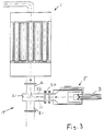
- Figur 3:
- Ein drittes Ausführungsbeispiel mit dünnerem Auspuffrohr.
- Figur 4:
- Das dritte Ausführungsbespiel mit dickerem Auspuffrohr.
- Beim erfindungsgemäßen Filtersystem mit externer Regeneration ist am Kraftfahrzeug ein Filter 1 lösbar befestigt und eine Regenerationseinheit 2 vom Kraftfahrzeug getrennt angeordnet. Das System wird verwendet bei Fahrzeugen, die während eines Tages einmal einen Standort zum Regenerieren des Filters anfahren. Die Größe des Filters 1 wird so ausgelegt, daß es eine Beladungsdauer von 1,5 bis 2 Tagen aufweist. Kommt das Fahrzeug am Fahrtende zur externen stationären, aber mobilen Regenerationseinheit 2, so wird über einen thermisch isolierten, flexiblen Heißgasschlauch 3 die Regenerationseinrichtung an das Filter angekoppelt. Dies geschieht über einen Schnellverschluß 4.
- Kernstück der Regenerationseinheit 2 ist ein Reingasbrenner 5. Er erzeugt aus angesaugter Frischluft ein Heißgas von etwa 700-800 Grad. Diese Heißluft strömt während der Regeneration durch das Filter 1 und entzündet den dort angesammelten Ruß. Nach etwa 5 bis 7 Minuten ist (je nach Filtergröße) das Filter freigebrannt und das Fahrzeug wieder betriebsbereit. Die Regenerationseinheit 2 steht danach zum Säubern weiterer Filter zur Verfügung.
- Das Filter 1 weist ein hochtemperaturbeständiges Gehäuse 6 aus Stahl auf, in dem Keramik-Wickelfilter-Kerzen angeordnet sind. Die Abgase treten in das Filtergehäuse 6 ein und durchströmen die darin befindlichen Filterkerzen 7. Die Partikel aus Rußkerzen mit ihren angelagerten Kohlenwasserstoffen werden durch die keramischen Wickelkerzen 7 zurückgehalten, so daß nur gereinigtes Gas aus dem Filter 1 austritt.
- Durch den modularen Aufbau des Filters 1 kann das Filter an jeden Fahrzeugtyp angepaßt werden. Hierbei richtet sich die Anzahl der Filterkerzen 7 nach den fahrzeugspezifischen Daten wie Hubraum, Leistung und Zustand des Motors. Anhand dieser Daten wird das Filter so dimensioniert, daß es je nach Bedarf eine 1,5 bis 2-tägige Beladungsdauer ermöglicht.
- Eine im Fahrerhaus angebrachte Anzeige signalisiert dem Fahrzeugführer ständig den Beladungszustand des Filters 1. Der Abgasgegendruck ist hierbei eine für den Beladungszustand des Filters charakteristische Größe.
- Die Regenerationseinheit 2 weist einen Reingasbrenner 5, eine Komponentenbox 8, einen Kraftstofftank 9 und eine Bedienungseinheit 13 auf. Der Heißgasbrenner 5 besitzt eine Brennkammer 14, die in eine Erwärmungskammer 15 mündet, die ringförmig von einer Außenkammer 16 umgeben ist. Der Außenkammer 16 wird Frischluft zugeführt, die über Öffnungen 17 in der Wand der Erwärmungskammer 15 in diese gelangt. Verbrennung, Flammenverlauf und Kühlung werden hierdurch optimiert.
- Am Reingasbrenner 5 ist ausgangsseitig ein thermisch isolierter Heißgasschlauch 3 befestigt, der über einen Schnellverschluß 4 an das beladene Filter 1 angeschlossen wird. Am Filtereingang ist ein T-förmiges Rohr 10 als Abzweigung 19 befestigt. Ein erster Einlaß E1 dient zur Zuführung des Abgases zum Filter, das andere Ende 10b ist zur Fahrzeugaußenseite hingeführt, bildet dort einen zweiten Einlaß E2 und ist durch einen Blindflansch und einen Schnellverschluß 4 verschlossen. Dieses Ende ist thermisch isoliert. Zur Regeneration wird der Blindflansch entfernt und der Heißgasschlauch 3 befestigt. Während der Regeneration verbleibt also das Filter am Fahrzeug - das Einströmen der etwa 700-800 Grad heißen Luft in den motorzugewandten Abgasstrang wird auf konstruktivem Wege wie folgt verhindert: Am Ende des Heißgas-Verbindungsschlauches 3 steht ein Rohrstück 11 als Anschlußrohr vor, das in das Rohr 10 einsteckbar ist. In das Rohr 10 mündet seitlich das Abgasrohr 12 des Dieselmotors als Einlaß E1, so daß bei eingestecktem Rohrstück 11 die Mündung des Einlasses E1 verschlossen ist.
- Wie der Heißgasschlauch 3 und das Filter 1 ist auch der Reingasbrenner 5 thermisch isoliert. Die Regenerationseinheit 2 wird mit 220 Volt versorgt, die elektrische Leistungsaufnahme beträgt etwa 1,2 kW. Die Regenerationseinheit sitzt in einem fahrbaren Schrank.
- Nur wenn der Heißgasschlauch 3 an den Filter 1 angeflanscht ist, läßt sich der Brenner 5 starten. Der zur Verbrennung notwendige Kraftstoff wird über eine Pumpe aus dem Kraftstofftank 9 entnommen. Bei der Verbrennung entsteht eine Heizleistung von ca. 25 kW bei einem Kraftstoffverbrauch von etwa 2 Liter pro Stunde. Die Regenerationszeit liegt je nach Filtergröße zwischen 5 und 7 Minuten.
- Durch Einschieben einer Lochkarte in die Bedienungseinheit 13 stellt sich automatisch die fahrzeugspezifische Regeneration ein. Das Aufleuchten einer Lampe zeigt das Ende der Regenerationszeit an. Während der Regeneration wird die noch verbleibende Regenerationszeit auf einer Digitalanzeige ausgegeben. Dies ermöglicht dem Bedienungspersonal abzuschätzen, ob eine bereits begonnene Regeneration erst beendet werden soll, wenn das betreffende Fahrzeug augenblicklich zu einem Arbeitseinsatz angefordert wird. das Unterbrechen einer Regeneration ist durch Drücken der Stop-Taste möglich. Eine Tankanzeige zeigt den Kraftstoffvorrat an. Ein am Filter sitzendes Thermometer gibt, falls das Filter über einen ausreichend langen Zeitraum einer Temperatur über 650 Grad ausgesetzt wurde, das Signal zum Resetten der Beladungsanzeige im Fahrerhaus.
- Im zweiten Ausführungsbeispiel nach Figur 2 ist der Brenner 5 nicht innerhalb oder außen an der Regenerationseinheit 2 angeordnet, sondern der Brenner 5 ist am äußeren Enden des Schlauches 3 befestigt, der die Regenerationseinheit 2 mit dem Filter 1 verbindet. Damit ist der Brenner 5 eine tragbare, bewegliche Einheit mit oberem Griff 18, die mit ihrem vorstehenden Anschluß (Anschlußrohr 11) am Filtergehäuse 6 in gleicher Weise befestigbar ist, wie oben zum Schlauch 3 beschrieben. Hierdurch ist der Schlauch 3 nicht mehr von Heißgasen durchströmt.
- Im dritten Ausführungsbeispiel nach Figur 3 und 4 fluchten erster Einlaß E1, Abgaseinlaß und Aulaß A (zum Filter) miteinander und der zweite Einlaß E2 (Heißgaseinlaß) mündet rechtwinklig zwischen E1 und A. Der Heißgaserzeuger 5 wird damit mit seinem Rohr 11 rechtwinklig zu den Rohren von E1 und A in den zweiten Einlaß E2 eingesteckt. Hierbei strömt das Heißgas von dem Heißgaserzeuger 5 über eine seitliche Öffnung 11a im Rohr 11 in den Auslaß A. Die übrige Rohrwandung des Rohrs 11 verschließt den ersten Einlaß E1.
- Die Abzweigung 19 weist innen eine Ausnehmung 21 auf, deren Innendurchmesser dem Außendurchmesser des Rohres 11 entspricht und in der das freie Ende des Rohres 11 einliegt. Das Rohr 11 ist über ein Kupplungszwischenteil 20 mit dem Heißgaserzeuger 5 verbunden. Hierdurch sind am Kupplungszwischenteil 20 auf der dem Heißgaserzeuger 5 abgewandten Seite Rohre 11 unterschiedlichen Durchmessers lösbar befestigbar.
Claims (14)
- Am Kraftfahrzeug befestigter Rußfilter (1) für Dieselmotoren mit einem am Abgasrohr (12) angeschlossenen Filtergehäuse (6), in dem die Filter (7) befestigt sind, die durch Heißgase regenerierbar sind, dadurch gekennzeichnet, daß das am Kraftfahrzeug befestigte Filtergehäuse (6) statt eines internen Heißgaserzeugers einen Anschluß (10) aufweist, an dem ein externer mobiler Heißgaserzeuger (5) lösbar anschließbar ist und daß bei angeschlossenem Heißgaserzeuger (5) die Motorenabgaszufuhr (12) verschlossen ist.
- Rußfilter nach Anspruch 2, dadurch gekennzeichnet, daß der Anschluß (10) des Filtergehäuses (6) eine Abzweigung (19) aufweist, die einen am Abgasrohr angeschlossenen ersten Einlaß (E1), einen zu dem Filter (1) führenden Auslaß (A) und einen zweiten Einlaß (E2) aufweist, an dem der Heißgaserzeuger (5) lösbar anschließbar ist.
- Rußfilter nach Anspruch 1 oder 2, dadurch gekennzeichnet, daß am Heißgaserzeuger (5) ein Rohr (11) befestigt ist, dessen freies Ende an der Abzweigung (19) lösbar befestigt ist, wobei im befestigten Zustand der erste Einlaß (E1) verschlossen ist.
- Rußfilter nach Anspruch 3, dadurch gekennzeichnet, daß der erste Einlaß (E1) durch das in den zweiten Einlaß (E2) eingesteckte Rohr (11) des Heißgaserzeugers (5) verschlossen ist.
- Rußfilter nach einem der Ansprüche 2 bis 4, dadurch gekennzeichnet, daß der zweite Einlaß (E2) quer zum ersten Einlaß (E1) und zum Auslaß (A) angeordnet ist.
- Rußfilter nach Anspruch 5, dadurch gekennzeichnet, daß das Rohr (11) nahe seines freien Ende in der Seitenwand eine Auslaßöffnung (11a) aufweist, die sich zum Auslaß (A) hin öffnet.
- Rußfilter nach Anspruch 5 oder 6, dadurch gekennzeichnet, daß die Wand des Rohres (11) den ersten Einlaß (E1) verschließt.
- Rußfilter nach einem der Ansprüche 1 bis 4, dadurch gekennzeichnet, daß der erste Einlaß (E1) quer zum zweiten Einlaß (E2) und zum Auslaß (A) angeordnet ist.
- Rußfilter nach einem der vorhergehenden Ansprüche 3 bis 8 , dadurch gekennzeichnet, daß das Rohr (11) über ein Kupplungszwischenteil (20) mit dem Heißgaserzeuger (5) verbunden ist.
- Rußfilter nach Anspruch 9, dadurch gekennzeichnet, daß am Kupplungszwischenteil (20) auf der dem Heißgaserzeuger (5) abgewandten Seite Rohre (11) unterschiedlichen Durchmessers lösbar befestigbar sind.
- Rußfilter nach einem der vorhergehenden Ansprüche 3 bis 10, dadurch gekennzeichnet, daß der zweite Einlaß (E2) einen Innendurchmesser aufweist, der dem Außendurchmesser des Rohres (11) etwa entspricht.
- Rußfilter nach einem der vorhergehenden Ansprüche 3 bis 11, dadurch gekennzeichnet, daß die Abzweigung (19) innen eine Ausnehmung (21) aufweist, deren Innendurchmesser dem Außendurchmesser des Rohres (11) entspricht und in der das freie Ende des Rohres (11) einliegt.
- Heißgaserzeuger zum Anschluß an einen Rußfilter nach einem der vorhergehenden Ansprüche, dadurch gekennzeichnet, daß er einen Öl- oder Gasbrenner aufweist, hinter dessen Brennkammer (14) in Gasströmungsrichtung eine Erwärmungskammer (15) angeordnet ist, in die die Flammgase gelangen und die in der Innenwand Öffnungen (17) aufweist, durch die Luft zuführbar ist.
- Heißgaserzeuger zum Anschluß an einen Rußfilter nach einem der vorhergehenden Ansprüche, dadurch gekennzeichnet, daß der die Heißluft erzeugende Heißgaserzeuger (5) am Ende eines flexiblen Schlauches (3) und/oder einer Leitung befestigt ist, der bzw. die den Brenner (5) mit dem weitere Komponenten enthaltenen Wagen der Regenerationseinheit (2) verbindet.
Applications Claiming Priority (2)
| Application Number | Priority Date | Filing Date | Title |
|---|---|---|---|
| DE4226901 | 1992-08-14 | ||
| DE4226901A DE4226901C2 (de) | 1992-08-14 | 1992-08-14 | Rußfilter mit Heißgaserzeuger |
Publications (2)
| Publication Number | Publication Date |
|---|---|
| EP0583507A1 true EP0583507A1 (de) | 1994-02-23 |
| EP0583507B1 EP0583507B1 (de) | 1996-03-27 |
Family
ID=6465529
Family Applications (1)
| Application Number | Title | Priority Date | Filing Date |
|---|---|---|---|
| EP92120541A Expired - Lifetime EP0583507B1 (de) | 1992-08-14 | 1992-12-02 | Russfilter mit Heissgaserzeuger |
Country Status (13)
| Country | Link |
|---|---|
| US (1) | US5394692A (de) |
| EP (1) | EP0583507B1 (de) |
| JP (1) | JPH06129232A (de) |
| KR (1) | KR940004181A (de) |
| AT (1) | ATE136096T1 (de) |
| BR (1) | BR9302712A (de) |
| DE (2) | DE4226901C2 (de) |
| DK (1) | DK0583507T3 (de) |
| ES (1) | ES2085538T3 (de) |
| GR (1) | GR3019950T3 (de) |
| HU (1) | HUT69859A (de) |
| SK (1) | SK396392A3 (de) |
| TW (1) | TW255942B (de) |
Families Citing this family (14)
| Publication number | Priority date | Publication date | Assignee | Title |
|---|---|---|---|---|
| DE4431567B4 (de) * | 1994-09-05 | 2004-04-08 | Deutz Ag | Partikelfilter |
| US5831530A (en) * | 1994-12-30 | 1998-11-03 | Lace Effect, Llc | Anti-theft vehicle system |
| US5598144A (en) * | 1994-12-30 | 1997-01-28 | Actodyne General, Inc. | Anti-theft vehicle system |
| US5989010A (en) | 1997-09-02 | 1999-11-23 | Thermatrix, Inc. | Matrix bed for generating non-planar reaction wave fronts, and method thereof |
| US6003305A (en) | 1997-09-02 | 1999-12-21 | Thermatrix, Inc. | Method of reducing internal combustion engine emissions, and system for same |
| US6471918B1 (en) | 2000-08-03 | 2002-10-29 | Starfire Systems, Inc. | Filter, regeneration and soot-removing systems and applications |
| JP2003129827A (ja) * | 2001-10-25 | 2003-05-08 | Komatsu Ltd | ディーゼルパティキュレートフィルタの取扱方法 |
| WO2005005797A2 (en) * | 2003-06-12 | 2005-01-20 | Donaldson Company, Inc. | Method of dispensing fuel into transient flow of an exhaust system |
| US20060101810A1 (en) * | 2004-11-15 | 2006-05-18 | Angelo Theodore G | System for dispensing fuel into an exhaust system of a diesel engine |
| KR100748660B1 (ko) * | 2005-12-13 | 2007-08-10 | 현대자동차주식회사 | 디젤 매연 필터의 재생 시스템 및 재생 방법 |
| DE102008045594B4 (de) * | 2008-09-03 | 2012-05-16 | Audi Ag | Verfahren und Vorrichtung zur Zudosierung eines Reduktionsmittels in einen Abgasstrang einer Brennkraftmaschine eines Fahrzeuges |
| DE102008047369A1 (de) * | 2008-09-15 | 2010-04-15 | Heraeus Sensor Technology Gmbh | Epitaktischer Rußsensor |
| JP2010223882A (ja) * | 2009-03-25 | 2010-10-07 | Ngk Insulators Ltd | フィルタ用連続再生試験装置及びフィルタの連続再生試験方法 |
| JP5650997B2 (ja) * | 2010-12-01 | 2015-01-07 | 日野自動車株式会社 | 排ガス浄化装置 |
Citations (3)
| Publication number | Priority date | Publication date | Assignee | Title |
|---|---|---|---|---|
| US4573317A (en) * | 1985-03-11 | 1986-03-04 | General Motors Corporation | Diesel exhaust cleaner and regeneration burner system with indexing particulate trap |
| DE3545437A1 (de) * | 1985-12-20 | 1987-07-02 | Eberspaecher J | Abgasreinigungsvorrichtung fuer dieselmotoren |
| US4899540A (en) * | 1987-08-21 | 1990-02-13 | Donaldson Company, Inc. | Muffler apparatus with filter trap and method of use |
Family Cites Families (6)
| Publication number | Priority date | Publication date | Assignee | Title |
|---|---|---|---|---|
| US4573319A (en) * | 1981-08-10 | 1986-03-04 | Clark Equipment Company | Vehicle hydraulic system with single pump |
| US4383411A (en) * | 1981-08-10 | 1983-05-17 | General Motors Corporation | Diesel exhaust cleaner with burner vortex chamber |
| JPS5976712U (ja) * | 1982-11-16 | 1984-05-24 | 三菱電機株式会社 | 排ガス微粒子除去装置 |
| US4494375A (en) * | 1983-02-03 | 1985-01-22 | Ford Motor Company | Filtration system for diesel engine exhaust-I |
| DE3729861C2 (de) * | 1987-09-05 | 1995-06-22 | Deutsche Forsch Luft Raumfahrt | Verfahren zum Betreiben einer Rußfiltervorrichtung für einen Dieselmotor und Rußfiltervorrichtung zur Durchführung dieses Verfahrens |
| DE4026375C1 (de) * | 1990-08-21 | 1992-01-30 | Fa. J. Eberspaecher, 7300 Esslingen, De |
-
1992
- 1992-08-14 DE DE4226901A patent/DE4226901C2/de not_active Expired - Fee Related
- 1992-12-02 ES ES92120541T patent/ES2085538T3/es not_active Expired - Lifetime
- 1992-12-02 AT AT92120541T patent/ATE136096T1/de active
- 1992-12-02 DK DK92120541.5T patent/DK0583507T3/da active
- 1992-12-02 EP EP92120541A patent/EP0583507B1/de not_active Expired - Lifetime
- 1992-12-02 DE DE59205870T patent/DE59205870D1/de not_active Expired - Fee Related
- 1992-12-29 SK SK3963-92A patent/SK396392A3/sk unknown
-
1993
- 1993-01-13 HU HU9300074A patent/HUT69859A/hu unknown
- 1993-01-20 JP JP5007401A patent/JPH06129232A/ja active Pending
- 1993-02-12 TW TW082100997A patent/TW255942B/zh active
- 1993-03-16 KR KR1019930004021A patent/KR940004181A/ko active IP Right Grant
- 1993-05-27 US US08/068,244 patent/US5394692A/en not_active Expired - Fee Related
- 1993-06-30 BR BR9302712A patent/BR9302712A/pt not_active Application Discontinuation
-
1996
- 1996-05-17 GR GR960401317T patent/GR3019950T3/el unknown
Patent Citations (3)
| Publication number | Priority date | Publication date | Assignee | Title |
|---|---|---|---|---|
| US4573317A (en) * | 1985-03-11 | 1986-03-04 | General Motors Corporation | Diesel exhaust cleaner and regeneration burner system with indexing particulate trap |
| DE3545437A1 (de) * | 1985-12-20 | 1987-07-02 | Eberspaecher J | Abgasreinigungsvorrichtung fuer dieselmotoren |
| US4899540A (en) * | 1987-08-21 | 1990-02-13 | Donaldson Company, Inc. | Muffler apparatus with filter trap and method of use |
Also Published As
| Publication number | Publication date |
|---|---|
| DE4226901C2 (de) | 2002-03-07 |
| DE59205870D1 (de) | 1996-05-02 |
| ES2085538T3 (es) | 1996-06-01 |
| GR3019950T3 (en) | 1996-08-31 |
| US5394692A (en) | 1995-03-07 |
| DK0583507T3 (da) | 1996-07-29 |
| ATE136096T1 (de) | 1996-04-15 |
| SK396392A3 (en) | 1996-04-03 |
| DE4226901A1 (de) | 1994-02-17 |
| HUT69859A (en) | 1995-09-28 |
| KR940004181A (ko) | 1994-03-14 |
| TW255942B (de) | 1995-09-01 |
| BR9302712A (pt) | 1994-02-16 |
| HU9300074D0 (en) | 1993-04-28 |
| JPH06129232A (ja) | 1994-05-10 |
| EP0583507B1 (de) | 1996-03-27 |
Similar Documents
| Publication | Publication Date | Title |
|---|---|---|
| EP0583507B1 (de) | Russfilter mit Heissgaserzeuger | |
| DE2953010C2 (de) | ||
| EP1867848B1 (de) | Brennkraftmaschine mit Sekundärlufteinblassystem | |
| DE10029513B4 (de) | Verfahren und Vorrichtung zur Reduzierung von Ascherückständen in einem Partikelfilter | |
| DE102006000785A1 (de) | Filterservicesystem und -verfahren | |
| DE4007516A1 (de) | Dieselmotor | |
| DE102005062473A1 (de) | Filterservicesystem und -verfahren | |
| DE102013013663A1 (de) | Verfahren zum Betreiben einer Antriebseinrichtung sowie entsprechende Antriebseinrichtung | |
| DE102013001080A1 (de) | Verfahren zum Betreiben einer Antriebseinrichtung sowie entsprechende Antriebseinrichtung | |
| DE202014102809U1 (de) | Abgasmodul für eine Brennkraftmaschine | |
| DE102018220824A1 (de) | System zum zwangsweisen regenerieren eines benzinpartikelfilters | |
| DE19504450A1 (de) | Abgasreinigungsvorrichtung für Verbrennungskraftmaschinen | |
| DE4443133B4 (de) | Abgasnachbehandlungssystem eines ladedruckbetriebenen Verbrennungsmotors mit Partikelfilter und Brenner | |
| DE4134949A1 (de) | Verfahren und vorrichtung zur wartung und diagnose eines russfilters | |
| DE102008063809B4 (de) | Abgasreinigungsanlage sowie Verfahren zum Betrieb einer Abgasreinigungsanlage | |
| DE102020129001A1 (de) | Abgasanlage mit Abgasturbolader, Ejektor und Abgaskatalysator | |
| WO1995024546A1 (de) | Vorrichtung zur abgasreinigung bei brennkraftmaschinen | |
| WO2019185555A1 (de) | Vorrichtung zur entfeuchtung einer drucksensorzuleitung eines partikelfilters sowie kraftfahrzeug mit einer solchen | |
| DE102013015602A1 (de) | Abgasnachbehandlungssystem für eine Brennkraftmaschine und Brennkraftmaschine | |
| DE102009045742A1 (de) | Vorrichtung zur Kühlung eines aus einem Rußpartikelfilter austretenden Abgasstroms | |
| DE102019124775A1 (de) | Brennkraftmaschine mit einer Abgasanlage | |
| DE3017784A1 (de) | Diesel-motor mit russfilter | |
| DE102016007153A1 (de) | Dieselpartikelfilter mit unidirektionalem Durchfluss | |
| DE3834499C2 (de) | ||
| DE102011002500A1 (de) | Verfahren und Vorrichtung zum Betreiben einer Abgasreinigungsanlage |
Legal Events
| Date | Code | Title | Description |
|---|---|---|---|
| PUAI | Public reference made under article 153(3) epc to a published international application that has entered the european phase |
Free format text: ORIGINAL CODE: 0009012 |
|
| 17P | Request for examination filed |
Effective date: 19930604 |
|
| AK | Designated contracting states |
Kind code of ref document: A1 Designated state(s): AT BE CH DE DK ES FR GB GR IT LI LU NL PT SE |
|
| 17Q | First examination report despatched |
Effective date: 19941124 |
|
| GRAA | (expected) grant |
Free format text: ORIGINAL CODE: 0009210 |
|
| AK | Designated contracting states |
Kind code of ref document: B1 Designated state(s): AT BE CH DE DK ES FR GB GR IT LI LU NL PT SE |
|
| REF | Corresponds to: |
Ref document number: 136096 Country of ref document: AT Date of ref document: 19960415 Kind code of ref document: T |
|
| REF | Corresponds to: |
Ref document number: 59205870 Country of ref document: DE Date of ref document: 19960502 |
|
| REG | Reference to a national code |
Ref country code: CH Ref legal event code: NV Representative=s name: SCHMAUDER & WANN PATENTANWALTSBUERO, INHABER KLAUS |
|
| GBT | Gb: translation of ep patent filed (gb section 77(6)(a)/1977) |
Effective date: 19960501 |
|
| ITF | It: translation for a ep patent filed |
Owner name: SOCIETA' ITALIANA BREVETTI S.P.A. |
|
| REG | Reference to a national code |
Ref country code: ES Ref legal event code: FG2A Ref document number: 2085538 Country of ref document: ES Kind code of ref document: T3 |
|
| ET | Fr: translation filed | ||
| REG | Reference to a national code |
Ref country code: DK Ref legal event code: T3 |
|
| REG | Reference to a national code |
Ref country code: GR Ref legal event code: FG4A Free format text: 3019950 |
|
| SC4A | Pt: translation is available |
Free format text: 960329 AVAILABILITY OF NATIONAL TRANSLATION |
|
| PGFP | Annual fee paid to national office [announced via postgrant information from national office to epo] |
Ref country code: CH Payment date: 19961125 Year of fee payment: 5 |
|
| PGFP | Annual fee paid to national office [announced via postgrant information from national office to epo] |
Ref country code: SE Payment date: 19961129 Year of fee payment: 5 Ref country code: GR Payment date: 19961129 Year of fee payment: 5 Ref country code: AT Payment date: 19961129 Year of fee payment: 5 |
|
| PG25 | Lapsed in a contracting state [announced via postgrant information from national office to epo] |
Ref country code: GB Effective date: 19961202 Ref country code: DK Effective date: 19961202 |
|
| REG | Reference to a national code |
Ref country code: DK Ref legal event code: EBP |
|
| PG25 | Lapsed in a contracting state [announced via postgrant information from national office to epo] |
Ref country code: LU Free format text: LAPSE BECAUSE OF NON-PAYMENT OF DUE FEES Effective date: 19961231 Ref country code: BE Effective date: 19961231 |
|
| PLBE | No opposition filed within time limit |
Free format text: ORIGINAL CODE: 0009261 |
|
| STAA | Information on the status of an ep patent application or granted ep patent |
Free format text: STATUS: NO OPPOSITION FILED WITHIN TIME LIMIT |
|
| 26N | No opposition filed | ||
| BERE | Be: lapsed |
Owner name: ERNST APPARATEBAU G.M.B.H. & CO. Effective date: 19961231 |
|
| PG25 | Lapsed in a contracting state [announced via postgrant information from national office to epo] |
Ref country code: PT Effective date: 19970630 |
|
| PG25 | Lapsed in a contracting state [announced via postgrant information from national office to epo] |
Ref country code: NL Effective date: 19970701 |
|
| GBPC | Gb: european patent ceased through non-payment of renewal fee |
Effective date: 19961202 |
|
| PG25 | Lapsed in a contracting state [announced via postgrant information from national office to epo] |
Ref country code: FR Effective date: 19970829 |
|
| NLV4 | Nl: lapsed or anulled due to non-payment of the annual fee |
Effective date: 19970701 |
|
| REG | Reference to a national code |
Ref country code: FR Ref legal event code: ST Ref country code: PT Ref legal event code: MM4A Free format text: LAPSE DUE TO NON-PAYMENT OF FEES Effective date: 19970630 |
|
| PG25 | Lapsed in a contracting state [announced via postgrant information from national office to epo] |
Ref country code: AT Free format text: LAPSE BECAUSE OF NON-PAYMENT OF DUE FEES Effective date: 19971202 |
|
| PG25 | Lapsed in a contracting state [announced via postgrant information from national office to epo] |
Ref country code: SE Free format text: LAPSE BECAUSE OF NON-PAYMENT OF DUE FEES Effective date: 19971203 Ref country code: ES Free format text: LAPSE BECAUSE OF NON-PAYMENT OF DUE FEES Effective date: 19971203 |
|
| PG25 | Lapsed in a contracting state [announced via postgrant information from national office to epo] |
Ref country code: LI Free format text: LAPSE BECAUSE OF NON-PAYMENT OF DUE FEES Effective date: 19971231 Ref country code: GR Free format text: LAPSE BECAUSE OF NON-PAYMENT OF DUE FEES Effective date: 19971231 Ref country code: CH Free format text: LAPSE BECAUSE OF NON-PAYMENT OF DUE FEES Effective date: 19971231 |
|
| REG | Reference to a national code |
Ref country code: CH Ref legal event code: PL |
|
| EUG | Se: european patent has lapsed |
Ref document number: 92120541.5 |
|
| REG | Reference to a national code |
Ref country code: ES Ref legal event code: FD2A Effective date: 19980113 |
|
| PGFP | Annual fee paid to national office [announced via postgrant information from national office to epo] |
Ref country code: DE Payment date: 20041202 Year of fee payment: 13 |
|
| PG25 | Lapsed in a contracting state [announced via postgrant information from national office to epo] |
Ref country code: IT Free format text: LAPSE BECAUSE OF NON-PAYMENT OF DUE FEES Effective date: 20051202 |
|
| PG25 | Lapsed in a contracting state [announced via postgrant information from national office to epo] |
Ref country code: DE Free format text: LAPSE BECAUSE OF NON-PAYMENT OF DUE FEES Effective date: 20060701 |