EP0582990B1 - Anhängersteuerventil für Kfz-Bremsanlagen - Google Patents
Anhängersteuerventil für Kfz-Bremsanlagen Download PDFInfo
- Publication number
- EP0582990B1 EP0582990B1 EP19930112747 EP93112747A EP0582990B1 EP 0582990 B1 EP0582990 B1 EP 0582990B1 EP 19930112747 EP19930112747 EP 19930112747 EP 93112747 A EP93112747 A EP 93112747A EP 0582990 B1 EP0582990 B1 EP 0582990B1
- Authority
- EP
- European Patent Office
- Prior art keywords
- control
- control piston
- valve
- valve body
- piston
- Prior art date
- Legal status (The legal status is an assumption and is not a legal conclusion. Google has not performed a legal analysis and makes no representation as to the accuracy of the status listed.)
- Expired - Lifetime
Links
Images

Classifications
-
- B—PERFORMING OPERATIONS; TRANSPORTING
- B60—VEHICLES IN GENERAL
- B60T—VEHICLE BRAKE CONTROL SYSTEMS OR PARTS THEREOF; BRAKE CONTROL SYSTEMS OR PARTS THEREOF, IN GENERAL; ARRANGEMENT OF BRAKING ELEMENTS ON VEHICLES IN GENERAL; PORTABLE DEVICES FOR PREVENTING UNWANTED MOVEMENT OF VEHICLES; VEHICLE MODIFICATIONS TO FACILITATE COOLING OF BRAKES
- B60T15/00—Construction arrangement, or operation of valves incorporated in power brake systems and not covered by groups B60T11/00 or B60T13/00
- B60T15/02—Application and release valves
- B60T15/18—Triple or other relay valves which allow step-wise application or release and which are actuated by brake-pipe pressure variation to connect brake cylinders or equivalent to compressed air or vacuum source or atmosphere
- B60T15/24—Triple or other relay valves which allow step-wise application or release and which are actuated by brake-pipe pressure variation to connect brake cylinders or equivalent to compressed air or vacuum source or atmosphere controlled by three fluid pressures
-
- B—PERFORMING OPERATIONS; TRANSPORTING
- B60—VEHICLES IN GENERAL
- B60T—VEHICLE BRAKE CONTROL SYSTEMS OR PARTS THEREOF; BRAKE CONTROL SYSTEMS OR PARTS THEREOF, IN GENERAL; ARRANGEMENT OF BRAKING ELEMENTS ON VEHICLES IN GENERAL; PORTABLE DEVICES FOR PREVENTING UNWANTED MOVEMENT OF VEHICLES; VEHICLE MODIFICATIONS TO FACILITATE COOLING OF BRAKES
- B60T15/00—Construction arrangement, or operation of valves incorporated in power brake systems and not covered by groups B60T11/00 or B60T13/00
- B60T15/02—Application and release valves
- B60T15/025—Electrically controlled valves
- B60T15/027—Electrically controlled valves in pneumatic systems
Definitions
- the invention relates to a trailer control valve for vehicle brake systems, with a first control piston, which can be controlled via an electrically actuated solenoid valve, and with a second control piston, which can be controlled pneumatically, the two control pistons being assigned a double valve body, which is part of an intake valve and an exhaust valve.
- a trailer control valve for vehicle brake systems with a first control piston, which can be controlled via an electrically actuated solenoid valve, and with a second control piston, which can be controlled pneumatically, the two control pistons being assigned a double valve body, which is part of an intake valve and an exhaust valve.
- Such two-circuit controllable trailer control valves are known. They are used to generate and control a control pressure in a brake line that leads to the trailer vehicle.
- a trailer control valve of the type described in the opening paragraph is known from DE 39 28 799 A1.
- Both control pistons can initially be controlled pneumatically via a control circuit.
- One spool is in addition to his pneumatic control can be controlled via an electrically actuated solenoid valve in order to additionally vary the control pressure in the control chamber assigned to the control piston.
- the solenoid valve is designed as a proportional solenoid valve and is switched on the basis of evaluation signals that are generated by electronics to which sensors are connected, which are arranged between the towing vehicle and the trailer vehicle, in order to better coordinate the braking of the two vehicle parts.
- the two control pistons are provided in opposite directions on different sides of the double valve body.
- Only the one control piston is provided with an extension which carries an outlet seat for the double valve body, while the edge forming the inlet valve together with the double valve body is part of a piston which is operatively connected to the second control piston.
- the first control piston forms on its rear side facing away from the control chamber a reaction surface which is acted upon by the modulated control pressure in the brake line.
- the second control piston has no reaction surface on its rear side, but is acted upon by the parking brake, a partition wall fixed to the housing being provided between the second control piston and the double valve body in order to implement the control chamber of the parking brake.
- the known trailer control valve has no advance device. If the electrical control via the solenoid valve fails, braking in the trailer takes place without leading.
- DE-OS 19 58 808 shows a trailer control valve which can be pneumatically controlled via two circuits, in which the two control pistons are likewise arranged in opposite directions on different sides of the double valve body.
- the double valve body is resiliently suspended in one of the two control pistons, the supply air being guided under the inlet seat of this double valve body.
- An electrical control option is not provided.
- the trailer control valve has no connection option for a parking brake.
- the rear sides of the two control pistons are designed as reaction surfaces and are acted upon by the modulated pressure in the brake line.
- the control piston which does not carry the double valve body, is equipped with an advance device, this advance only having an effect in the brake line if the control is effected via this control circuit. In the event of a defect in this control circuit and the activation of the trailer control valve by the other control circuit, there is no advance.
- trailer control valves of the other type which can be pneumatically controlled, are also known via two circuits, in which the two control pistons are provided in the same direction adjacent on one side of the double valve body.
- DE 23 23 753 C3 shows such a trailer control valve. Only the one control piston assigned to the second control circuit forms on its rear side a reaction surface which can be acted upon by an advance device. Only this second control piston also has an extension which carries an outlet seat which, together with the double valve body, forms the outlet valve. The first control piston is supported directly on the second control piston. Nevertheless, the advantage is achieved that the advance device is effective in both circles; in the event of a control circuit failure, the advance function is therefore retained.
- the double valve body forms the inlet valve with an edge fixed to the housing.
- DE 35 42 175 A1 also shows a trailer control valve which can be pneumatically controlled via two circuits and has the two control pistons of the same design and in an adjacent arrangement on one side of the double valve body.
- the one control piston is supported directly on the other control piston.
- the control piston facing the double valve body alone has an extension which, together with the double valve body, forms the outlet valve.
- an advance device is also accommodated, via which a common reaction space of the two control pistons can be acted upon.
- the lead function affects both circles, i. H. Even if a circuit fails, the advance effect of the trailer control valve remains advantageous.
- a separate piston is provided for the parking brake, in which the double valve body is also suspended, an edge of this piston forming a movable inlet valve with the double valve body.
- the piston is acted upon by the parking brake on the side facing the double valve body, so that when the parking brake is actuated, the double valve body strikes the outlet seat of one control piston and the edge formed on the piston of the parking brake then moves away from the double valve body while opening the inlet valve.
- the invention has for its object to provide a trailer control valve of the type described above, which can thus be controlled at least in one circuit via an electrically actuated solenoid valve and in a second circuit, in particular in the event of a defect in the first
- the circuit can be controlled pneumatically and the two control circuits take effect on the trailer control valve without mutual interference.
- this is achieved in the trailer control valve of the type described in the introduction in that the two control pistons are provided in the same direction adjacent on one side of the double valve body and are each provided with an extension each carrying an outlet seat for the double valve body, that separate reaction surfaces are provided on both control pistons , and that only the pneumatically controllable control piston has a reaction surface assigned via an advance device.
- a partition fixed to the housing between the two control pistons or in another way opens up the possibility of creating separate and mutually separate reaction surfaces and reaction spaces on both control pistons in order to bring the advance device into effect only on the control piston assigned to the pneumatic control, in contrast in electrically controllable control circuit to dispense with the action of the advance device, in order to ultimately achieve a lead of the controlled pressure, which is of course also necessary in this circuit, by other means, in particular by an electronic signal processing device connected upstream of the solenoid valve and thus of the trailer control valve. A lead is therefore achieved via both control circuits.
- the advance via the electrically controllable circuit with the solenoid valve is generated electrically.
- the advance in the pneumatically controllable circuit is implemented in the previously known manner via a pressure retention valve, a double check valve or a similar device. Again, the two leads do not affect each other. There is also the advantageous possibility of measuring the control pressure of the trailer control valve or the control pressure on the first piston in the trailer brake line. B. record with a pressure / voltage converter and supply the electronic control device to ultimately bring about a variation in the pressure controlled in the brake line.
- the new trailer control valve has the further advantage that the pneumatically controllable control piston, although not activated, is nevertheless moved in the correct state, so that its operational safety is maintained in the event of a defect.
- this movement of the uncontrolled control piston influences the movement the driven spool in no way.
- the two leads do not influence each other.
- Another advantage of the new trailer control valve is that it has only a small number of moving parts and the moving masses are comparatively small, so that there is great sensitivity in the grading of the pressure that is applied to the brake line.
- the double valve body is suspended in a third control piston assigned to the parking brake, which extends through a further partition which is fixed to the housing and which faces the double valve body, a storage chamber for compressed air to the inlet valve and the double valve body turns away a control chamber for the control piston assigned to the parking brake.
- the edge forming the inlet valve with the double valve body is no longer fixed to the housing, but on a third control piston which is assigned to the parking brake.
- the electrically controllable control piston is arranged between the partition fixed to the housing and the double valve body and encloses with its extension the extension of the pneumatically controllable control piston, which is the fixed to the housing Partition penetrated sealing.
- the rear of the electrically controllable control piston which connects directly to the brake chamber, can thus be used as a reaction surface without any effort.
- a line leads from this brake chamber to the rear of the pneumatically controllable piston, with a branch directly to a first reaction surface and via the advance device to a second reaction surface.
- the pneumatically controllable control piston can have a recess in which a movement spring is accommodated on the control side and which on the other side forms a running surface for an annular extension on the partition fixed to the housing for the division of two reaction surfaces.
- the partition fixed to the housing is simultaneously used to subdivide the two reaction surfaces required on the pneumatically controllable control piston.
- the depression also serves to receive the movement spring, which is preferably attached to this control piston in a tied manner and enables support on the housing side.
- the pneumatically controllable control piston is thus also moved when it is not controlled, but only the electrically controllable control piston, as is the case with an intact trailer control valve and an intact system. With this special arrangement, a low overall height is achieved. It is also advantageous that the pressure control valve or the double check valve of the advance device is arranged radially outside the control piston, as it were.
- the pneumatically controllable control piston can be arranged on the side of the partition fixed to the housing facing the double valve body; a second partition fixed to the housing is provided for the division of two reaction surfaces on this control piston.
- the electrically controllable control piston has three seals on its outer diameter, between which the connecting lines for controlling the pneumatically controllable control piston and the reaction chamber which can be acted upon by the advance device are provided.
- the extensions of the two control pistons are thin-walled, at least in the region of the outlet seats, and are sealingly guided to one another.
- the extensions in particular at their free ends, closely enclose one another, that is to say they have only slightly different diameters, so that each extension can cooperate with the double valve body and each form an outlet valve, both outlet valves being assigned to a single inlet valve.
- a seal is arranged in the area of these extensions, the friction of which must be overcome if one of the two control pistons is operated as intended. However, this is the only force that must be acted upon and overcome between the two control pistons.
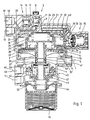
- the trailer control valve shown in FIG. 1 has a first control piston 2 in a housing 1, which can be controlled electrically and forms or divides a control chamber 4 on the upstream side with a partition 3 fixed to the housing.
- a brake chamber 5 is provided which is in permanent connection via a connection 6 to a brake line 7 leading to the trailer.
- a solenoid valve 8 is provided, at the inlet of which compressed air from a supply line 10 is constantly present via a line 9.
- the armature 11 of the solenoid valve 8 closes in the non-energized position, as shown, a passage valve for the supply air and opens a vent connection 12 to the atmosphere at its other end.
- a line 13 leads from the solenoid valve 8 to a second solenoid valve 14 without a vent connection.
- the armature 11 of the solenoid valve 14 is in the non-energized position shown in a position in which a shut-off valve between lines 13 and 16 is open.
- a holding function is realized in the excited position of the solenoid valve 14.
- the line 16 leads to the control chamber 4. It is thus possible to apply corresponding electrical signals to the solenoid valves 8 and 14 to the control chamber 4 of the control piston 2 accordingly with compressed air from the supply line 10.
- the solenoid valves 8 and 14 are acted upon by an electronic signal processing device, not shown here or controlled, the reason for such control being a desired braking operation.
- a second control piston 17 is sealingly and displaceably mounted in the housing 1 and is designed to be pneumatically controllable.
- a connection 18 for a pneumatic signal line 19 is provided on the housing 1, which leads via a connecting line 20 to a control chamber 21 above the control piston 17.
- the control piston 17 has in its central region a recess 22 in which a movement spring 23 is accommodated, which is supported on the one hand on the bottom of the recess 22 and on the other hand on a tied support 24.
- the support 24 is dimensioned and arranged such that it strikes the housing in the control chamber 21 and, on the other hand, there is still a distance between the control piston 17 and the upper housing wall.
- the partition wall 3 faces the second control piston 17 and matches an annular extension 25 on its recess 22, which carries a seal 26 which cooperates with a running surface 27 on the recess 22.
- a first reaction chamber 28 and a second reaction chamber 29 are divided on the side of the control piston 17 facing away from the control chamber 21 and the partition fixed to the housing.
- the control piston 17 thus has a first reaction surface 30 and a second reaction surface 31.
- the first reaction chamber 28 is in permanent communication with the brake chamber 5 via a line 32 and a connection line 33.
- the connection line 33 also leads to a pressure retention valve 34, which is provided on the outside of the housing 1 and forms an essential part of an otherwise known advance device.
- the pressure retention valve 34 has a valve body 35 which is biased by a spring and from which a line 36 leads on the outflow side to the second reaction chamber 29 and thus to the second reaction surface 31.
- the first control piston 2 has on its side facing the brake chamber 5 a hollow extension 37, the free edge 38 of which is assigned to a double valve body 40 and forms an outlet valve 38, 40 which is assigned to the control piston 2.
- the control piston 17 has an extension 39 which is sealingly passed through the partition 3 and ends at a free edge 41 which forms with the double valve body 40 a second outlet valve 41, 40 which is assigned to the control piston 17.
- the two free edges 38 and 41 are opposite one another.
- the extensions 37 and 39 are of equal length with respect to the double valve body 40, so that either the one or the other exhaust valve is closed when the control piston 2 or 17 is actuated selectively.
- the extensions 37 and 39 are thin-walled and designed so that the two free edges 38 and 41 differ only slightly in diameter.
- a seal 42 is provided to seal the extensions 37 and 39 against each other.
- the line 32 leads not only to the connecting line 33, but also to a pressure / voltage converter 43, with the aid of which the controlled brake pressure in the brake chamber 5 or the brake line 7 can thus be monitored.
- the pressure / voltage converter 43 is connected to a central signal processing device via an electrical line (not shown).
- control piston 44 which, as shown, can also consist of several parts, is mounted in a sliding and sealing manner.
- the control piston 44 is hollow and is used for the resilient suspension of the likewise hollow double valve body 40.
- the control piston 44 has an edge 45 on, which forms an inlet valve 40, 45 with the double valve body 40.
- the control piston 44 sealingly penetrates a housing wall 46 and forms a storage chamber 47 for compressed air in its interior following the double valve body 40.
- the supply chamber 47 is in permanent connection via a connection 48 to a supply line of a compressed air container or a compressed air supply device which is brought up to the trailer control valve.
- a control line 51 is connected to a connection 50 and has a connection to a hand brake valve in a known manner.
- the control circuit of a parking brake is controlled and in the release position, as shown, compressed air is sent to a space 52 and thus to the control piston 44, so that the control piston 44 assumes its lowest position, in which the inlet valve 40, 45 is closed and the Both exhaust valves are open so that the brake line 7 is connected to the atmosphere via the brake chamber 5 and through the hollow double valve body 40 and the hollow control piston 44 via a flap valve 53.
- the function of the trailer control valve according to Figure 1 is as follows: In contrast to known trailer control valves, which can also be controlled with two circuits, the control in the normal state takes place simultaneously via both control circuits. This is not the case with the trailer control valve according to the invention.
- the control piston 2 When the system is intact, only the electrical control is effective, ie only pressure is applied to the control piston 2 via the solenoid valves 8 and 14 for braking, while the control chamber 21 of the second control piston 17 is not pressurized with compressed air.
- the pneumatic actuation of the control piston 17 takes place only in an emergency or in the event of a defect, in order to ensure braking in this case too.
- the solenoid valve 8 is excited by an electrical signal, while the solenoid valve 14 remains unexcited.
- Compressed air thus passes from the supply line 10 as control air into the control chamber 4 and moves the control piston 2 downwards.
- the free edge 38 of the extension 37 rests on the double valve body 40, so that the outlet valve 38, 40 is closed and the inlet valve 40, 45 is subsequently opened.
- a lead which is also required for this normal actuation is provided in the electronic signal processing device.
- Compressed air passes from the supply line 49 into the brake chamber 5 and thus into the brake line 7 via the opened inlet valve 40, 45.
- the control piston 2 is acted upon in a reactive manner on its rear side.
- the solenoid valve 14 can be excited, for example, via the electronic device, so that a further build-up of pressure in the control chamber 4 is prevented. A final position is then set. Simultaneously with such a normal brake actuation, compressed air also comes from the brake chamber 5 via the line 32 and the connecting line 33 into the first reaction chamber 28 and acts on the reaction surface 30 of the control piston 17. Since the control chamber 21 is vented, this has the effect that the Control piston 17 works against the force of the movement spring 23, which is supported on the bearing 1 on the housing 1. The control piston 17 is thus also moved during normal actuation of only the control piston 2, so that it is functional in the event of a defect.
- the modulation of signals to the solenoid valves 8 and 14 is suppressed, so that the control chamber 4 is connected to the atmosphere via the vent connection 12 of the solenoid valve 8 and thus remains vented.
- compressed air is sent into the control chamber 21 via the signal line 19 and the control piston 17 is thus acted upon on the upstream side.
- the control piston 17 starts to move downward and its free edge 41 sits on the double valve body 40 while the outlet valve 40, 41 is closed.
- the inlet valve 40, 45 is opened again and normal braking, as it were, can be controlled for this emergency, but now the advance device 34, 35, 30, 31 is effective.
- the advance device does not necessarily have to be provided eccentrically on the housing 1. It can also be implemented in a central manner in the area of the control piston 17, as is known in the prior art.
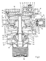
- the embodiment of the trailer control valve according to FIG. 2 is largely similar to the embodiment according to FIG. 1. Only the relative arrangement of the control pistons 2 and 17 is reversed, ie the pneumatically controllable control piston 17 is arranged closer to the double valve body 40, that is to say between the partition 3 and the double valve body 40, while the electrically controllable control piston 2 is provided above the partition 3.
- the partition 3 does not have an annular extension 25 here, but the seal 26 is provided on a second partition 54 fixed to the housing.
- the extension 39 encloses the extension 37 here, so that the radial position of the exhaust valves is reversed from one another.
- the pressure / voltage converter 43 is here via a line 55 the control chamber 4 connected so that the control-side pressure can be monitored.
- this trailer control valve otherwise corresponds to that of the exemplary embodiment in FIG. 1.
- the arrangement of partition walls 3 and 54 fixed to the housing is dispensed with.
- the two control pistons 2 and 17 are arranged nested one inside the other and can be accommodated as a unit in a housing 1 which is cylindrically recessed throughout.
- the control piston 2 enclosing the control piston 17 has three seals 56, 57, 58 on its outer diameter, the pneumatic actuation leading to the control chamber 21 via the signal line 19 between the two seals 56 and 57 and a bore 59.
- the line 36 leads from the pressure retention valve 34 into an annular space between the seals 57 and 58.
- a connection 60 connects to the second reaction chamber 29 and thus to the second reaction surface 31.
- a bore 61 in the relevant wall of the control piston 2 provides the permanent connection between the second reaction chamber 28 and the brake chamber 5.
Landscapes
- Engineering & Computer Science (AREA)
- Transportation (AREA)
- Mechanical Engineering (AREA)
- Physics & Mathematics (AREA)
- Fluid Mechanics (AREA)
- Braking Systems And Boosters (AREA)
- Valves And Accessory Devices For Braking Systems (AREA)
- Regulating Braking Force (AREA)
Description
- Die Erfindung bezieht sich auf ein Anhängersteuerventil für Kfz-Bremsanlagen, mit einem ersten Steuerkolben, der über ein elektrisch betätigbares Magnetventil ansteuerbar ist, und mit einem zweiten Steuerkolben, der pneumatisch ansteuerbar ist, wobei den beiden Steuerkolben ein Doppelventilkörper zugeordnet ist, der Bestandteil eines Einlaßventils und eines Auslaßventils ist. Solche zweikreisig ansteuerbaren Anhängersteuerventile sind bekannt. Sie dienen zum Erzeugen und Aussteuern eines Steuerdrucks in eine Bremsleitung, die zum Anhängefahrzeug führt.
- Ein Anhängersteuerventil der eingangs beschriebenen Art ist aus der DE 39 28 799 A1 bekannt. Beide Steuerkolben sind zunächst einmal über je einen Ansteuerkreis pneumatisch ansteuerbar. Der eine Steuerkolben ist zusätzlich zu seiner pneumatischen Ansteuerung über ein elektrisch betätigbares Magnetventil ansteuerbar, um damit den steuerdruck in der dem Steuerkolben zugeordneten Steuerkammer zusätzlich zu variieren. Das Magnetventil ist als Proportionalmagnetventil ausgebildet und wird aufgrund von Auswertsignalen geschaltet, die von einer Elektronik erstellt werden, an welche Sensoren angeschlossen sind, die zwischen Zugwagen und Anhängerfahrzeug angeordnet sind, um die Abbremsung der beiden Fahrzeugteile besser aufeinander abzustimmen. Die beiden Steuerkolben sind gegenläufig auf verschiedenen Seiten des Doppelventilkörpers vorgesehen. Nur der eine Steuerkolben ist mit einem einen Auslaßsitz für den Doppelventilkörper tragenden Fortsatz versehen, während der zusammen mit dem Doppelventilkörper das Einlaßventil bildende Rand Bestandteil eines Kolbens ist, der mit dem zweiten Steuerkolben in Wirkverbindung steht. Der erste Steuerkolben bildet auf seiner der Steuerkammer abgekehrten Rückseite eine Reaktionsfläche, die vom ausgesteuerten Steuerdruck in der Bremsleitung beaufschlagt wird. Der zweite Steuerkolben besitzt auf seiner Rückseite keine Reaktionsfläche, sondern ist hier von der Feststellbremse beaufschlagt, wobei zur Realisierung der Steuerkammer der Feststellbremse eine gehäusefeste Trennwand zwischen dem zweiten Steuerkolben und dem Doppelventilkörper vorgesehen ist. Das bekannte Anhängersteuerventil besitzt keine Voreileinrichtung. Bei Ausfall der elektrischen Ansteuerung über das Magnetventil erfolgt die Bremsung im Anhänger ohne Voreilung.
- Die DE-OS 19 58 808 zeigt ein über zwei Kreise pneumatisch ansteuerbares Anhängersteuerventil, bei dem die beiden Steuerkolben ebenfalls gegenläufig auf verschiedenen Seiten des Doppelventilkörpers angeordnet sind. Der Doppelventilkörper ist in einem der beiden Steuerkolben federnd aufgehängt, wobei die Vorratsluft unter den Einlaßsitz dieses Doppelventilkörpers geführt ist. Eine elektrische Ansteuermöglichkeit ist nicht vorgesehen. Auch verfügt das Anhängersteuerventil über keine Anschlußmöglichkeit für eine Feststellbremse. Die Rückseiten der beiden Steuerkolben sind als Reaktionsflächen ausgebildet und werden vom ausgesteuerten Druck in der Bremsleitung beaufschlagt. In einer besonderen Ausführungsform ist der Steuerkolben, der den Doppelventilkörper nicht trägt, mit einer Voreileinrichtung ausgestattet, wobei sich diese Voreilung in der Bremsleitung nur dann auswirkt, wenn die Ansteuerung über diesen einen Steuerkreis erfolgt. Bei einem Defekt dieses Steuerkreises und der Ansteuerung des Anhängersteuerventils durch den anderen Steuerkreis ist dann keine Voreilung vorhanden.
- Es sind jedoch auch über zwei Kreise pneumatisch ansteuerbare Anhängersteuerventile der anderen Bauart bekannt, bei der die beiden Steuerkolben gleichläufig benachbart auf der einen Seite des Doppelventilkörpers vorgesehen sind. Die DE 23 23 753 C3 zeigt ein solches Anhängersteuerventil. Nur der eine dem zweiten Steuerkreis zugeordnete Steuerkolben bildet auf seiner Rückseite eine Reaktionsfläche, die über eine Voreileinrichtung beaufschlagbar ist. Auch nur dieser zweite Steuerkolben besitzt einen Fortsatz, der einen Auslaßsitz trägt, der zusammen mit dem Doppelventilkörper das Auslaßventil bildet. Der erste Steuerkolben stützt sich an dem zweiten Steuerkolben direkt ab. Trotzdem wird damit der Vorteil erreicht, daS die Voreileinrichtung in beiden Kreisen wirksam wird; bei Ausfall eines Steuerkreises bleibt daher die Voreilfunktion erhalten. Der Doppelventilkörper bildet mit einem gehäusefesten Rand das Einlaßventil. Er ist darüberhinaus von einem Kolben umgeben, der auf seiner dem Doppelventilkörper abgewandten Vorderseite von der Feststellbremse beaufschlagt ist, während er auf seiner Rückseite eine Vorratskammer für Druckluft einer Druckluftquelle abschließt. Eine Ansteuerung über ein elektrisch betätigbares Magnetventil ist nicht vorgesehen. Der der Feststellbremse zugeordnete Kolben ist über eine zentrale Stange mit dem zweiten Steuerkolben verbunden. Eine Veränderung der Einstellung der Voreileinrichtung, z. B. zum Zwecke der Anpassung der Abstimmung der Abbremsung von Zug- und Anhängerfahrzeug, wirkt sich auch auf die Charakteristik der Feststellbremse aus.
- Die DE 35 42 175 A1 zeigt ebenfalls ein pneumatisch über zwei Kreise ansteuerbares Anhängersteuerventil mit den beiden Steuerkolben in gleichläufiger Bauart und benachbarter Anordnung auf einer Seite des Doppelventilkörpers. Auch hier stützt sich der eine Steuerkolben unmittelbar an dem anderen Steuerkolben ab. Der dem Doppelventilkörper zugekehrte Steuerkolben besitzt allein einen Fortsatz, der zusammen mit dem Doppelventilkörper das Auslaßventil bildet. In diesem Steuerkolben ist auch eine Voreileinrichtung untergebracht, über die ein gemeinsamer Reaktionsraum der beiden Steuerkolben beaufschlagbar ist. Die Voreilfunktion wirkt sich auf beide Kreise aus, d. h. auch bei Ausfall eines Kreises bleibt vorteilhaft die Voreilwirkung des Anhängersteuerventils vorhanden. Für die Feststellbremse ist ein gesonderter Kolben vorgesehen, in welchem auch der Doppelventilkörper aufgehängt ist, wobei ein Rand dieses Kolbens mit dem Doppelventilkörper ein bewegliches Einlaßventil bildet. Der Kolben ist von der Feststellbremse auf der dem Doppelventilkörper zugekehrten Seite beaufschlagt, so daß bei einer Betätigung der Feststellbremse der Doppelventilkörper auf dem Auslaßsitz des einen Steuerkolbens anschlägt und der am Kolben der Feststellbremse gebildete Rand sich dann von dem Doppelventilkörper unter Öffnung des Einlaßventils entfernt.
- Der Erfindung liegt die Aufgabe zugrunde, ein Anhängersteuerventil der eingangs beschriebenen Art bereitzustellen, welches also zumindest in einem Kreis über ein elektrisch betätigbares Magnetventil ansteuerbar ist und in einem zweiten Kreis insbesondere im Defektfall des ersten Kreises pneumatisch ansteuerbar ist und die beiden Ansteuerkreise ohne gegenseitige Beeinflussung am Anhängersteuerventil wirksam werden.
- Erfindungsgemäß wird dies bei dem Anhängersteuerventil der eingangs beschriebenen Art dadurch erreicht, daß die beiden Steuerkolben gleichläufig benachbart auf der einen Seite des Doppelventilkörpers vorgesehen und mit je einem je einen Auslaßsitz für den Doppelventilkörper tragenden Fortsatz versehen sind, daß an beiden Steuerkolben voneinander getrennte Reaktionsflächen vorgesehen sind, und daß nur der pneumatisch ansteuerbare Steuerkolben eine über eine Voreileinrichtung zugeordnete Reaktionsfläche aufweist.
- An sich ist die gleichläufige, benachbarte Anordnung der beiden Steuerkolben auf der einen Seite des Doppelventilkörpers im Stand der Technik bekannt. Mit dieser Bauart wird im Stand der Technik der Vorteil genutzt, daß sich die beiden Steuerkolben direkt aufeinander abstützen können und damit nur der eine Steuerkolben einen Fortsatz tragen muß, der Bestandteil des Auslaßventils ist. Auch eröffnet sich bekanntermaßen die vorteilhafte Möglichkeit der Anordnung einer Voreileinrichtung, die in beiden Kreisen wirksam wird. Die bekannte Bauart zielt damit in starkem Maß auf die Herstellung einer gegenseitigen Beeinflussung der beiden Steuerkreise ab und läuft damit der aufgabengemäß angesprochenen Problematik zuwider. Auch die doppelte Anordnung von Auslaßsitzen an jedem der beiden Steuerkolben erscheint bei gleichläufig benachbarter Anordnung der Steuerkolben zunächst widersinnig, eröffnet jedoch zur Lösung der vorliegenden Aufgabe die Möglichkeit, auch in diesem Bereich eine gegenseitige Beeinflussung der beiden Steuerkreise zu vermeiden, um bei Betätigung des einen Steuerkreises gleichsam ein erstes Auslaßventil und bei Betätigung des anderen Steuerkreises ein zweites Auslaßventil zu betätigen, und zwar unabhängig voneinander. Durch die Zwischenschaltung einer gehäusefesten Trennwand zwischen die beiden Steuerkolben oder auch in anderer Weise eröffnet sich die Möglichkeit, an beiden Steuerkolben voneinander getrennte und gegeneinander abgeschlossene Reaktionsflächen und Reaktionsräume zu schaffen, um nur an dem der pneumatischen Ansteuerung zugeordneten Steuerkolben die Voreileinrichtung zur Einwirkung zu bringen, dagegen im elektrisch ansteuerbaren Steuerkreis auf die Wirkung der Voreileinrichtung zu verzichten, um letztlich eine natürlich in diesem Kreis auch erforderliche Voreilung des ausgesteuerten Drucks mit anderen Mitteln zu verwirklichen, insbesondere durch eine im elektrischen Kreis dem Magnetventil und damit dem Anhängersteuerventil vorgeschaltete elektronische Signalverarbeitungseinrichtung. Es wird also über beide Steuerkreise je eine Voreilung erreicht. Die Voreilung über den elektrisch ansteuerbaren Kreis mit dem Magnetventil wird elektrisch erzeugt. Die Voreilung in dem pneumatisch ansteuerbaren Kreis wird in der bisher auch bekannten Weise über ein Druckrückhalteventil, ein Doppelrückschlagventil oder eine ähnliche Einrichtung verwirklicht. Wiederum beeinflussen sich die beiden Voreilungen nicht gegenseitig. Es besteht weiterhin die vorteilhafte Möglichkeit, den in die Anhängerbremsleitung ausgesteuerten steuerdruck des Anhängersteuerventils oder den Ansteuerdruck auf dem ersten Kolben zu messen, also z. B. mit einem Druck/Spannungsumwandler aufzunehmen und der elektronischen Steuereinrichtung zuzuführen, um letztlich eine Variation des in die Bremsleitung ausgesteuerten Drucks herbeizuführen.
- Das neue Anhängersteuerventil weist den weiteren Vorteil auf, daß im ordnungsgemäßen Zustand auch der pneumatisch ansteuerbare Steuerkolben, obwohl nicht angesteuert, dennoch bewegt wird, so daß seine Betriebssicherheit für den Defektfall aufrechterhalten wird. Diese Bewegung des nicht angesteuerten Steuerkolbens beeinflußt jedoch die Bewegung des angesteuerten Steuerkolbens in keiner Weise. Insbesondere beeinflussen sich die beiden Voreilungen nicht gegenseitig.
- Ein weiterer Vorteil des neuen Anhängersteuerventils liegt darin, daß es nur eine geringe Anzahl bewegter Teile aufweist und die bewegten Massen vergleichsweise gering sind, so daß sich eine große Feinfühligkeit in der Stufung des in die Bremsleitung ausgesteuerten Drucks ergibt.
- Besonders vorteilhaft ist es, wenn im Zusammenhang mit den beiden gegenläufig angeordneten Steuerkolben der Doppelventilkörper in einem dritten, der Feststellbremse zugeordneten Steuerkolben aufgehängt ist, der sich durch eine weitere gehäusefeste Trennwand hindurch erstreckt, die dem Doppelventilkörper zugekehrt eine Vorratskammer für Druckluft zum Einlaßventil und dem Doppelventilkörper abgekehrt eine Steuerkammer für den der Feststellbremse zugeordneten Steuerkolben abteilt. Damit ist der mit dem Doppelventilkörper das Einlaßventil bildende Rand nicht mehr gehäusefest angeordnet, sondern auf einem dritten Steuerkolben, der der Feststellbremse zugeordnet ist. Damit wird der Vorteil erreicht, daß sich nicht nur die beiden elektrisch und pneumatisch ansteuerbaren Steuerkolben der Betriebsbremse nicht gegenseitig beeinflussen, sondern die Feststellbremse beeinflußt zugleich keinen der beiden Steuerkreise der Betriebsbremse. Mit anderen Worten wird die Charakteristik der Feststellbremse auch dann nicht verändert, wenn die Voreilungen in den Steuerkreisen der Betriebsbremse zwecks Abstimmung der Abbremsung von Zug- und Anhängerfahrzeug verändert werden.
- In einer ersten vorteilhaften Ausführungsform ist der elektrisch ansteuerbare Steuerkolben zwischen der gehäusefesten Trennwand und dem Doppelventilkörper angeordnet und umschließt mit seinem Fortsatz den Fortsatz des pneumatisch ansteuerbaren Steuerkolbens, der die gehäusefeste Trennwand dichtend durchsetzt. Damit kann die Rückseite des elektrisch ansteuerbaren Steuerkolbens, die unmittelbar an die Bremskammer anschließt, ohne jeglichen Aufwand als Reaktionsfläche genutzt werden. Von dieser Bremskammer führt eine Leitung zur Rückseite des pneumatisch ansteuerbaren Kolbens, und zwar mit einem Abzweig direkt zu einer ersten Reaktionsfläche und über die Voreileinrichtung zu einer zweiten Reaktionsfläche.
- Der pneumatisch ansteuerbare Steuerkolben kann eine Vertiefung aufweisen, in der ansteuerseitig eine Bewegungsfeder untergebracht ist und die auf der anderen Seite eine Lauffläche für einen ringförmigen Fortsatz an der gehäusefesten Trennwand zur Abteilung von zwei Reaktionsflächen bildet. Damit wird die gehäusefeste Trennwand gleichzeitig zur Unterteilung der beiden an dem pneumatisch ansteuerbaren Steuerkolben erforderlichen Reaktionsflächen genutzt. Die Vertiefung dient aber auch zur Aufnahme der Bewegungsfeder, die vorzugsweise gefesselt an diesem Steuerkolben untergebracht ist und eine gehäuseseitige Abstützung ermöglicht. Damit wird der pneumatisch ansteuerbare Steuerkolben auch dann bewegt, wenn er nicht angesteuert wird, sondern lediglich der elektrisch ansteuerbare Steuerkolben, wie es bei intaktem Anhängersteuerventil und intakter Anlage der Fall ist. Durch diese besondere Anordnung wird eine geringe Bauhöhe erreicht. Dabei ist auch von Vorteil, daß das Druckhalteventil oder das Doppelrückschlagventil der Voreileinrichtung gleichsam radial außerhalb der Steuerkolben angeordnet ist.
- In einer weiteren Ausführungsform kann der pneumatisch ansteuerbare Steuerkolben auf der dem Doppelventilkörper zugekehrten Seite der gehäusefesten Trennwand angeordnet sein; dabei ist eine zweite gehäusefeste Trennwand zur Abteilung von zwei Reaktionsflächen an diesem Steuerkolben vorgesehen. Diese Bauart erbringt den Vorteil, daß die Leitungsanschlüsse für die beiden Ansteuerkreise gehäuseseitig leichter untergebracht werden können.
- Schließlich ist eine Bauart möglich, bei der der pneumatisch ansteuerbare Steuerkolben in dem elektrisch ansteuerbaren Steuerkolben angeordnet ist. Diese Bauart hat den Vorteil, daß eine gehäusefeste Trennwand in Fortfall kommt, so daß die beiden Steuerkolben eine besonders geringe Bauhöhe ergeben. Die beiden Steuerkolben können auch als leicht austauschbare Einheit im Defektfall schnell ausgewechselt werden.
- Dabei trägt der elektrisch ansteuerbare Steuerkolben an seinem Außendurchmesser drei Dichtungen, zwischen denen die Verbindungsleitungen für die Ansteuerung des pneumatisch ansteuerbaren Steuerkolbens und den über die Voreileinrichtung beaufschlagbaren Reaktionsraum vorgesehen sind.
- Bei allen Ausführungsformen sind die Fortsätze der beiden Steuerkolben zumindest im Bereich der Auslaßsitze dünnwandig ausgebildet und dichtend aneinander geführt. Dies bedeutet, daß die Fortsätze insbesondere an ihrem freien Ende einander eng umschließen, also nur geringfügig voneinander abweichende Durchmesser aufweisen, damit jeder Fortsatz mit dem Doppelventilkörper zusammenarbeiten und je ein Auslaßventil bilden kann, wobei beide Auslaßventile einem einzigen Einlaßventil zugeordnet sind. Im Bereich dieser Fortsätze ist eine Dichtung angeordnet, deren Reibung überwunden werden muß, wenn bestimmungsgemäß einer der beiden Steuerkolben betätigt wird. Dies ist aber die einzige, zwischen den beiden Steuerkolben wirkende und zu überwindende Kraft.
- Die Erfindung wird anhand bevorzugter Ausführungsbeispiele weiter beschrieben und erläutert. Es zeigen:
- Figur 1
- einen Vertikalschnitt durch eine erste Ausführungsform des Anhängersteuerventils,
- Figur 2
- einen Schnitt durch eine zweite Ausführungsform des Anhängersteuerventils und
- Figur 3
- einen Schnitt durch eine dritte Ausführungsform des Anhängersteuerventils.
- Das in Figur 1 dargestellte Anhängersteuerventil weist in einem Gehäuse 1 einen ersten Steuerkolben 2 auf, der elektrisch ansteuerbar ist und mit einer gehäusefesten Trennwand 3 anströmseitig eine Steuerkammer 4 bildet bzw. abteilt. Auf der anderen Seite des Steuerkolbens ist eine Bremskammer 5 vorgesehen, die über einen Anschluß 6 in dauernder Verbindung zu einer zum Anhänger führenden Bremsleitung 7 steht. Am Gehäuse 1 des Anhängersteuerventils ist in Zuordnung zu dem Steuerkolben 2 ein Magnetventil 8 vorgesehen, an dessen Einlaß über eine Leitung 9 ständig Druckluft aus einer Vorratsleitung 10 ansteht. Der Anker 11 des Magnetventils 8 schließt in der nicht-erregten Stellung, wie dargestellt, ein Durchlaßventil für die Vorratsluft ab und öffnet an seinem anderen Ende einen Entlüftungsanschluß 12 zur Atmosphäre. Von dem Magnetventil 8 führt eine Leitung 13 zu einem zweiten Magnetventil 14 ohne Entlüftungsanschluß. Der Anker 11 des Magnetventils 14 befindet sich in der nicht-erregten, dargestellten Stellung in einer Position, in der ein Absperrventil zwischen Leitungen 13 und 16 geöffnet ist. In der erregten Stellung des Magnetventils 14 wird eine Haltefunktion verwirklicht. Die Leitung 16 führt zur Steuerkammer 4. Damit ist es möglich, durch entsprechende elektrische Signale zu den Magnetventilen 8 und 14 die Steuerkammer 4 des Steuerkolbens 2 entsprechend mit Druckluft aus der Vorratsleitung 10 zu beaufschlagen. Die Magnetventile 8 und 14 werden von einer hier nicht dargestellten elektronischen Signalverarbeitungseinrichtung beaufschlagt bzw. gesteuert, wobei der Anlaß für eine solche Ansteuerung in einem gewünschten Bremsvorgang liegt.
- Oberhalb der Trennwand 3 ist im Gehäuse 1 ein zweiter Steuerkolben 17 dichtend und verschieblich gelagert, der pneumatisch ansteuerbar ausgebildet ist. Zu diesem Zweck ist am Gehäuse 1 ein Anschluß 18 für eine pneumatische Signalleitung 19 vorgesehen, die über eine Verbindungsleitung 20 zu einer Steuerkammer 21 oberhalb des Steuerkolbens 17 führt. Der Steuerkolben 17 besitzt in seinem Mittelbereich eine Vertiefung 22, in der eine Bewegungsfeder 23 untergebracht ist, die sich einerseits am Grund der Vertiefung 22 und andererseits auf einem gefesselt geführten Auflager 24 abstützt. Das Auflager 24 ist so bemessen und angeordnet, daß es in der Steuerkammer 21 am Gehäuse anschlägt und andererseits zwischen dem Steuerkolben 17 und der oberen Gehäusewand noch ein Abstand besteht. Die Trennwand 3 weist zugekehrt zu dem zweiten Steuerkolben 17 und abgestimmt auf dessen Vertiefung 22 einen ringförmigen Fortsatz 25 auf, der eine Dichtung 26 trägt, die mit einer Lauffläche 27 an der Vertiefung 22 zusammenarbeitet. Damit wird auf der der Steuerkammer 21 abgekehrten Seite des Steuerkolbens 17 und der gehäusefesten Trennwand ein erster Reaktionsraum 28 und ein zweiter Reaktionsraum 29 abgeteilt. In Zuordnung besitzt somit der Steuerkolben 17 eine erste Reaktionsfläche 30 und eine zweite Reaktionsfläche 31. Der erste Reaktionsraum 28 steht über eine Leitung 32 und eine Verbindungsleitung 33 in dauernder Verbindung zu der Bremskammer 5. Andererseits führt die Verbindungsleitung 33 auch zu einem Druckrückhalteventil 34, welches außen am Gehäuse 1 vorgesehen ist und einen wesentlichen Bestandteil einer ansonsten bekannten Voreileinrichtung bildet. Das Druckrückhalteventil 34 besitzt einen über eine Feder vorgespannten Ventilkörper 35, von dem abströmseitig eine Leitung 36 zu dem zweiten Reaktionsraum 29 und damit zur zweiten Reaktionsfläche 31 führt.
- Der erste Steuerkolben 2 besitzt auf seiner der Bremskammer 5 zugekehrten Seite einen hohlen Fortsatz 37, dessen freier Rand 38 einem Doppelventilkörper 40 zugeordnet ist und mit diesem ein Auslaßventil 38, 40 bildet, welches dem Steuerkolben 2 zugeordnet ist. Aber auch der Steuerkolben 17 besitzt einen Fortsatz 39, der durch die Trennwand 3 dichtend hindurchgeführt ist und an einem freien Rand 41 endet, der mit dem Doppelventilkörper 40 ein zweites Auslaßventil 41, 40 bildet, welches dem Steuerkolben 17 zugeordnet ist. In der nicht beaufschlagten Ausgangsstellung liegen sich die beiden freien Ränder 38 und 41 gegenüber, d. h. die Fortsätze 37 und 39 sind gleich lang gegenüber dem Doppelventilkörper 40 ausgebildet, so daß bei einer wahlweisen Betätigung der Steuerkolben 2 oder 17 entweder das eine oder andere Auslaßventil geschlossen wird. Die Fortsätze 37 und 39 sind dünnwandig ausgebildet und so gestaltet, daß die beiden freien Ränder 38 und 41 im Durchmesser nur geringfügig voneinander abweichen. Außerdem ist eine Dichtung 42 vorgesehen, um die Fortsätze 37 und 39 gegeneinander abzudichten.
- Die Leitung 32 führt nicht nur zu der Verbindungsleitung 33, sondern auch noch zu einem Druck/Spannungswandler 43, mit dessen Hilfe somit der ausgesteuerte Bremsdruck in der Bremskammer 5 bzw. der Bremsleitung 7 überwacht werden kann. Der Druck/Spannungswandler 43 ist über eine nicht dargestellte elektrische Leitung mit einer zentralen Signalverarbeitungseinrichtung verbunden.
- Im unteren Bereich des Gehäuses 1 ist ein dritter Steuerkolben 44, der, wie dargestellt, auch aus mehreren Teilen bestehen kann, gleitend und dichtend gelagert. Der Steuerkolben 44 ist hohl ausgebildet und dient zur federnden Aufhängung des ebenfalls hohl ausgebildeten Doppelventilkörpers 40. Der Steuerkolben 44 weist einen Rand 45 auf, der mit dem Doppelventilkörper 40 ein Einlaßventil 40, 45 bildet. Der Steuerkolben 44 durchsetzt dichtend eine Gehäusewand 46 und bildet in seinem Innern im Anschluß an den Doppelventilkörper 40 eine Vorratskammer 47 für Druckluft. Die Vorratskammer 47 steht über einen Anschluß 48 in dauernder Verbindung zu einer zum Anhängersteuerventil herangeführten Vorratsleitung eines Druckluftbehälters bzw. einer Druckluftbeschaffungseinrichtung. An einem Anschluß 50 ist eine Steuerleitung 51 angeschlossen, die in bekannter Weise Verbindung zu einem Handbremsventil hat. Über dieses Handbremsventil wird der Steuerkreis einer Feststellbremse ausgesteuert und in der Lösestellung, wie dargestellt, Druckluft in einen Raum 52 und damit auf den Steuerkolben 44 geschickt, so daß der Steuerkolben 44 seine unterste Stellung einnimmt, in der das Einlaßventil 40, 45 geschlossen und die beiden Auslaßventile geöffnet sind, so daß die Bremsleitung 7 über die Bremskammer 5 und durch den hohlen Doppelventilkörper 40 und den hohlen Steuerkolben 44 über ein Flatterventil 53 an die Atmosphäre angeschlossen ist.
- Die Funktion des Anhängersteuerventil gemäß Figur 1 ist folgende:
Im Gegensatz zu bekannten Anhängersteuerventilen, die zwar auch zweikreisig ansteuerbar sind, erfolgt dort die Ansteuerung im Normalzustand gleichzeitig über beide Ansteuerkreise. Bei dem erfindungsgemäßen Anhängersteuerventil ist die nicht der Fall. Hier ist bei intakter Anlage nur die elektrische Ansteuerung wirksam, d. h. über die Magnetventile 8 und 14 wird für eine Bremsung nur Druck auf den Steuerkolben 2 geschickt, während die Steuerkammer 21 des zweiten Steuerkolbens 17 nicht mit Druckluft beaufschlagt wird. Lediglich im Notfall bzw. Defektfall erfolgt die pneumatische Ansteuerung des Steuerkolbens 17 (allein), um auch in diesem Fall eine Bremsung zu gewährleisten. - Im Normalfall, d. h. bei intakter Anlage, wird durch ein elektrisches Signal das Magnetventil 8 erregt, während das Magnetventil 14 unerregt bleibt. Damit gelangt Druckluft aus der Vorratsleitung 10 als Steuerluft in die Steuerkammer 4 und verschiebt den Steuerkolben 2 nach unten. Der freie Rand 38 des Fortsatzes 37 setzt auf dem Doppelventilkörper 40 auf, so daß das Auslaßventil 38, 40 geschlossen und nachfolgend das Einlaßventil 40, 45 geöffnet wird. Eine bei dieser Normalbetätigung ebenfalls erforderliche Voreilung wird in der elektronischen Signalverarbeitungseinrichtung bereitgestellt. Über das geöffnete Einlaßventil 40, 45 gelangt Druckluft aus der Vorratsleitung 49 in die Bremskammer 5 und damit in die Bremsleitung 7. Der Steuerkolben 2 wird auf seiner Rückseite reaktionsmäßig beaufschlagt. Ist der ausgesteuerte Bremsdruck ausreichend, dann kann beispielsweise über die elektronische Einrichtung das Magnetventil 14 erregt werden, so daß ein weiterer Druckaufbau in der Steuerkammer 4 verhindert wird. Es stellt sich in der Folge eine Abschlußstellung ein. Gleichzeitig mit einer solchen normalen Bremsbetätigung gelangt auch Druckluft aus der Bremskammer 5 über die Leitung 32 und die Verbindungsleitung 33 in den ersten Reaktionsraum 28 und beaufschlagt die Reaktionsfläche 30 des Steuerkolbens 17. Da die Steuerkammer 21 entlüftet ist, wirkt sich dies so aus, daß der Steuerkolben 17 gegen die Kraft der Bewegungsfeder 23 arbeitet, die sich über das Auflager 24 am Gehäuse 1 abstützt. Der Steuerkolben 17 wird damit auch bei einer normalen Betätigung nur des Steuerkolbens 2 mit bewegt, so daß er im Defektfall funktionstüchtig zur Verfügung steht. Ob bei einer solchen Normalbetätigung je nach der Höhe des ausgesteuerten Bremsdrucks das Druckrückhalteventil 34 anspricht oder nicht, ist letztlich ohne Belang. Ggf. wird auch der zweite Reaktionsraum 29 und damit die zweite Reaktionsfläche 31 beaufschlagt, was sich aber auch nur in einer Bewegung des zweiten Steuerkolbens 17 äußert.
- Liegt ein Defekt im Bereich des elektrisch ansteuerbaren Steuerkolbens 2 und/oder im Bereich der elektronischen Signalverarbeitungseinrichtung vor, dann wird die Aussteuerung von Signalen zu den Magnetventilen 8 und 14 unterdrückt, so daß die Steuerkammer 4 über den Entlüftungsanschluß 12 des Magnetventils 8 an die Atmosphäre angeschlossen und damit entlüftet bleibt. In diesem Fall wird über die Signalleitung 19 Druckluft in die Steuerkammer 21 geschickt und damit der Steuerkolben 17 anströmseitig beaufschlagt. Der Steuerkolben 17 setzt sich nach unten in Bewegung und sein freier Rand 41 setzt sich unter Schließen des Auslaßventils 40, 41 auf dem Doppelventilkörper 40 auf. In der Folge wird wiederum das Einlaßventil 40, 45 geöffnet und es kann für diesen Notfall eine gleichsam normale Bremsung ausgesteuert werden, wobei jedoch jetzt die Voreileinrichtung 34, 35, 30, 31 wirksam wird. Die Voreileinrichtung muß nicht unbedingt exzentrisch am Gehäuse 1 vorgesehen sein. Sie kann auch in zentrischer Weise im Bereich des Steuerkolbens 17 verwirklicht werden, wie dies im Stand der Technik bekannt ist.
- Die Ausführungsform des Anhängersteuerventils gemäß Figur 2 ist in weiten Bereichen ähnlich der Ausführungsform gemäß Figur 1 gestaltet. Lediglich die relative Anordnung der Steuerkolben 2 und 17 ist umgekehrt, d. h. der pneumatisch ansteuerbare Steuerkolben 17 ist hier näher zum Doppelventilkörper 40, also zwischen der Trennwand 3 und dem Doppelventilkörper 40 angeordnet, während der elektrisch ansteuerbare Steuerkolben 2 oberhalb der Trennwand 3 vorgesehen ist. Die Trennwand 3 besitzt hier keinen ringförmigen Fortsatz 25, sondern die Dichtung 26 ist an einer zweiten gehäusefesten Trennwand 54 vorgesehen. Der Fortsatz 39 umschließt hier den Fortsatz 37, so daß die radiale Lage der Auslaßventile zueinander umgekehrt ist. Der Druck/Spannungswandler 43 ist hier über eine Leitung 55 an die Steuerkammer 4 angeschlossen, so daß insoweit der ansteuerseitige Druck überwacht werden kann.
- Die Funktion dieses Anhängersteuerventils entspricht ansonsten der des Ausführungsbeispiels der Figur 1.
- Bei der Ausführungsform gemäß Figur 3 ist auf die Anordnung von gehäusefesten Trennwänden 3 bzw. 54 verzichtet. Die beiden Steuerkolben 2 und 17 sind ineinandergeschachtelt angeordnet und können als Einheit in einem durchgehend zylindrisch ausgenommenen Gehäuse 1 untergebracht sein. Der den Steuerkolben 17 umschließende Steuerkolben 2 besitzt auf seinem äußeren Durchmesser drei Dichtungen 56, 57, 58, wobei die pneumatische Ansteuerung über die Signalleitung 19 zwischen den beiden Dichtungen 56 und 57 und eine Bohrung 59 zu der Steuerkammer 21 führt. Vom Druckrückhalteventil 34 führt die Leitung 36 in einen Ringraum zwischen den Dichtungen 57 und 58. Über einen Kanal 60 besteht Anschluß an den zweiten Reaktionsraum 29 und damit auf die zweite Reaktionsfläche 31. Eine Bohrung 61 in der betreffenden Wand des Steuerkolbens 2 stellt die dauernde Verbindung zwischen dem zweiten Reaktionsraum 28 und der Bremskammer 5 her.
- Auch mit diesem Anhängersteuerventil wird die Funktion erreicht, die anhand der Ausführungsbeispiele der Figuren 1 und 2 bereits beschrieben ist.
-
- 1
- = Gehäuse
- 2
- = Steuerkolben
- 3
- = Trennwand
- 4
- = Steuerkammer
- 5
- = Bremskammer
- 6
- = Anschluß
- 7
- = Bremsleitung
- 8
- = Magnetventil
- 9
- = Leitung
- 10
- = Vorratsleitung
- 11
- = Anker
- 12
- = Entlüftungsanschluß
- 13
- = Leitung
- 14
- = Magnetventil
- 15
- = Anker
- 16
- = Leitung
- 17
- = Steuerkolben
- 18
- = Anschluß
- 19
- = Signalleitung
- 20
- = Verbindungsleitung
- 21
- = Steuerkammer
- 22
- = Vertiefung
- 23
- = Bewegungsfeder
- 24
- = Auflager
- 25
- = Fortsatz
- 26
- = Dichtung
- 27
- = Lauffläche
- 28
- = Reaktionsraum
- 29
- = Reaktionsraum
- 30
- = Reaktionsfläche
- 30'
- = Reaktionsfläche
- 31
- = Reaktionsfläche
- 32
- = Leitung
- 33
- = Verbindungsleitung
- 34
- = Druckrückhalteventil
- 35
- = Ventilkörper
- 36
- = Leitung
- 37
- = Fortsatz
- 38
- = Rand
- 39
- = Fortsatz
- 40
- = Doppelventilkörper
- 41
- = Rand
- 42
- = Dichtung
- 43
- = Druck/Spannungswandler
- 44
- = Steuerkolben
- 45
- = Rand
- 46
- = Gehäusewand
- 47
- = Vorratskammer
- 48
- = Anschluß
- 49
- = Vorratsleitung
- 50
- = Anschluß
- 51
- = Leitung
- 52
- = Raum
- 53
- = Flatterventil
- 54
- = Trennwand
- 55
- = Leitung
- 56
- = Dichtung
- 57
- = Dichtung
- 58
- = Dichtung
- 59
- = Bohrung
- 60
- = Kanal
- 61
- = Bohrung
Claims (9)
- Anhängersteuerventil für Kfz-Bremsanlagen, mit einem ersten Steuerkolben (2), der über ein elektrisch betätigbares Magnetventil (8) ansteuerbar ist, und mit einem zweiten Steuerkolben (17), der pneumatisch ansteuerbar ist, wobei den beiden Steuerkolben (2, 17) ein Doppelventilkörper (40) zugeordnet ist, der Bestandteil eines Einlaßventils (40, 45) und eines Auslaßventils ist, dadurch gekennzeichnet, daß die beiden Steuerkolben (2, 17) gleichläufig benachbart auf der einen Seite des Doppelventilkörpers (40) vorgesehen und mit je einem je einen Auslaßsitz (38, 40; 41, 40) für den Doppelventilkörper (40) tragenden Fortsatz (37, 39) versehen sind, daß an beiden Steuerkolben (2, 17) voneinander getrennte Reaktionsflächen (30'; 30, 31) vorgesehen sind, und daß nur der pneumatisch ansteuerbare Steuerkolben (17) eine über eine Voreileinrichtung (34, 35, 30, 31) beaufschlagbare zugeordnete Reaktionsfläche (31) aufweist.
- Anhängersteuerventil nach Anspruch 1, dadurch gekennzeichnet, daß zwischen den beiden Steuerkolben (2, 17) eine gehäusefeste Trennwand (3) vorgesehen ist, die bezüglich des einen Steuerkolbens (17) mehrere Reaktionsräume (28, 29) und bezüglich des anderen Steuerkolbens (2) eine Steuerkammer (4) abteilt.
- Anhängersteuerventil nach Anspruch 1 oder 2, dadurch gekennzeichnet, daß der Doppelventilkörper (40) in einem dritten, der Feststellbremse zugeordneten Steuerkolben (44) aufgehängt ist, der sich durch eine weitere gehäusefeste Trennwand (46) hindurch erstreckt, die dem Doppelventilkörper (40) zugekehrt eine Vorratskammer (47) für Druckluft zum Einlaßventil (40, 45) und dem Doppelventilkörper (40) abgekehrt eine Steuerkammer (52) für den der Feststellbremse zugeordneten Steuerkolben (44) abteilt.
- Anhängersteuerventil nach Anspruch 1 und 2, dadurch gekennzeichnet, daß der elektrisch ansteuerbare Steuerkolben (2) zwischen der gehäusefesten Trennwand (3) und dem Doppelventilkörper (40) angeordnet ist und mit seinem Fortsatz (37) den Fortsatz (39) des pneumatisch ansteuerbaren Steuerkolbens (17), der die gehäusefeste Trennwand (3) dichtend durchsetzt, umschließt.
- Anhängersteuerventil nach Anspruch 4, dadurch gekennzeichnet, daß der pneumatisch ansteuerbare Steuerkolben (17) eine Vertiefung (22) aufweist, in der ansteuerseitig eine Bewegungsfeder (23) untergebracht ist und die auf der anderen Seite eine Lauffläche (27) für einen ringförmigen Fortsatz (25) an der gehäusefesten Trennwand (3) zur Abteilung von zwei Reaktionsflächen (30, 31) bildet.
- Anhängersteuerventil nach Anspruch 1 und 2, dadurch gekennzeichnet, daS der pneumatisch ansteuerbare Steuerkolben (17) auf der dem Doppelventilkörper (40) zugekehrten Seite der gehäusefesten Trennwand (3) angeordnet ist, und daß eine zweite gehäusefeste Trennwand (54) zur Abteilung von zwei Reaktionsflächen (30, 31) an diesem Steuerkolben vorgesehen ist.
- Anhängersteuerventil nach Anspruch 1, dadurch gekennzeichnet, daß der pneumatisch ansteuerbare Steuerkolben (17) in dem elektrisch ansteuerbaren Steuerkolben (2) angeordnet ist.
- Anhängersteuerventil nach Anspruch 7, dadurch gekennzeichnet, daß der elektrisch ansteuerbare Steuerkolben (2) auf seinem Außendurchmesser drei Dichtungen (56, 57, 58) trägt, zwischen denen die Verbindungsleitungen für die Ansteuerung des pneumatisch ansteuerbare Steuerkolbens (17) und den über die Voreileinrichtung (34, 35, 30, 31) beaufschlagbaren Reaktionsraum (29) vorgesehen sind.
- Anhängersteuerventil nach Anspruch 1, dadurch gekennzeichnet, daß die Fortsätze (37, 39) der beiden Steuerkolben (2, 17) zumindest im Bereich der Auslaßsitze (38, 40; 41, 40) dünnwandig ausgebildet sind und dichtend aneinander geführt sind.
Applications Claiming Priority (2)
| Application Number | Priority Date | Filing Date | Title |
|---|---|---|---|
| DE4226697 | 1992-08-12 | ||
| DE19924226697 DE4226697C1 (de) | 1992-08-12 | 1992-08-12 |
Publications (2)
| Publication Number | Publication Date |
|---|---|
| EP0582990A1 EP0582990A1 (de) | 1994-02-16 |
| EP0582990B1 true EP0582990B1 (de) | 1995-10-18 |
Family
ID=6465400
Family Applications (1)
| Application Number | Title | Priority Date | Filing Date |
|---|---|---|---|
| EP19930112747 Expired - Lifetime EP0582990B1 (de) | 1992-08-12 | 1993-08-09 | Anhängersteuerventil für Kfz-Bremsanlagen |
Country Status (2)
| Country | Link |
|---|---|
| EP (1) | EP0582990B1 (de) |
| DE (1) | DE4226697C1 (de) |
Families Citing this family (13)
| Publication number | Priority date | Publication date | Assignee | Title |
|---|---|---|---|---|
| DE19609222A1 (de) * | 1996-03-09 | 1997-09-11 | Bosch Gmbh Robert | Anhängersteuerventil für eine Druckluftbremsanlage für Kraftfahrzeuge |
| DE19902225A1 (de) * | 1999-01-21 | 2000-07-27 | Knorr Bremse Systeme | Anhängersteuerventil für eine Druckluftbremsanlage von Zugfahrzeug-Anhänger-Kombinationen |
| DE10130541A1 (de) * | 2001-06-25 | 2003-01-09 | Knorr Bremse Systeme | Kombinierte elektro-pneumatisch und mechanisch betätigbare Ventileinrichtung und Steuervorrichtung für ein Bremssystem |
| DE10236920B4 (de) * | 2002-08-12 | 2005-09-29 | Knorr-Bremse Systeme für Nutzfahrzeuge GmbH | Elektronisches Bremssystem, insbesondere für Nutzfahrzeuganhänger |
| DE10238182A1 (de) * | 2002-08-21 | 2004-03-04 | Wabco Gmbh & Co. Ohg | Proportional-Relaisventil |
| EP1518773B1 (de) * | 2003-09-24 | 2008-02-06 | WABCO GmbH | Anhängersteuerventil für Zugfahrzeug mit elektronisch geregelter Bremsanlage |
| DE102009032313A1 (de) * | 2009-07-09 | 2011-01-13 | Wabco Gmbh | Anhängersteuerventil für eine Druckluftbremsanlage |
| DE102009057890B4 (de) * | 2009-12-11 | 2012-02-02 | Knorr-Bremse Systeme für Nutzfahrzeuge GmbH | Anhängersteuermodul zur Bremssteuerung eines Anhängers und Verfahren zum Betreiben des Anhängersteuermoduls |
| DE102014009179A1 (de) * | 2014-06-21 | 2015-12-24 | Wabco Gmbh | Ventilanordnung |
| DE102015112490B4 (de) | 2015-07-30 | 2018-07-19 | Knorr-Bremse Systeme für Nutzfahrzeuge GmbH | Elektro-pneumatische Steuereinrichtung einer elektro-pneumatischen Bremsanlage einer Zugfahrzeug-Anhängerkombination |
| DE102017010136A1 (de) * | 2017-10-28 | 2019-05-02 | Wabco Gmbh | Ventil und pneumatische Bremsanlage |
| CN108146414B (zh) * | 2018-01-05 | 2023-06-27 | 温州瑞立科密汽车电子有限公司 | 一种有比例输出的电子驻车阀及控制方法 |
| DE102018121721A1 (de) | 2018-09-06 | 2020-03-12 | Knorr-Bremse Systeme für Nutzfahrzeuge GmbH | Gehäuse für einen elektropneumatischen Modulator für eine elektropneumatische Bremsanlage für ein Fahrzeug, elektropneumatischer Modulator mit einem Gehäuse und Verfahren zum Herstellen eines elektropneumatischen Modulators |
Family Cites Families (7)
| Publication number | Priority date | Publication date | Assignee | Title |
|---|---|---|---|---|
| DE1958808B2 (de) * | 1969-11-22 | 1973-11-29 | Westinghouse Bremsen- Und Apparatebau Gmbh, 3000 Hannover | Relaisventil zur Verwendung als Anhängerbremsventil fur Zweikreis Druckluftbremsanlagen von Straßen fahrzeugen |
| DE2323753C3 (de) * | 1973-05-11 | 1975-11-20 | Graubremse Gmbh, 6900 Heidelberg | Über zwei Kreise ansteuerbares Anhängersteuerventil, insbesondere für Druckluftbremsanlagen an Kraftfahrzeugen |
| DE3542175A1 (de) * | 1985-11-29 | 1987-06-04 | Wabco Westinghouse Fahrzeug | Zweikreisig ansteuerbares bremsdruck-steuerventil |
| DE3731979A1 (de) * | 1987-09-23 | 1989-04-13 | Wabco Westinghouse Fahrzeug | Zweikreisig ansteuerbares bremsdruck-steuerventil |
| GB8817796D0 (en) * | 1988-07-26 | 1988-09-01 | Bendix Ltd | Fluid pressure control relay valve device & apparatus |
| DE3901269A1 (de) * | 1989-01-18 | 1990-07-19 | Bosch Gmbh Robert | Druckluftbremseinrichtung fuer kraftfahrzeuge |
| DE3928799C2 (de) * | 1989-08-31 | 1998-06-04 | Bosch Gmbh Robert | Anhänger-Steuerventil |
-
1992
- 1992-08-12 DE DE19924226697 patent/DE4226697C1/de not_active Expired - Fee Related
-
1993
- 1993-08-09 EP EP19930112747 patent/EP0582990B1/de not_active Expired - Lifetime
Also Published As
| Publication number | Publication date |
|---|---|
| EP0582990A1 (de) | 1994-02-16 |
| DE4226697C1 (de) | 1993-09-23 |
Similar Documents
| Publication | Publication Date | Title |
|---|---|---|
| DE3920766C2 (de) | Unterdruckbremskraftverstärker für eine schlupfgeregelte Bremsanlage | |
| DE2036220A1 (de) | Einrichtung zum Verhindern des Schleuderns bei Fahrzeugen | |
| EP0582990B1 (de) | Anhängersteuerventil für Kfz-Bremsanlagen | |
| EP0726190B1 (de) | Druckmittelbetätigte Fahrzeugbremsanlage | |
| DE1907131B2 (de) | Fahrzeugbremsanlage | |
| DE2448510B2 (de) | Relaisventil für eine blockiergeschützte Fahrzeug-Druckluftbremsanlage | |
| DE1555528C3 (de) | Bremsdruckverteiler für hydraulische Faftrzeug-Bremsanfagen | |
| EP0726189B1 (de) | Druckmittelbetätigte Fahrzeugbremsanlage | |
| DE19510492A1 (de) | Relaisventileinrichtung | |
| DE2421915C3 (de) | Relaisventil für eine blockiergeschützte Fahrzeug-Druckluftbremsanlage | |
| DE2333637A1 (de) | Bremsvorrichtung | |
| DE2138168B2 (de) | Blockiergeschuetzte druckluftbremsanlage fuer fahrzeuge | |
| DE3809338C1 (en) | Control valve with relay action for motor vehicles or trailers | |
| DE4226714A1 (de) | Bremssteuervorrichtung | |
| DE2263422C2 (de) | Relaisventil für eine blockiergeschützte Fahrzeugbremse | |
| DE2744407A1 (de) | Bremsdrucksteuereinheit fuer hydraulische fahrzeugbremsanlagen | |
| DE3922566C2 (de) | ||
| DE3519182C2 (de) | ||
| EP0439729B1 (de) | Elektronisch geregelte Druckluftbremsanlage für Fahrzeuge, insbesondere Nutzfahrzeuge | |
| DE3439086A1 (de) | Relaisventileinrichtung | |
| EP0070407A1 (de) | Zweikreis-Bremsventil für Kraftfahrzeuge | |
| DE2022073A1 (de) | Fahrzeug-Bremssystem | |
| EP0169303A2 (de) | Anhänger-Steuerventil | |
| DE4438154A1 (de) | Umschaltventil für mehrkreisige Bremsanlagen von Kraftfahrzeugen | |
| EP0026346B1 (de) | Mechanisch betätigbares Bremsventil, insbesondere Fussbremsventil für Zweikreis-Bremsanlagen von Fahrzeugen |
Legal Events
| Date | Code | Title | Description |
|---|---|---|---|
| PUAI | Public reference made under article 153(3) epc to a published international application that has entered the european phase |
Free format text: ORIGINAL CODE: 0009012 |
|
| AK | Designated contracting states |
Kind code of ref document: A1 Designated state(s): FR GB IT |
|
| 17P | Request for examination filed |
Effective date: 19940204 |
|
| 17Q | First examination report despatched |
Effective date: 19950125 |
|
| ITF | It: translation for a ep patent filed |
Owner name: DE DOMINICIS & MAYER S.R.L. |
|
| GRAA | (expected) grant |
Free format text: ORIGINAL CODE: 0009210 |
|
| AK | Designated contracting states |
Kind code of ref document: B1 Designated state(s): FR GB IT |
|
| GBT | Gb: translation of ep patent filed (gb section 77(6)(a)/1977) |
Effective date: 19951024 |
|
| ET | Fr: translation filed | ||
| PLBE | No opposition filed within time limit |
Free format text: ORIGINAL CODE: 0009261 |
|
| STAA | Information on the status of an ep patent application or granted ep patent |
Free format text: STATUS: NO OPPOSITION FILED WITHIN TIME LIMIT |
|
| 26N | No opposition filed | ||
| REG | Reference to a national code |
Ref country code: GB Ref legal event code: IF02 |
|
| REG | Reference to a national code |
Ref country code: FR Ref legal event code: TP Ref country code: FR Ref legal event code: CD |
|
| PGFP | Annual fee paid to national office [announced via postgrant information from national office to epo] |
Ref country code: GB Payment date: 20020726 Year of fee payment: 10 |
|
| PGFP | Annual fee paid to national office [announced via postgrant information from national office to epo] |
Ref country code: FR Payment date: 20020819 Year of fee payment: 10 |
|
| REG | Reference to a national code |
Ref country code: GB Ref legal event code: 732E |
|
| PG25 | Lapsed in a contracting state [announced via postgrant information from national office to epo] |
Ref country code: GB Free format text: LAPSE BECAUSE OF NON-PAYMENT OF DUE FEES Effective date: 20030809 |
|
| GBPC | Gb: european patent ceased through non-payment of renewal fee |
Effective date: 20030809 |
|
| PG25 | Lapsed in a contracting state [announced via postgrant information from national office to epo] |
Ref country code: FR Free format text: LAPSE BECAUSE OF NON-PAYMENT OF DUE FEES Effective date: 20040430 |
|
| REG | Reference to a national code |
Ref country code: FR Ref legal event code: ST |
|
| PG25 | Lapsed in a contracting state [announced via postgrant information from national office to epo] |
Ref country code: IT Free format text: LAPSE BECAUSE OF NON-PAYMENT OF DUE FEES;WARNING: LAPSES OF ITALIAN PATENTS WITH EFFECTIVE DATE BEFORE 2007 MAY HAVE OCCURRED AT ANY TIME BEFORE 2007. THE CORRECT EFFECTIVE DATE MAY BE DIFFERENT FROM THE ONE RECORDED. Effective date: 20050809 |