EP0582467B1 - Motorsteuerung - Google Patents
Motorsteuerung Download PDFInfo
- Publication number
- EP0582467B1 EP0582467B1 EP93306151A EP93306151A EP0582467B1 EP 0582467 B1 EP0582467 B1 EP 0582467B1 EP 93306151 A EP93306151 A EP 93306151A EP 93306151 A EP93306151 A EP 93306151A EP 0582467 B1 EP0582467 B1 EP 0582467B1
- Authority
- EP
- European Patent Office
- Prior art keywords
- auxiliary
- main
- series
- power supply
- excitation
- Prior art date
- Legal status (The legal status is an assumption and is not a legal conclusion. Google has not performed a legal analysis and makes no representation as to the accuracy of the status listed.)
- Expired - Lifetime
Links
Images
Classifications
-
- H—ELECTRICITY
- H02—GENERATION; CONVERSION OR DISTRIBUTION OF ELECTRIC POWER
- H02P—CONTROL OR REGULATION OF ELECTRIC MOTORS, ELECTRIC GENERATORS OR DYNAMO-ELECTRIC CONVERTERS; CONTROLLING TRANSFORMERS, REACTORS OR CHOKE COILS
- H02P7/00—Arrangements for regulating or controlling the speed or torque of electric DC motors
- H02P7/06—Arrangements for regulating or controlling the speed or torque of electric DC motors for regulating or controlling an individual DC dynamo-electric motor by varying field or armature current
- H02P7/18—Arrangements for regulating or controlling the speed or torque of electric DC motors for regulating or controlling an individual DC dynamo-electric motor by varying field or armature current by master control with auxiliary power
- H02P7/24—Arrangements for regulating or controlling the speed or torque of electric DC motors for regulating or controlling an individual DC dynamo-electric motor by varying field or armature current by master control with auxiliary power using discharge tubes or semiconductor devices
- H02P7/28—Arrangements for regulating or controlling the speed or torque of electric DC motors for regulating or controlling an individual DC dynamo-electric motor by varying field or armature current by master control with auxiliary power using discharge tubes or semiconductor devices using semiconductor devices
- H02P7/298—Arrangements for regulating or controlling the speed or torque of electric DC motors for regulating or controlling an individual DC dynamo-electric motor by varying field or armature current by master control with auxiliary power using discharge tubes or semiconductor devices using semiconductor devices controlling armature and field supplies
-
- Y—GENERAL TAGGING OF NEW TECHNOLOGICAL DEVELOPMENTS; GENERAL TAGGING OF CROSS-SECTIONAL TECHNOLOGIES SPANNING OVER SEVERAL SECTIONS OF THE IPC; TECHNICAL SUBJECTS COVERED BY FORMER USPC CROSS-REFERENCE ART COLLECTIONS [XRACs] AND DIGESTS
- Y02—TECHNOLOGIES OR APPLICATIONS FOR MITIGATION OR ADAPTATION AGAINST CLIMATE CHANGE
- Y02P—CLIMATE CHANGE MITIGATION TECHNOLOGIES IN THE PRODUCTION OR PROCESSING OF GOODS
- Y02P80/00—Climate change mitigation technologies for sector-wide applications
- Y02P80/10—Efficient use of energy, e.g. using compressed air or pressurized fluid as energy carrier
Definitions
- the invention relates to an improvement to a driving circuit for a series (or compound) motor.
- EP-A 0 129 319 describes a multi-range speed control system for a compound motor.
- the present invention provides a motor control circuit comprising a main power supply, an armature, a main series winding connected in series with the armature and the main power supply, and an auxiliary series winding connected in parallel between the mains series winding and an auxiliary power supply, a first end of the auxiliary series winding being connected to a first end of the main series winding, to the armature, and to one terminal of the auxiliary power supply, and a second end of the auxiliary series winding being connected by a first diode to a second end of the main series winding and by a second diode to a second terminal of the auxiliary power supply, the first and second diodes being biased such that the second end of the auxiliary series winding is connected to receive current from both the main and auxiliary power supplies and thereby increase the armature current for improved control at light loads and overload conditions.
- efficiency decreases at light loads because of lower excitation current, and speed regulation becomes more difficult as the torque to revolving speed ratio becomes lower.
- efficiency is decreased during transient overload conditions as the magnetic field becomes saturated, i.e. as the excitation current passing through the series excitation field winding exceeds what is required for saturation and excitation, the excessive voltage drop resulting from excessive excitation current worsening the output power and efficiency of the motor.
- the improved driving circuit includes at least two series excitation field windings, one end of each of the series excitation windings being jointly connected with the same polarity, to the armature, and at least one of the series excitation field windings is isolated by means of diodes so as to receive power from different power sources.
- the two series excitation field windings replace the conventional single series excitation field winding.
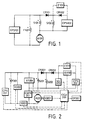
- a separately-excited field winding F101 can be added to provide a compound motor, which also includes the above pair of series excitation field windings.
- a main series excitation field winding S101 is in series with an armature A101, and is driven by a main power source CPS101.
- a blocking diode CR101 is connected in series between the power source end of the main winding S101 and an auxiliary series excitation field winding S102, with the polarity arranged so as to prevent an auxiliary excitation power source CPS102 from exciting the main winding S101, while allowing the auxiliary winding S102 to be excited by both the main power source CPS101 and the auxiliary power source CPS102.
- a diode CR102 is positioned in series between the auxiliary power supply CPS102 and the auxiliary winding S102.
- the main power source CPS101 can be either a storage battery, a solar energy converter, or a DC generator, or may be obtained from the rectification of an AC power source or other DC power source.
- the auxiliary power source CPS102 may also be a single voltage or variable output voltage DC power supply, such as a storage battery, a solar energy converter or a DC generator, or may be obtained from the rectification of an AC power source or other DC power source.
- the above circuit may also include components for detecting the state of operation of the motor, and the voltage and current of the power supply, and which are connected jointly to a central control circuit and to a control interface to form a more precise circuit system providing feedback functions.
- the improved driving circuit includes at least two series excitation field windings, one end of each of the series excitation windings being jointly connected, with the same polarity, to the armature, and at least one of the series excitation field windings is isolated by means of diodes so as to receive power from different power sources.
- the two series excitation field windings replace the conventional single series excitation field winding.
- a separately excited field winding F201 can be included to provide a compound motor, which also includes the above pair of series excitation field windings.
- a main series excitation field winding S201 is in series with an armature A201 and is driven by a main power source CPS201.
- a blocking diode CR201 is connected in series between the power source end of the main winding S201 and an auxiliary series excitation field winding S202 with the polarity arranged so as to prevent an auxiliary excitation power supply CPS202 from exciting the main series windings S201, while allowing the auxiliary winding S202 to be excited by the main power source CPS201 and the auxiliary power source CPS202.
- a diode CR202 is positioned in series between the auxiliary power supply CPS202 and the auxiliary winding S102.
- the main power source CPS201 can be either a single voltage or variable output voltage DC power source, such as a storage battery, a solar energy converter, or a DC generator, or may be obtained from the rectification of an AC power source or other DC power source.
- the auxiliary power source CPS202 may also be a single voltage or variable output voltage DC power supply, such as a storage battery, a solar energy converter, or a DC generator, or may be obtained from the rectification of an AC power source or other DC power source.
- the feedback detection components of this embodiment include one or more of the following components; a main power supply voltage detection component VD201, an armature current detection component ID201, an armature counter electromotive force (EMF) detection component EMFD201, a motor rotational speed detection component SD201, an auxiliary excitation voltage detection component VD202, an auxiliary excitation current detection component ID202, and a series excitation field voltage drop detection component VS201.
- a main power supply voltage detection component VD201 an armature current detection component ID201, an armature counter electromotive force (EMF) detection component EMFD201, a motor rotational speed detection component SD201, an auxiliary excitation voltage detection component VD202, an auxiliary excitation current detection component ID202, and a series excitation field voltage drop detection component VS201.
- EMF electromotive force
- the control unit CCU201 which may of the analogue type or digital type, includes electromechanical and/or solid state components for allowing control of the output voltages and currents of the main power source and the auxiliary excitation power source by referring to the setting of the input control unit and the signals from the feedback detection component in known fashion.
- a current limiting adjustment element Z101, Z202 may be connected in parallel to the two ends of the blocking diode CR102 or to the current detector ID202 of the auxiliary power source and the auxiliary series excitation field winding. As the main excitation current increases, and the voltage drop across the two ends of the main series excitation winding exceeds the voltage provided by the auxiliary power source, a counter current will be formed which charges the auxiliary storage elements.
- the current limiting adjustment element allows adjustment of the counter current.
- the current limiting adjustment element Z201 of Figure 2 may be constituted by a resistance element, by an electromechanical or solid state element to be controlled by the central control unit CCU201 to adjust the charging current passing through the storage power element.
- the present invention is an innovative design, which raises the efficiency of a series excitation motor of the type used widely in the industrial world, and provides improved speed regulation.
Landscapes
- Engineering & Computer Science (AREA)
- Power Engineering (AREA)
- Control Of Direct Current Motors (AREA)
- Electrical Control Of Air Or Fuel Supplied To Internal-Combustion Engine (AREA)
- Control Of The Air-Fuel Ratio Of Carburetors (AREA)
- Valve Device For Special Equipments (AREA)
- Synchronous Machinery (AREA)
- Control Of Eletrric Generators (AREA)
- Protection Of Generators And Motors (AREA)
Claims (4)
- Motorsteuerschaltung mit einer Hauptenergieversorgung (CPS101, CPS201), einem Anker (A101, A201), einer Hauptreihenwicklung (S101, S201), die in Reihe zum Anker und zur Hauptenergieversorgung geschaltet ist, und einer Hilfsreihenwicklung (S102, S202), die parallel zwischen die Hauptreihenwicklung und eine Hilfsenergieversorgung (CPS102, CPS202) geschaltet ist, wobei ein erstes Ende der Hilfsreihenwicklung mit einem ersten Ende der Hauptreihenwicklung, mit dem Anker und mit einem Anschluß der Hilfsenergieversorgung verbunden ist, und ein zweites Ende der Hilfsreihenwicklung über eine erste Diode (CR101, CR201) mit einem zweiten Ende der Hauptreihenwicklung und über eine zweite Diode (CR102, CR202) mit einem zweiten Anschluß der Hilfsenergieversorgung verbunden ist, welche erste und zweite Diode so vorgespannt sind, daß das zweite Ende der Hilfsreihenwicklung so geschaltet ist, daß es Strom sowohl von der Haupt- als auch der Hilfsenergieversorgung aufnimmt und dadurch der Ankerstrom für eine verbesserte Steuerung bei leichter Last und bei Überlastverhältnissen erhöht ist.
- Motorsteuerschaltung nach Anspruch 1, welche weiterhin eine Nebenschlußfeldwicklung (F101, F201) zur Bildung einer Kompoundmotorsteuerschaltung umfaßt.
- Motorsteuerschaltung nach Anspruch 1 oder Anspruch 2, welche weiterhin eine zentrale Steuereinheit (CCU201) umfaßt, die so ausgebildet ist, daß sie die Ausgangsleistung der Haupt- und/oder Hilfsenergieversorgung (CPS201, CPS202) auf ein Rückkopplungssignal von wenigstens einer Erfassungskomponente ansprechend ändert, die aus einer Gruppe gewählt ist, die aus einer Erfassungskomponente (VD201) für die Hauptenergieversorgungsspannung, einer Erfassungskomponente (ID201) für den Ankerstrom, einer Erfassungskomponente (EMFD201) für die gegenelektromotorische Kraft des Ankers, einer Erfassungskomponente (SD201) für die Motordrehgeschwindigkeit, einer Erfassungskomponente (VD202) für eine Hilfserregungsspannung, einer Erfassungskomponente (ID202) für einen Hilfserregungsstrom und eine Erfassungskomponente (VS201) für den Wert des Reihenerregungsfeldspannungsabfalls besteht.
- Motorsteuerschaltung nach einem der Ansprüche 1 bis 3, welcher weiterhin ein strombegrenzendes Einstellelement (Z101, Z201) umfaßt, das zwischen die Hilfsreihenwicklung (S102, S202) und die Hilfsenergieversorgung (CPS102, CPS202) geschaltet ist, um einen Ladestrom zwischen der Hauptreihenwicklung (S101, S201) und der Hilfsenergieversorgung fließen zu lassen, wenn der Spannungsabfall über der Hauptreihenwicklung die Spannung überschreitet, die von der Hilfsenergieversorgung geliefert wird.
Applications Claiming Priority (2)
| Application Number | Priority Date | Filing Date | Title |
|---|---|---|---|
| GB9216579 | 1992-08-05 | ||
| GB9216579A GB2269498A (en) | 1992-08-05 | 1992-08-05 | Electric motor control arrangement |
Publications (3)
| Publication Number | Publication Date |
|---|---|
| EP0582467A2 EP0582467A2 (de) | 1994-02-09 |
| EP0582467A3 EP0582467A3 (de) | 1994-02-23 |
| EP0582467B1 true EP0582467B1 (de) | 1997-10-22 |
Family
ID=10719825
Family Applications (1)
| Application Number | Title | Priority Date | Filing Date |
|---|---|---|---|
| EP93306151A Expired - Lifetime EP0582467B1 (de) | 1992-08-05 | 1993-08-04 | Motorsteuerung |
Country Status (6)
| Country | Link |
|---|---|
| US (1) | US5446352A (de) |
| EP (1) | EP0582467B1 (de) |
| AT (1) | ATE159628T1 (de) |
| DE (1) | DE69314722T2 (de) |
| ES (1) | ES2108230T3 (de) |
| GB (1) | GB2269498A (de) |
Families Citing this family (3)
| Publication number | Priority date | Publication date | Assignee | Title |
|---|---|---|---|---|
| US6768278B2 (en) * | 2002-08-06 | 2004-07-27 | Honeywell International, Inc. | Gas turbine engine starter generator with switchable exciter stator windings |
| JP4398312B2 (ja) * | 2004-07-06 | 2010-01-13 | 矢崎総業株式会社 | 半導体スイッチの制御装置 |
| US9178396B2 (en) * | 2012-06-11 | 2015-11-03 | Tai-Her Yang | Cross-interlocked switch type DC electric machine having auxiliary excitation winding and conduction ring and brush |
Family Cites Families (13)
| Publication number | Priority date | Publication date | Assignee | Title |
|---|---|---|---|---|
| GB495893A (en) * | 1936-06-27 | 1938-11-22 | Cantieri Riuniti Adriatico Sa | Improvements in or relating to the starting of direct current motors |
| DE1146187B (de) * | 1962-01-09 | 1963-03-28 | Licentia Gmbh | Gleichstromkreis mit durch elektronische Mittel umsteuerbarer Energieaustausch-richtung |
| US3336516A (en) * | 1965-02-15 | 1967-08-15 | Ite Circuit Breaker Ltd | Control circuit for d-c motors having dual series field windings |
| GB1315851A (en) * | 1970-02-09 | 1973-05-02 | British Railways Board | Direct current motors including series field windings |
| GB1353490A (en) * | 1971-07-30 | 1974-05-15 | Toyo Kogyo Co | Control system for electric automotive vehicles |
| IT1062833B (it) * | 1976-05-26 | 1985-02-11 | Fiat Spa | Dispositivo per il controllo della eccitazione di una macchina elettrica a corrente continua |
| US4330742A (en) * | 1980-04-11 | 1982-05-18 | Eberhart Reimers | Circuitry for recovering electrical energy with an electric vehicle DC propulsion motor when braking |
| CA1199675A (en) * | 1983-03-31 | 1986-01-21 | Canadian General Electric Company Limited | Speed controller for mill drives and the like |
| US4751439A (en) * | 1983-05-16 | 1988-06-14 | Caterpillar Industrial Inc. | Multiple chopper speed control system for compound motor |
| US4490665A (en) * | 1983-07-26 | 1984-12-25 | Beckman Instruments, Inc. | Method for driving a stepper motor |
| US4500819A (en) * | 1983-11-09 | 1985-02-19 | Clark Equipment Company | Auxiliary electric power supply for electric work vehicles |
| US4639647A (en) * | 1984-04-04 | 1987-01-27 | Posma Bonne W | Four quadrant control of series motors |
| US4716487A (en) * | 1986-05-05 | 1987-12-29 | Automeg, Inc. | Apparatus for monitoring motor winding leakage |
-
1992
- 1992-08-05 GB GB9216579A patent/GB2269498A/en not_active Withdrawn
-
1993
- 1993-08-04 ES ES93306151T patent/ES2108230T3/es not_active Expired - Lifetime
- 1993-08-04 DE DE69314722T patent/DE69314722T2/de not_active Expired - Fee Related
- 1993-08-04 EP EP93306151A patent/EP0582467B1/de not_active Expired - Lifetime
- 1993-08-04 AT AT93306151T patent/ATE159628T1/de not_active IP Right Cessation
- 1993-08-05 US US08/102,295 patent/US5446352A/en not_active Expired - Fee Related
Also Published As
| Publication number | Publication date |
|---|---|
| ES2108230T3 (es) | 1997-12-16 |
| US5446352A (en) | 1995-08-29 |
| EP0582467A2 (de) | 1994-02-09 |
| ATE159628T1 (de) | 1997-11-15 |
| EP0582467A3 (de) | 1994-02-23 |
| GB9216579D0 (en) | 1992-09-16 |
| DE69314722D1 (de) | 1997-11-27 |
| DE69314722T2 (de) | 1998-06-04 |
| GB2269498A (en) | 1994-02-09 |
Similar Documents
| Publication | Publication Date | Title |
|---|---|---|
| CA1214511A (en) | Method and circuit for dc motor field regulation with speed feedback | |
| US4829218A (en) | Direct current adjusting device | |
| US4542323A (en) | Direct current motor without commutator | |
| GB1581357A (en) | Optimized electric motor having controlled magnetic flux density | |
| EP0582467B1 (de) | Motorsteuerung | |
| JP3051192U (ja) | コンデンサ調節式可制御電圧電流電源回路 | |
| EP0765021A1 (de) | Spannungsreglerschaltung für einen Dauermagnet-Wechselstromgenerator | |
| EP0582417B1 (de) | Verfahren und Schaltungsanordnung für eine Reihenschluss- oder Kompound-erregte Gleichstrommaschine | |
| US4458182A (en) | Drive device with two mutually counteracting motors for eliminating gearing backlash | |
| US5569992A (en) | DC shunt (or compound) motor and its related circuit with controllable dynamic characteristics | |
| US5453673A (en) | DC motor with auxiliary exciting power supply for switching-on series (or compound) start of shunt normal operation according to the load | |
| EP0638990A1 (de) | Verfahren und Schaltungsanordnung mit verdoppelter Spannung für Reihenschluss- oder Kompound- Motor | |
| EP0632573B1 (de) | Gleichstrommotor mit zusätzlicher Erregungsstromversorgung, der während des Normalbetriebs als Reihenschluss- (oder Kompound-)motor und während des Normalbetriebs in Abhängigkeit von der Last als Nebenschlussmotor arbeitet | |
| JP3123869B2 (ja) | 直流分巻電動機の制御装置 | |
| JPH09182415A (ja) | 大電力昇圧チョッパ回路 | |
| JP3320854B2 (ja) | 複電圧駆動モータの制御方法及び制御回路 | |
| KR830002573Y1 (ko) | 제어 재생식 직류전원 | |
| US5410231A (en) | Auxiliary power supply circuit for a series motor | |
| RU2032264C1 (ru) | Электропривод постоянного тока | |
| KR20010011524A (ko) | 에스알엠의 과전류 보호회로 | |
| JPH07107769A (ja) | 複電圧駆動直流回転機の制御方法及び制御回路 | |
| SU1251275A1 (ru) | Широтно-импульсный регул тор частоты вращени электродвигател посто нного тока | |
| JPS6026678B2 (ja) | 電動ドライバ−の制御装置 | |
| SU1684903A1 (ru) | Многодвигательный электропривод | |
| JPH07123668A (ja) | 複数の直列界磁巻線を持った電動機 |
Legal Events
| Date | Code | Title | Description |
|---|---|---|---|
| PUAI | Public reference made under article 153(3) epc to a published international application that has entered the european phase |
Free format text: ORIGINAL CODE: 0009012 |
|
| PUAL | Search report despatched |
Free format text: ORIGINAL CODE: 0009013 |
|
| AK | Designated contracting states |
Kind code of ref document: A2 Designated state(s): AT BE CH DE DK ES FR GB IT LI NL SE |
|
| AK | Designated contracting states |
Kind code of ref document: A3 Designated state(s): AT BE CH DE DK ES FR GB IT LI NL SE |
|
| 17P | Request for examination filed |
Effective date: 19940802 |
|
| 17Q | First examination report despatched |
Effective date: 19960318 |
|
| GRAG | Despatch of communication of intention to grant |
Free format text: ORIGINAL CODE: EPIDOS AGRA |
|
| GRAH | Despatch of communication of intention to grant a patent |
Free format text: ORIGINAL CODE: EPIDOS IGRA |
|
| GRAH | Despatch of communication of intention to grant a patent |
Free format text: ORIGINAL CODE: EPIDOS IGRA |
|
| GRAA | (expected) grant |
Free format text: ORIGINAL CODE: 0009210 |
|
| AK | Designated contracting states |
Kind code of ref document: B1 Designated state(s): AT BE CH DE DK ES FR GB IT LI NL SE |
|
| PG25 | Lapsed in a contracting state [announced via postgrant information from national office to epo] |
Ref country code: NL Free format text: LAPSE BECAUSE OF FAILURE TO SUBMIT A TRANSLATION OF THE DESCRIPTION OR TO PAY THE FEE WITHIN THE PRESCRIBED TIME-LIMIT Effective date: 19971022 Ref country code: LI Free format text: LAPSE BECAUSE OF FAILURE TO SUBMIT A TRANSLATION OF THE DESCRIPTION OR TO PAY THE FEE WITHIN THE PRESCRIBED TIME-LIMIT Effective date: 19971022 Ref country code: DK Free format text: LAPSE BECAUSE OF NON-PAYMENT OF DUE FEES Effective date: 19971022 Ref country code: CH Free format text: LAPSE BECAUSE OF FAILURE TO SUBMIT A TRANSLATION OF THE DESCRIPTION OR TO PAY THE FEE WITHIN THE PRESCRIBED TIME-LIMIT Effective date: 19971022 Ref country code: BE Free format text: LAPSE BECAUSE OF FAILURE TO SUBMIT A TRANSLATION OF THE DESCRIPTION OR TO PAY THE FEE WITHIN THE PRESCRIBED TIME-LIMIT Effective date: 19971022 Ref country code: AT Free format text: LAPSE BECAUSE OF FAILURE TO SUBMIT A TRANSLATION OF THE DESCRIPTION OR TO PAY THE FEE WITHIN THE PRESCRIBED TIME-LIMIT Effective date: 19971022 |
|
| REF | Corresponds to: |
Ref document number: 159628 Country of ref document: AT Date of ref document: 19971115 Kind code of ref document: T |
|
| REG | Reference to a national code |
Ref country code: CH Ref legal event code: EP |
|
| REF | Corresponds to: |
Ref document number: 69314722 Country of ref document: DE Date of ref document: 19971127 |
|
| REG | Reference to a national code |
Ref country code: ES Ref legal event code: FG2A Ref document number: 2108230 Country of ref document: ES Kind code of ref document: T3 |
|
| ET | Fr: translation filed | ||
| ITF | It: translation for a ep patent filed | ||
| PG25 | Lapsed in a contracting state [announced via postgrant information from national office to epo] |
Ref country code: SE Effective date: 19980122 |
|
| NLV1 | Nl: lapsed or annulled due to failure to fulfill the requirements of art. 29p and 29m of the patents act | ||
| REG | Reference to a national code |
Ref country code: CH Ref legal event code: PL |
|
| PLBE | No opposition filed within time limit |
Free format text: ORIGINAL CODE: 0009261 |
|
| STAA | Information on the status of an ep patent application or granted ep patent |
Free format text: STATUS: NO OPPOSITION FILED WITHIN TIME LIMIT |
|
| 26N | No opposition filed | ||
| PGFP | Annual fee paid to national office [announced via postgrant information from national office to epo] |
Ref country code: GB Payment date: 19990806 Year of fee payment: 7 |
|
| PGFP | Annual fee paid to national office [announced via postgrant information from national office to epo] |
Ref country code: ES Payment date: 19990817 Year of fee payment: 7 |
|
| PGFP | Annual fee paid to national office [announced via postgrant information from national office to epo] |
Ref country code: FR Payment date: 19990831 Year of fee payment: 7 Ref country code: DE Payment date: 19990831 Year of fee payment: 7 |
|
| PG25 | Lapsed in a contracting state [announced via postgrant information from national office to epo] |
Ref country code: GB Free format text: LAPSE BECAUSE OF NON-PAYMENT OF DUE FEES Effective date: 20000804 |
|
| PG25 | Lapsed in a contracting state [announced via postgrant information from national office to epo] |
Ref country code: ES Free format text: LAPSE BECAUSE OF NON-PAYMENT OF DUE FEES Effective date: 20000805 |
|
| GBPC | Gb: european patent ceased through non-payment of renewal fee |
Effective date: 20000804 |
|
| PG25 | Lapsed in a contracting state [announced via postgrant information from national office to epo] |
Ref country code: FR Free format text: LAPSE BECAUSE OF NON-PAYMENT OF DUE FEES Effective date: 20010430 |
|
| PG25 | Lapsed in a contracting state [announced via postgrant information from national office to epo] |
Ref country code: DE Free format text: LAPSE BECAUSE OF NON-PAYMENT OF DUE FEES Effective date: 20010501 |
|
| REG | Reference to a national code |
Ref country code: FR Ref legal event code: ST |
|
| REG | Reference to a national code |
Ref country code: ES Ref legal event code: FD2A Effective date: 20010911 |
|
| PG25 | Lapsed in a contracting state [announced via postgrant information from national office to epo] |
Ref country code: IT Free format text: LAPSE BECAUSE OF NON-PAYMENT OF DUE FEES Effective date: 20050804 |