US6150789A - Stepper motor control - Google Patents
Stepper motor control Download PDFInfo
- Publication number
- US6150789A US6150789A US09/323,467 US32346799A US6150789A US 6150789 A US6150789 A US 6150789A US 32346799 A US32346799 A US 32346799A US 6150789 A US6150789 A US 6150789A
- Authority
- US
- United States
- Prior art keywords
- stepper motor
- voltage
- voltage output
- motor control
- driver
- Prior art date
- Legal status (The legal status is an assumption and is not a legal conclusion. Google has not performed a legal analysis and makes no representation as to the accuracy of the status listed.)
- Expired - Fee Related
Links
- 230000007423 decrease Effects 0.000 claims description 4
- 238000000034 method Methods 0.000 description 5
- 230000001133 acceleration Effects 0.000 description 2
- 238000010586 diagram Methods 0.000 description 2
- 230000006870 function Effects 0.000 description 2
- 238000007689 inspection Methods 0.000 description 2
- 238000012360 testing method Methods 0.000 description 2
- 238000004804 winding Methods 0.000 description 2
- 241001562081 Ikeda Species 0.000 description 1
- 238000010276 construction Methods 0.000 description 1
- 230000001419 dependent effect Effects 0.000 description 1
- 238000013461 design Methods 0.000 description 1
- 238000004146 energy storage Methods 0.000 description 1
- 238000012544 monitoring process Methods 0.000 description 1
- 238000013021 overheating Methods 0.000 description 1
- 230000001502 supplementing effect Effects 0.000 description 1
Images


Classifications
-
- H—ELECTRICITY
- H02—GENERATION; CONVERSION OR DISTRIBUTION OF ELECTRIC POWER
- H02P—CONTROL OR REGULATION OF ELECTRIC MOTORS, ELECTRIC GENERATORS OR DYNAMO-ELECTRIC CONVERTERS; CONTROLLING TRANSFORMERS, REACTORS OR CHOKE COILS
- H02P8/00—Arrangements for controlling dynamo-electric motors rotating step by step
- H02P8/36—Protection against faults, e.g. against overheating or step-out; Indicating faults
-
- G—PHYSICS
- G05—CONTROLLING; REGULATING
- G05B—CONTROL OR REGULATING SYSTEMS IN GENERAL; FUNCTIONAL ELEMENTS OF SUCH SYSTEMS; MONITORING OR TESTING ARRANGEMENTS FOR SUCH SYSTEMS OR ELEMENTS
- G05B19/00—Programme-control systems
- G05B19/02—Programme-control systems electric
- G05B19/18—Numerical control [NC], i.e. automatically operating machines, in particular machine tools, e.g. in a manufacturing environment, so as to execute positioning, movement or co-ordinated operations by means of programme data in numerical form
- G05B19/19—Numerical control [NC], i.e. automatically operating machines, in particular machine tools, e.g. in a manufacturing environment, so as to execute positioning, movement or co-ordinated operations by means of programme data in numerical form characterised by positioning or contouring control systems, e.g. to control position from one programmed point to another or to control movement along a programmed continuous path
- G05B19/40—Open loop systems, e.g. using stepping motor
-
- H—ELECTRICITY
- H02—GENERATION; CONVERSION OR DISTRIBUTION OF ELECTRIC POWER
- H02P—CONTROL OR REGULATION OF ELECTRIC MOTORS, ELECTRIC GENERATORS OR DYNAMO-ELECTRIC CONVERTERS; CONTROLLING TRANSFORMERS, REACTORS OR CHOKE COILS
- H02P8/00—Arrangements for controlling dynamo-electric motors rotating step by step
- H02P8/14—Arrangements for controlling speed or speed and torque
-
- H—ELECTRICITY
- H02—GENERATION; CONVERSION OR DISTRIBUTION OF ELECTRIC POWER
- H02P—CONTROL OR REGULATION OF ELECTRIC MOTORS, ELECTRIC GENERATORS OR DYNAMO-ELECTRIC CONVERTERS; CONTROLLING TRANSFORMERS, REACTORS OR CHOKE COILS
- H02P8/00—Arrangements for controlling dynamo-electric motors rotating step by step
- H02P8/32—Reducing overshoot or oscillation, e.g. damping
-
- G—PHYSICS
- G05—CONTROLLING; REGULATING
- G05B—CONTROL OR REGULATING SYSTEMS IN GENERAL; FUNCTIONAL ELEMENTS OF SUCH SYSTEMS; MONITORING OR TESTING ARRANGEMENTS FOR SUCH SYSTEMS OR ELEMENTS
- G05B2219/00—Program-control systems
- G05B2219/30—Nc systems
- G05B2219/41—Servomotor, servo controller till figures
- G05B2219/41326—Step motor
-
- G—PHYSICS
- G05—CONTROLLING; REGULATING
- G05B—CONTROL OR REGULATING SYSTEMS IN GENERAL; FUNCTIONAL ELEMENTS OF SUCH SYSTEMS; MONITORING OR TESTING ARRANGEMENTS FOR SUCH SYSTEMS OR ELEMENTS
- G05B2219/00—Program-control systems
- G05B2219/30—Nc systems
- G05B2219/42—Servomotor, servo controller kind till VSS
- G05B2219/42198—Step motor driven by step size and step duration data
Definitions
- the present invention relates to stepper motor controls generally and, more particularly, but not by way of limitation, to an improved stepper motor control that increases drive voltage as step rate increases, while maintaining frame temperature of the motor relatively constant, and that produces very low levels of electromagnetic interference (EMI) and radio frequency interference (RFI).
- EMI electromagnetic interference
- RFID radio frequency interference
- Stepper motors suffer from a well-known problem in that, as step rate increases, the impedance of the motor windings and the generated back EMF increases, causing current and performance to drop off.
- control systems either do not adequately address the problem, are expensive, are complicated, and/or address entirely different problems.
- Another object of the invention is to provide such a stepper motor control that produces very low levels of EMI/RFI.
- a stepper motor control comprising: driver means to drive said stepper motor; detecting means to detect a commanded step rate signal provided to said driver means and to provide a first output signal proportional thereto; voltage control means, responsive to said first output signal, to provide driving power to said driver means, and to increase voltage to said driver means in proportion to an increase in magnitude of said first output signal to maintain constant power to said stepper motor. Voltage control can be effected either on the drive board or by controlling the power supply.
- An additional feature provides over-current protection for said stepper motor during a lock rotor (stall) condition.
- the stepper motor control produces very low levels of EMI/RFI as compared with PWM current control (chopper) drives.
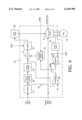
- FIG. 1 is a block diagram of the major elements of a stepper motor control constructed according to one embodiment of the present invention.
- FIG. 2 is a graph of torque versus step rate for a motor driven with the stepper motor control of FIG. 1 compared with the motor controlled by conventional means.
- FIG. 3 is a graph of torque versus step rate for a motor driven with the stepper control of FIG. 1 compared with similar motors controlled by conventional means.
- FIG. 4 is a block diagram of the major elements of a stepper motor control constructed according to another embodiment of the present invention.
- FIG. 1 illustrates a stepper motor control 10 constructed according to one embodiment of the present invention.
- a step rate command is inputted to an oscillator 12 which outputs a pulse train which is inputted to an L/R type driver 14 which also receives a direction input and which drives a stepper motor 16 in a conventional manner.
- An external pulse train can be used instead of the on-board oscillator 12 by placement of a jumper 18.
- the pulse train from oscillator 12 is also inputted to a frequency-to-voltage converter 20 which outputs a voltage proportional to the pulse rate.
- a voltage follower 22 is provided at the output of frequency-to-voltage converter 20 to serve as a buffer.
- the voltage signal from frequency-to-voltage converter 20 and a voltage output from an adjustable voltage reference 30 are added in a voltage summing amplifier 32 and the output of the summer is amplified in an amplifier 34.
- the adjustable voltage reference 30 is set depending on the desired zero-step-rate voltage for motor 16; that is, for example, whether the motor will be denominated a "5-volt” motor or a "12-volt” motor.
- the output of amplifier 34 is inputted to a voltage controller 40 which connects an external power supply 42 to the driver 14.
- the key to a major object of the invention is setting the gain of amplifier 34 such that the voltage to motor 16 will increase as step rate increases, but that the frame temperature rise of the stepper motor will remain relatively constant. It has been found that this is easily accomplished by the trial-and-error testing of two or three data points for a particular motor type and size under consideration and measuring frame temperature rise. It is to be noted that the design procedure is required to be performed only once for each unique type or size of motor.
- stepper motor 16 can operate from one single output linear power supply 42 and it will be understood that, typically, the components of system 10 will be disposed on a printed circuit, or "driver”, board.
- FIG. 2 illustrates a curve 50 of torque versus step rate for a 5-volt, 1.0" can stack permanent magnet (or “tin can”) stepper motor, as supplied by Haydon Switch & Instrument, Waterbury, Conn., driven by control 10 (FIG. 1), and operated at a relatively constant 75 Centigrade degree temperature rise.
- control 10 FIG. 1
- FIG. 2 illustrates a curve 52 for the same motor driven by a chopper drive at the same constant frame temperature rise and a curve 54 for the same motor driven by a conventional L/R drive at constant voltage. In the latter case, frame temperature decreases at higher step rates.
- FIG. 1 illustrates a curve 50 of torque versus step rate for a 5-volt, 1.0" can stack permanent magnet (or “tin can”) stepper motor, as supplied by Haydon Switch & Instrument, Waterbury, Conn., driven by control 10 (FIG. 1), and operated at a relatively constant 75 Centigrade degree temperature rise.
- curve 52 for the same motor driven by a chopper drive at
- FIG. 3 illustrates a curve 60 of torque versus step rate for a 5-volt, 1.4" can stack permanent magnet (or “tin can”) stepper motor, also supplied by Haydon Switch & Instrument, Waterbury, Conn., driven by control 10 (FIG. 1), and operated at a relatively constant 75 Centigrade degree temperature rise.
- a curve 62 for a 3-volt motor of the same type and size driven by a chopper drive at the same constant frame temperature rise and a curve 64 for a 12-volt motor of the same type and size driven by a conventional L/R drive at constant voltage.
- curve 54 FIG. 2
- frame temperature decreases at higher step rates.
- control 10 improves the improvement in performance through the use of control 10 is evident from inspection of FIG. 3, with the motor driven by control 10 producing greater power than the motor driven by a chopper drive or a conventional L/R drive, and, again, the useful step rate range of the motor with the inventive drive is extended greatly beyond that of the motor using a chopper drive or a conventional L/R drive.
- an optional overcurrent safety feature to prevent dangerous overheating of motor 16 if the motor is in a locked rotor condition, in which safety feature a current sense circuit 70 measures current flow in motor 16 and outputs a voltage proportional to the current flow. This voltage is compared to a reference voltage in a first comparator 72 which outputs a disable signal to voltage reference 30, reducing the input to amplifier 34 to only the voltage proportional to step rate from frequency-to-voltage converter 20. The output of first comparator 72 could also be used to cut off power from power supply 42 or to disable the output of driver 14.
- a second comparator 80 keeps the output of first comparator 72 disabled until the voltage proportional to step rate from frequency-to-voltage converter 20 exceeds a reference voltage. This allows overcurrent protection only above a set step rate. Also, an optional passive (RC) circuit can automatically cycle the enable signal to adjustable voltage reference 30 to provide "full" power (based on commanded step rate) to motor 16 for a set time period in case the overload condition on the motor has cleared. Cycle on/off times can be easily set.
- RC passive
- FIG. 4 illustrates a stepper motor control 10' constructed according to another embodiment of the present invention. Elements of control 10' having functions similar to like elements of control 10 (FIG. 1) are given the same reference numerals as for control 10. The foregoing description of control 10 should be consulted for a discussion of those functions.
- control 10' The difference between control 10' and control 10 is that, whereas control 10 included a voltage controller 40, that element has been omitted from control 10' and control of the voltage provided to driver 14 is effected by the control of power supply 90, with the output of amplifier 34 being inputted directly to the power supply.
- This is a somewhat more efficient arrangement than that of control 10 and there is less heat to dissipate in the driver board. Disadvantages are that two extra wires going to power supply are required and the power supply has to be modified by conventional means to accept the output from amplifier 34.
- Performance of a system including control 10' can be expected to be at least as good as that shown on FIGS. 2 and 3 for systems including control 10.
Landscapes
- Engineering & Computer Science (AREA)
- Power Engineering (AREA)
- Human Computer Interaction (AREA)
- Manufacturing & Machinery (AREA)
- Physics & Mathematics (AREA)
- General Physics & Mathematics (AREA)
- Automation & Control Theory (AREA)
- Control Of Stepping Motors (AREA)
Abstract
Description
Claims (19)
Priority Applications (1)
| Application Number | Priority Date | Filing Date | Title |
|---|---|---|---|
| US09/323,467 US6150789A (en) | 1999-02-13 | 1999-06-01 | Stepper motor control |
Applications Claiming Priority (2)
| Application Number | Priority Date | Filing Date | Title |
|---|---|---|---|
| US25021899A | 1999-02-13 | 1999-02-13 | |
| US09/323,467 US6150789A (en) | 1999-02-13 | 1999-06-01 | Stepper motor control |
Related Parent Applications (1)
| Application Number | Title | Priority Date | Filing Date |
|---|---|---|---|
| US25021899A Continuation-In-Part | 1999-02-13 | 1999-02-13 |
Publications (1)
| Publication Number | Publication Date |
|---|---|
| US6150789A true US6150789A (en) | 2000-11-21 |
Family
ID=22946814
Family Applications (1)
| Application Number | Title | Priority Date | Filing Date |
|---|---|---|---|
| US09/323,467 Expired - Fee Related US6150789A (en) | 1999-02-13 | 1999-06-01 | Stepper motor control |
Country Status (1)
| Country | Link |
|---|---|
| US (1) | US6150789A (en) |
Cited By (22)
| Publication number | Priority date | Publication date | Assignee | Title |
|---|---|---|---|---|
| US20020079856A1 (en) * | 2000-11-27 | 2002-06-27 | Hill Christopher L. | Motor start-up current control apparatus and method |
| EP1221751A2 (en) * | 2001-01-04 | 2002-07-10 | Hewlett-Packard Company | Motor driver protector |
| US6586898B2 (en) | 2001-05-01 | 2003-07-01 | Magnon Engineering, Inc. | Systems and methods of electric motor control |
| US20030214265A1 (en) * | 2002-05-20 | 2003-11-20 | Vanderzee Joel C. | Stepper driver system with current feedback |
| US20040218320A1 (en) * | 2001-10-05 | 2004-11-04 | Strike Nigel David | Motor control circuit overcurrent protection |
| US20050140327A1 (en) * | 2003-12-30 | 2005-06-30 | Xerox Corporation | Method and apparatus for detecting a stalled stepper motor |
| FR2865323A1 (en) * | 2004-01-20 | 2005-07-22 | Valeo Vision | DC electrical motor controlling process for motor vehicle, involves varying control parameter e.g. frequency, of control circuit that is utilized for controlling direct current electric motor in motor vehicle |
| US20050206340A1 (en) * | 2004-03-17 | 2005-09-22 | Alan Brundle | System and method for controlling current provided to a stepping motor |
| US20080067969A1 (en) * | 2005-07-08 | 2008-03-20 | Matsushita Electric Industrial Co., Ltd. | Stepping motor driving apparatus and stepping motor driving method |
| CN101888207A (en) * | 2009-05-14 | 2010-11-17 | 多拉股份公司 | In feed-forward voltage mode, drive the method and the hardware system of stepping motor |
| US20110181229A1 (en) * | 2009-12-18 | 2011-07-28 | Gordan Galic | Apparatus, system and method for stepper motor stall detection |
| CN101414745B (en) * | 2007-10-18 | 2011-09-21 | 茂达电子股份有限公司 | Motor protection device and method |
| US8069772B1 (en) | 2008-06-18 | 2011-12-06 | Arnold Peterson | Systems and methods for controlling hydraulic actuators |
| US8109197B1 (en) | 2008-06-18 | 2012-02-07 | Arnold Peterson | Hydraulic control system and method |
| EP2450761A1 (en) * | 2010-11-05 | 2012-05-09 | Compliss | Apparatus and process for diving a closing device comprising a stepper motor |
| US8421368B2 (en) | 2007-07-31 | 2013-04-16 | Lsi Industries, Inc. | Control of light intensity using pulses of a fixed duration and frequency |
| US8604709B2 (en) | 2007-07-31 | 2013-12-10 | Lsi Industries, Inc. | Methods and systems for controlling electrical power to DC loads |
| CN104092418A (en) * | 2014-06-13 | 2014-10-08 | 中国科学院西安光学精密机械研究所 | Control device and method for stepping motor |
| US8903577B2 (en) | 2009-10-30 | 2014-12-02 | Lsi Industries, Inc. | Traction system for electrically powered vehicles |
| US9013133B2 (en) | 2011-06-02 | 2015-04-21 | Visteon Global Technologies, Inc. | Method and apparatus for stepper motor stall detection |
| CN104092418B (en) * | 2014-06-13 | 2016-11-30 | 中国科学院西安光学精密机械研究所 | Control device and method for stepping motor |
| CN108933550A (en) * | 2018-08-30 | 2018-12-04 | 深圳市万至达电机制造有限公司 | A kind of control circuit and its control method of integral type mixing step-servo motor |
Citations (18)
| Publication number | Priority date | Publication date | Assignee | Title |
|---|---|---|---|---|
| US3368128A (en) * | 1964-05-01 | 1968-02-06 | Parrish Instr Ltd | Step motor control circuit including a voltage controlled oscillator |
| US3424961A (en) * | 1966-05-18 | 1969-01-28 | Superior Electric Co | Load responsive,stepping motor speed control circuit |
| US3444447A (en) * | 1966-09-22 | 1969-05-13 | Mesur Matic Electronics Corp | Multi-phase step motor control circuits including means for supplementing the normal energization of the windings |
| US3452263A (en) * | 1967-02-15 | 1969-06-24 | Mesur Matic Electronics Corp | Step motor drive system including current feedback |
| US3505579A (en) * | 1968-01-05 | 1970-04-07 | Superior Electric Co | Power supply for a stepping motor |
| US3662245A (en) * | 1969-12-16 | 1972-05-09 | Mesur Matic Electronics Corp | Control circuit for energizing the windings of multi-phase step motors including a two level supply voltage |
| US3665284A (en) * | 1970-07-20 | 1972-05-23 | Superior Electric Co | Power supply for a stepping motor dependent upon voltage level and pulsing rate |
| US3767990A (en) * | 1972-02-09 | 1973-10-23 | Bridgeport Machines | Control system for producing multi-axis contour movement for a stepping motor drive |
| US3932796A (en) * | 1972-02-09 | 1976-01-13 | Textron, Inc. | Control system for producing multi-axis contour movement for a stepping motor drive |
| US4446412A (en) * | 1981-11-09 | 1984-05-01 | Computervision Corporation | Method and apparatus for controlling stepper motors |
| US4684865A (en) * | 1985-03-25 | 1987-08-04 | Centre Technique Des Industries Mecaniques | Method and device for controlling the acceleration of an electric stepping motor |
| US4788484A (en) * | 1987-08-26 | 1988-11-29 | International Business Machines Corp. | Method and apparatus for driving a stepper motor with multiple voltages |
| US4851755A (en) * | 1988-03-01 | 1989-07-25 | Ampex Corporation | Low power stepper motor drive system and method |
| US5034674A (en) * | 1989-05-17 | 1991-07-23 | Canon Kabushiki Kaisha | Motor driving voltage control device |
| US5216345A (en) * | 1992-05-04 | 1993-06-01 | Hughes Aircraft Company | Mixed mode stepper motor controller and method |
| US5545963A (en) * | 1993-04-01 | 1996-08-13 | Canon Denshi Kabushiki Kaisha | Seek method and apparatus |
| US5648710A (en) * | 1994-11-16 | 1997-07-15 | Canon Kabushiki Kaisha | System for controlling drive of stepping motor |
| US5663624A (en) * | 1992-03-05 | 1997-09-02 | Hewlett-Packard Company | Closed-loop method and apparatus for controlling acceleration and velocity of a stepper motor |
-
1999
- 1999-06-01 US US09/323,467 patent/US6150789A/en not_active Expired - Fee Related
Patent Citations (18)
| Publication number | Priority date | Publication date | Assignee | Title |
|---|---|---|---|---|
| US3368128A (en) * | 1964-05-01 | 1968-02-06 | Parrish Instr Ltd | Step motor control circuit including a voltage controlled oscillator |
| US3424961A (en) * | 1966-05-18 | 1969-01-28 | Superior Electric Co | Load responsive,stepping motor speed control circuit |
| US3444447A (en) * | 1966-09-22 | 1969-05-13 | Mesur Matic Electronics Corp | Multi-phase step motor control circuits including means for supplementing the normal energization of the windings |
| US3452263A (en) * | 1967-02-15 | 1969-06-24 | Mesur Matic Electronics Corp | Step motor drive system including current feedback |
| US3505579A (en) * | 1968-01-05 | 1970-04-07 | Superior Electric Co | Power supply for a stepping motor |
| US3662245A (en) * | 1969-12-16 | 1972-05-09 | Mesur Matic Electronics Corp | Control circuit for energizing the windings of multi-phase step motors including a two level supply voltage |
| US3665284A (en) * | 1970-07-20 | 1972-05-23 | Superior Electric Co | Power supply for a stepping motor dependent upon voltage level and pulsing rate |
| US3932796A (en) * | 1972-02-09 | 1976-01-13 | Textron, Inc. | Control system for producing multi-axis contour movement for a stepping motor drive |
| US3767990A (en) * | 1972-02-09 | 1973-10-23 | Bridgeport Machines | Control system for producing multi-axis contour movement for a stepping motor drive |
| US4446412A (en) * | 1981-11-09 | 1984-05-01 | Computervision Corporation | Method and apparatus for controlling stepper motors |
| US4684865A (en) * | 1985-03-25 | 1987-08-04 | Centre Technique Des Industries Mecaniques | Method and device for controlling the acceleration of an electric stepping motor |
| US4788484A (en) * | 1987-08-26 | 1988-11-29 | International Business Machines Corp. | Method and apparatus for driving a stepper motor with multiple voltages |
| US4851755A (en) * | 1988-03-01 | 1989-07-25 | Ampex Corporation | Low power stepper motor drive system and method |
| US5034674A (en) * | 1989-05-17 | 1991-07-23 | Canon Kabushiki Kaisha | Motor driving voltage control device |
| US5663624A (en) * | 1992-03-05 | 1997-09-02 | Hewlett-Packard Company | Closed-loop method and apparatus for controlling acceleration and velocity of a stepper motor |
| US5216345A (en) * | 1992-05-04 | 1993-06-01 | Hughes Aircraft Company | Mixed mode stepper motor controller and method |
| US5545963A (en) * | 1993-04-01 | 1996-08-13 | Canon Denshi Kabushiki Kaisha | Seek method and apparatus |
| US5648710A (en) * | 1994-11-16 | 1997-07-15 | Canon Kabushiki Kaisha | System for controlling drive of stepping motor |
Cited By (36)
| Publication number | Priority date | Publication date | Assignee | Title |
|---|---|---|---|---|
| US7692394B2 (en) * | 2000-11-27 | 2010-04-06 | Seagate Technology Llc | Power supply output control apparatus and method |
| US20020079856A1 (en) * | 2000-11-27 | 2002-06-27 | Hill Christopher L. | Motor start-up current control apparatus and method |
| EP1221751A2 (en) * | 2001-01-04 | 2002-07-10 | Hewlett-Packard Company | Motor driver protector |
| EP1221751A3 (en) * | 2001-01-04 | 2003-06-18 | Hewlett-Packard Company | Motor driver protector |
| US6586898B2 (en) | 2001-05-01 | 2003-07-01 | Magnon Engineering, Inc. | Systems and methods of electric motor control |
| US20040218320A1 (en) * | 2001-10-05 | 2004-11-04 | Strike Nigel David | Motor control circuit overcurrent protection |
| US20030214265A1 (en) * | 2002-05-20 | 2003-11-20 | Vanderzee Joel C. | Stepper driver system with current feedback |
| US20050140327A1 (en) * | 2003-12-30 | 2005-06-30 | Xerox Corporation | Method and apparatus for detecting a stalled stepper motor |
| US6979972B2 (en) * | 2003-12-30 | 2005-12-27 | Xerox Corporation | Method and apparatus for detecting a stalled stepper motor |
| US20050162876A1 (en) * | 2004-01-20 | 2005-07-28 | Loic Flandre | DC motor driving method for reducing adverse RF interferences and application to a vehicle lighting or signalling device |
| US7504793B2 (en) * | 2004-01-20 | 2009-03-17 | Valeo Vision | DC motor driving method for reducing adverse RF interferences and application to a vehicle lighting or signaling device |
| FR2865323A1 (en) * | 2004-01-20 | 2005-07-22 | Valeo Vision | DC electrical motor controlling process for motor vehicle, involves varying control parameter e.g. frequency, of control circuit that is utilized for controlling direct current electric motor in motor vehicle |
| US20050206340A1 (en) * | 2004-03-17 | 2005-09-22 | Alan Brundle | System and method for controlling current provided to a stepping motor |
| US7338260B2 (en) | 2004-03-17 | 2008-03-04 | Baxier International Inc. | System and method for controlling current provided to a stepping motor |
| US20080067969A1 (en) * | 2005-07-08 | 2008-03-20 | Matsushita Electric Industrial Co., Ltd. | Stepping motor driving apparatus and stepping motor driving method |
| US8604709B2 (en) | 2007-07-31 | 2013-12-10 | Lsi Industries, Inc. | Methods and systems for controlling electrical power to DC loads |
| US8421368B2 (en) | 2007-07-31 | 2013-04-16 | Lsi Industries, Inc. | Control of light intensity using pulses of a fixed duration and frequency |
| CN101414745B (en) * | 2007-10-18 | 2011-09-21 | 茂达电子股份有限公司 | Motor protection device and method |
| US8109197B1 (en) | 2008-06-18 | 2012-02-07 | Arnold Peterson | Hydraulic control system and method |
| US8069772B1 (en) | 2008-06-18 | 2011-12-06 | Arnold Peterson | Systems and methods for controlling hydraulic actuators |
| US8763513B1 (en) | 2008-06-18 | 2014-07-01 | Arnold Peterson | Hydraulic control system and method |
| EP2251972A1 (en) * | 2009-05-14 | 2010-11-17 | STMicroelectronics S.r.l. | Method and hardware system for driving a stepper motor in feed-forward voltage mode |
| CN101888207B (en) * | 2009-05-14 | 2015-04-22 | 多拉股份公司 | Method and hardware system for driving a stepper motor in feed-forward voltage mode |
| US8390235B2 (en) | 2009-05-14 | 2013-03-05 | Dora S.P.A. | Method and hardware system for driving a stepper motor in feed-forward voltage mode |
| US20100289445A1 (en) * | 2009-05-14 | 2010-11-18 | Stmicroelectronics S.R.I. | Method and hardware system for driving a stepper motor in feed-forward voltage mode |
| CN101888207A (en) * | 2009-05-14 | 2010-11-17 | 多拉股份公司 | In feed-forward voltage mode, drive the method and the hardware system of stepping motor |
| US8903577B2 (en) | 2009-10-30 | 2014-12-02 | Lsi Industries, Inc. | Traction system for electrically powered vehicles |
| US20110181229A1 (en) * | 2009-12-18 | 2011-07-28 | Gordan Galic | Apparatus, system and method for stepper motor stall detection |
| US8242732B2 (en) * | 2009-12-18 | 2012-08-14 | Xylon d.o.o. | Apparatus, system and method for stepper motor stall detection |
| FR2967192A1 (en) * | 2010-11-05 | 2012-05-11 | Compliss | DEVICE FOR DRIVING A MOTORIZED CLOSURE DEVICE |
| EP2450761A1 (en) * | 2010-11-05 | 2012-05-09 | Compliss | Apparatus and process for diving a closing device comprising a stepper motor |
| US9013133B2 (en) | 2011-06-02 | 2015-04-21 | Visteon Global Technologies, Inc. | Method and apparatus for stepper motor stall detection |
| CN104092418A (en) * | 2014-06-13 | 2014-10-08 | 中国科学院西安光学精密机械研究所 | Control device and method for stepping motor |
| CN104092418B (en) * | 2014-06-13 | 2016-11-30 | 中国科学院西安光学精密机械研究所 | Control device and method for stepping motor |
| CN108933550A (en) * | 2018-08-30 | 2018-12-04 | 深圳市万至达电机制造有限公司 | A kind of control circuit and its control method of integral type mixing step-servo motor |
| CN108933550B (en) * | 2018-08-30 | 2020-01-24 | 深圳市万至达电机制造有限公司 | Control circuit and control method of integrated hybrid stepping servo motor |
Similar Documents
| Publication | Publication Date | Title |
|---|---|---|
| US6150789A (en) | Stepper motor control | |
| US5483141A (en) | Method and apparatus for controlling refrigerator cycle | |
| US6710574B2 (en) | Reversible DC motor drive including a DC/DC converter and four quadrant DC/DC controller | |
| US5267344A (en) | Direct current power control circuit for use in conjunction with regulated input signal | |
| JPS62178832A (en) | Control circuit for air conditioner with inverter | |
| EP1566881B1 (en) | Controller of ac generator for vehicle | |
| US6359410B1 (en) | Apparatus and method for motor current protection through a motor controller | |
| EP0803969A1 (en) | Pwm speed regulating apparatus for a dc elevator | |
| CA2333290C (en) | Electronically commutated motor | |
| CA2071976C (en) | Direct current power control circuit | |
| JP2007282443A (en) | Switching regulator | |
| JP2004523997A (en) | Acceleration of transients during generator unloading | |
| JPH0662511A (en) | Electric driving gear for lift track | |
| JPH10505217A (en) | Motor drive circuit | |
| JPS5851793A (en) | Drive circuit for motor | |
| US5179621A (en) | Direct current power control circuit | |
| JP2836884B2 (en) | Inverter device | |
| JP3992085B2 (en) | Brushless motor drive control device | |
| JP3517733B2 (en) | Automatic voltage regulator for synchronous generator | |
| JP3123869B2 (en) | Control device for DC shunt motor | |
| JP2000152685A (en) | Electric motor-control device | |
| JP2676898B2 (en) | Regenerative braking system for electric vehicles | |
| JP2560489B2 (en) | Drive device for brushless motor | |
| SU1119149A1 (en) | Process for dependent adjusting of excitation current of d.c.motor | |
| JPS6031430Y2 (en) | DC motor control device |
Legal Events
| Date | Code | Title | Description |
|---|---|---|---|
| AS | Assignment |
Owner name: TRITEX CORPORATION, CONNECTICUT Free format text: MERGER;ASSIGNOR:TRI-TECH, INC.;REEL/FRAME:015259/0612 Effective date: 20040415 |
|
| FPAY | Fee payment |
Year of fee payment: 4 |
|
| AS | Assignment |
Owner name: THE GOVERNOR AND COMPANY OF THE BANK OF IRELAND, I Free format text: SECURITY AGREEMENT;ASSIGNORS:HAYDON SWITH & INSTRUMENT, INC.;HAYDON ENTERPRISES, INC.;TTX ACQUISITION CORPORATION (TBK TRITEX CORPORATION);REEL/FRAME:019235/0161 Effective date: 20070420 |
|
| FPAY | Fee payment |
Year of fee payment: 8 |
|
| AS | Assignment |
Owner name: THE GOVERNOR AND COMPANY OF THE BANK OF IRELAND, I Free format text: SECURITY AGREEMENT;ASSIGNORS:TRITEX CORPORATION;KERK MOTION PRODUCTS, INC.;HAYDON SWITCH & INSTRUMENT, INC.;AND OTHERS;REEL/FRAME:021006/0395 Effective date: 20080501 |
|
| AS | Assignment |
Owner name: TRITEX CORPORATION, CONNECTICUT Free format text: ASSIGNMENT OF ASSIGNORS INTEREST;ASSIGNOR:PULFORD, ROBERT, JR.;REEL/FRAME:021824/0861 Effective date: 20081106 |
|
| REMI | Maintenance fee reminder mailed | ||
| LAPS | Lapse for failure to pay maintenance fees | ||
| STCH | Information on status: patent discontinuation |
Free format text: PATENT EXPIRED DUE TO NONPAYMENT OF MAINTENANCE FEES UNDER 37 CFR 1.362 |
|
| FP | Expired due to failure to pay maintenance fee |
Effective date: 20121121 |