EP0582293A2 - Alkaline battery, production method of alkaline battery, and applied product using alkaline battery - Google Patents
Alkaline battery, production method of alkaline battery, and applied product using alkaline battery Download PDFInfo
- Publication number
- EP0582293A2 EP0582293A2 EP93112516A EP93112516A EP0582293A2 EP 0582293 A2 EP0582293 A2 EP 0582293A2 EP 93112516 A EP93112516 A EP 93112516A EP 93112516 A EP93112516 A EP 93112516A EP 0582293 A2 EP0582293 A2 EP 0582293A2
- Authority
- EP
- European Patent Office
- Prior art keywords
- indium
- zinc
- negative electrode
- active material
- electrode active
- Prior art date
- Legal status (The legal status is an assumption and is not a legal conclusion. Google has not performed a legal analysis and makes no representation as to the accuracy of the status listed.)
- Withdrawn
Links
Images









Classifications
-
- H—ELECTRICITY
- H01—ELECTRIC ELEMENTS
- H01M—PROCESSES OR MEANS, e.g. BATTERIES, FOR THE DIRECT CONVERSION OF CHEMICAL ENERGY INTO ELECTRICAL ENERGY
- H01M6/00—Primary cells; Manufacture thereof
- H01M6/04—Cells with aqueous electrolyte
- H01M6/045—Cells with aqueous electrolyte characterised by aqueous electrolyte
-
- H—ELECTRICITY
- H01—ELECTRIC ELEMENTS
- H01M—PROCESSES OR MEANS, e.g. BATTERIES, FOR THE DIRECT CONVERSION OF CHEMICAL ENERGY INTO ELECTRICAL ENERGY
- H01M10/00—Secondary cells; Manufacture thereof
- H01M10/24—Alkaline accumulators
- H01M10/26—Selection of materials as electrolytes
-
- H—ELECTRICITY
- H01—ELECTRIC ELEMENTS
- H01M—PROCESSES OR MEANS, e.g. BATTERIES, FOR THE DIRECT CONVERSION OF CHEMICAL ENERGY INTO ELECTRICAL ENERGY
- H01M4/00—Electrodes
- H01M4/02—Electrodes composed of, or comprising, active material
- H01M4/06—Electrodes for primary cells
-
- H—ELECTRICITY
- H01—ELECTRIC ELEMENTS
- H01M—PROCESSES OR MEANS, e.g. BATTERIES, FOR THE DIRECT CONVERSION OF CHEMICAL ENERGY INTO ELECTRICAL ENERGY
- H01M4/00—Electrodes
- H01M4/02—Electrodes composed of, or comprising, active material
- H01M4/36—Selection of substances as active materials, active masses, active liquids
- H01M4/38—Selection of substances as active materials, active masses, active liquids of elements or alloys
-
- H—ELECTRICITY
- H01—ELECTRIC ELEMENTS
- H01M—PROCESSES OR MEANS, e.g. BATTERIES, FOR THE DIRECT CONVERSION OF CHEMICAL ENERGY INTO ELECTRICAL ENERGY
- H01M4/00—Electrodes
- H01M4/02—Electrodes composed of, or comprising, active material
- H01M4/36—Selection of substances as active materials, active masses, active liquids
- H01M4/38—Selection of substances as active materials, active masses, active liquids of elements or alloys
- H01M4/42—Alloys based on zinc
-
- H—ELECTRICITY
- H01—ELECTRIC ELEMENTS
- H01M—PROCESSES OR MEANS, e.g. BATTERIES, FOR THE DIRECT CONVERSION OF CHEMICAL ENERGY INTO ELECTRICAL ENERGY
- H01M4/00—Electrodes
- H01M4/02—Electrodes composed of, or comprising, active material
- H01M4/62—Selection of inactive substances as ingredients for active masses, e.g. binders, fillers
-
- H—ELECTRICITY
- H01—ELECTRIC ELEMENTS
- H01M—PROCESSES OR MEANS, e.g. BATTERIES, FOR THE DIRECT CONVERSION OF CHEMICAL ENERGY INTO ELECTRICAL ENERGY
- H01M4/00—Electrodes
- H01M4/02—Electrodes composed of, or comprising, active material
- H01M4/62—Selection of inactive substances as ingredients for active masses, e.g. binders, fillers
- H01M4/628—Inhibitors, e.g. gassing inhibitors, corrosion inhibitors
-
- H—ELECTRICITY
- H01—ELECTRIC ELEMENTS
- H01M—PROCESSES OR MEANS, e.g. BATTERIES, FOR THE DIRECT CONVERSION OF CHEMICAL ENERGY INTO ELECTRICAL ENERGY
- H01M4/00—Electrodes
- H01M4/02—Electrodes composed of, or comprising, active material
- H01M4/64—Carriers or collectors
- H01M4/66—Selection of materials
-
- H—ELECTRICITY
- H01—ELECTRIC ELEMENTS
- H01M—PROCESSES OR MEANS, e.g. BATTERIES, FOR THE DIRECT CONVERSION OF CHEMICAL ENERGY INTO ELECTRICAL ENERGY
- H01M6/00—Primary cells; Manufacture thereof
- H01M6/04—Cells with aqueous electrolyte
- H01M6/06—Dry cells, i.e. cells wherein the electrolyte is rendered non-fluid
-
- H—ELECTRICITY
- H01—ELECTRIC ELEMENTS
- H01M—PROCESSES OR MEANS, e.g. BATTERIES, FOR THE DIRECT CONVERSION OF CHEMICAL ENERGY INTO ELECTRICAL ENERGY
- H01M2300/00—Electrolytes
- H01M2300/0002—Aqueous electrolytes
- H01M2300/0014—Alkaline electrolytes
-
- Y—GENERAL TAGGING OF NEW TECHNOLOGICAL DEVELOPMENTS; GENERAL TAGGING OF CROSS-SECTIONAL TECHNOLOGIES SPANNING OVER SEVERAL SECTIONS OF THE IPC; TECHNICAL SUBJECTS COVERED BY FORMER USPC CROSS-REFERENCE ART COLLECTIONS [XRACs] AND DIGESTS
- Y02—TECHNOLOGIES OR APPLICATIONS FOR MITIGATION OR ADAPTATION AGAINST CLIMATE CHANGE
- Y02E—REDUCTION OF GREENHOUSE GAS [GHG] EMISSIONS, RELATED TO ENERGY GENERATION, TRANSMISSION OR DISTRIBUTION
- Y02E60/00—Enabling technologies; Technologies with a potential or indirect contribution to GHG emissions mitigation
- Y02E60/10—Energy storage using batteries
Definitions
- the present invention relates to an alkaline battery which uses mercuryless zinc powder as a negative electrode active material, and uses silver oxide, manganese dioxide, oxygen or the like as a positive electrode active material, and a clock or watch which uses the alkaline battery.
- indium oxide and indium hydroxide as the indium compound have been frequently studied, and many patent applications have been also filed.
- Japanese Patent Publication No. 51-36450 (1976), Japanese Patent Application Laid-open No. 49-93831 (1974), Japanese Patent Application Laid-open No. 49-112125 (1974), Japanese Patent Application Laid-open No. 59-186255, Japanese Patent Application Laid-open No. 59-186256 (1984), and Japanese Patent Application Laid-open No. 4-26061 (1992) fall thereunder.
- Japanese Patent Application Laid-open No. 49-8727 (1974) Japanese Patent Application Laid-open No. 49-93831 (1974), Japanese Patent Application Laid-open No. 49-121926 (1974) and the like.
- organic inhibitors there are Japanese Patent Application Laid-open No. 2-86064 (1990), Japanese Patent Application Laid-open No. 3-29270 (1991) and the like.
- Mercury which is added in order to prevent corrosion and dissolution of zinc, is not only expensive from a viewpoint of cost, but also includes a large problem of environmental pollution.
- the addition of zinc oxide also includes such a task that the viscosity of the electrolyte is raised, and the conductivity is lowered.
- Indium oxide and indium hydroxide as the inorganic inhibitor also includes many problems.
- Indium oxide is extremely difficult to dissolve in the electrolyte solution which is a caustic alkali, and hydrogen gas is consequently generated due to the contact of indium oxide and with zinc powder or the collector. This is considered to be due to the fact that the solubility of indium oxide is poor, it is impossible to supply indium ion of a degree to sufficiently coat the zinc surface and the collector surface, and indium oxide led to have conductivity due to inevitable impurities during production contacts with zinc and the collector, resulting in formation of a local battery.
- indium hydroxide as compared with indium oxide, indium hydroxide to some extent dissolves in an electrolyte solution of caustic alkali, and its solubility relates to the size and crystallinity of particles, however, as compared with indium compounds such as indium sulfate, indium sulfamate, indium chloride and the like, it is extremely difficult to dissolve. Thus, the same task as that of indium oxide occurs.
- indium as an amphoteric compound generates polyion together with hydroxide ion (those similar to the description in Inorganic Chemistry Series 7, Coordinate Stereochemistry, written by Yoichi NIIMURA, published by Baihukan Co. Ltd., 65-66), and increases the viscosity of the electrolyte solution, so that it lowers the conductivity of the electrolyte solution and deteriorates battery performance.
- the electrode potential of zinc is lower than the deposition potential of indium, so that when indium ion is present in the electrolyte, indium is deposited as metal on zinc and the collector contacting with zinc.
- hydrogen generation is accompanied as a competitive reaction in accordance with the deposition reaction of indium, so that it has been a cause of occurrence of deficiency such as liquid leakage and expansion of the alkaline battery.
- indium ion not deposited precipitates as hydroxide and decreases the conductivity of the electrolyte solution.
- Metal ion which is supplied from the metal compounds of these metals to the electrolyte solution, is reduced on the surface of zinc and the collector, and deposited as metal.
- the surface is coated with one species of metal, crystal grains become coarse, it is impossible to homogeneously coat the surface, and the effect is reduced to the half. It is difficult to suppress the hydrogen generation and improve the discharge characteristic by means of single metal.
- the compounds of indium and the like are expensive, so that the use by only one species becomes expensive from a viewpoint of cost.
- the battery containing mercury is recovered at retail stores in the case of battery exchange, however, there has been such a problem that when the main body of the clock or watch is discarded, the mercury as an environmental pollution substance is also discarded. Especially, in accordance with the proceeding of low price of the clock or watch, there is such a possibility that the number of clocks or watches to be discarded due to service life expiration of batteries increases.
- An object of the present invention is to provide an alkaline battery which does not contain mercury.
- Another object of the present invention is to provide an alkaline battery comprising mercuryless zinc powder as a negative electrode active material.
- Still another object of the present invention is to provide an applied product using an alkaline battery which does not contain mercury.
- a further object of the present invention is to provide an applied product using an alkaline battery comprising mercuryless zinc powder as a negative electrode active material.
- indium compound such as indium sulfate, indium sulfamate, indium chloride or the like
- an indium compound such as indium sulfate, indium sulfamate, indium chloride or the like
- an electrolyte solution or a negative electrode active material so as to allow indium ion to exist in the electrolyte solution in an amount sufficient to coat zinc and the collector
- indium can be immediately deposited on zinc and the negative electrode collector.
- a complexing agent is added into the electrolyte solution beforehand, and indium ion which is generated by dissolution of the indium compound is subjected to complexing, thereby it is possible to solve the tasks of the hydrogen gas formation during deposition of indium and the decrease in the conductivity of the electrolyte solution due to precipitation of not deposited indium as hydroxide.
- the problem caused by the use of the inhibitor of only one species of the compound of metal can be solved by adding two or more species of compounds selected from an indium compound, a tin compound containing tetravalent tin and lead oxide into the electrolyte solution or the negative electrode active material, and depositing metal contained in these compounds as an alloy onto zinc and the negative electrode collector. Characteristics, which cannot be obtained by single metal coating, are obtained by depositing the two or more species of metals.
- the tin compound containing tetravalent tin and lead oxide are added as the inhibitor into the electrolyte solution or the negative electrode active material, and the metal ion is allowed to exist in the electrolyte solution in an amount sufficient to coat zinc and the collector, then it is possible to immediately deposit lead onto zinc and the negative electrode collector, and it is possible to suppress the hydrogen generation.
- the adding amount of the inhibitor is about 10-1000 ppm with respect to the zinc powder. If the adding amount is small, it is impossible to sufficiently coat zinc and the collector, while the adding amount is too large, there is such a bad effect that needle-like crystals penetrate through a separator to cause a short circuit.
- mercuryless zinc powder in which the content of iron is not more than 4 ppm with respect to a weight of zinc is used, one or more species of compounds selected from an indium compound nobler than zinc, a tin compound containing tetravalent tin and lead oxide are added as the inhibitor into the electrolyte solution or the negative electrode active material, and ion is allowed to exist in the electrolyte solution in an amount sufficient to coat zinc and the collector, then it is possible to immediately deposit a coating film of metal which is nobler than zinc on zinc and the negative electrode collector, and it is possible to suppress the corrosion and dissolution of zinc and the hydrogen generation accompanying therewith.
- the adding amount of the inhibitor is about 10-1000 ppm with respect to the zinc powder. If the adding amount is small, it is impossible to sufficiently coat zinc and the collector, and there is such a bad effect that needle-like crystals penetrate through a separator to cause a short circuit.
- mercuryless zinc containing at least one species of metals of gallium, indium, lead, bismuth, aluminum, calcium and the like which are said to have an effect of increasing the hydrogen overvoltage and an effect of adjusting the particle shape during manufacturing of particles as the negative electrode active material
- the amount of water in the battery is 0.31-0.57 mg (or 0.31-0.57 ⁇ L at ordinary temperature) per a weight of 1 mg of mercuryless zinc, or in the case of an electrolyte solution of sodium hydroxide type, the amount of water in the battery is 0.32-0.59 mg (or 0.32-0.59 ⁇ L at ordinary temperature) per a weight of 1 mg of mercuryless zinc, thereby it is possible to produce a coin or button type silver oxide battery in which the gas generation amount is not more than 0.03 ⁇ L/g/day, and the self-discharge rate is not more than 4 %/year.
- Mercuryless zinc alloy powder added with metals of indium, lead, bismuth, calcium, aluminum and the like and a gelling agent for holding moisture in the battery are used as a negative electrode combined agent, a collector having the outermost layer which is coated with zinc or metal having a hydrogen overvoltage higher than that of zinc is used, and an inhibitor selected from an indium compound, lead oxide, hydroxide of alkaline earth metal, and a surfactant having polyoxyethylene group is added into the electrolyte solution or the negative electrode active material, thereby it is possible to obtain a battery in which the hydrogen gas generation is less, and the electric characteristics are good.
- an alloy layer containing zinc as an essential element and containing one or more species selected from indium, lead and tin as a selective element is provided, thereby it is possible to provide an alkaline battery which is advantageous from a viewpoint of cost in which the hydrogen gas generation can be suppressed.
- the zinc alloy layer of the collector is made thick to some extent, thereby it is possible to increase the capacity of the battery without changing the space in a battery can so much.
- the indium compound such as indium sulfate, indium sulfamate, indium chloride and the like dissolves in a concentrated caustic alkali solution, which forms alkaline complex ion capable of cathode reduction referred to in the plating.
- the alkaline complex ion of indium is subjected to zinc surface reduction representing a potential lower than a reduction potential of itself, and indium is immediately deposited as metal.
- the collector such as copper or the like contacts with zinc, so that it becomes to have the same potential as that of zinc, and indium is deposited in the same manner.
- the surfaces of zinc and the collector are initially coated with indium, all of the surfaces become to have the potential of indium, and the electrochemical driving force is lost, so that further deposition of indium is ceased.
- indium which exists as the alkaline complex ion is immediately reduced and deposited.
- the inhibitor of the indium compound functions more effectively by adding the complexing agent. This is due to the fact that the alkaline complex ion of indium and hydrated indium ion are unstable, so that they precipitate with no complexing agent to be insoluble in the electrolyte solution, or even if they are dissolved, they precipitate as hydroxide due to minute environmental change, or they are apt to change into a viscous solution as polyion (those similar to the description in Inorganic chemistry Series 7, Coordinate Stereochemistry, written by Yoichi NIIMURA, published by Baihukan Co. Ltd., 65-66).
- the alkaline complex ion of indium and the hydrated indium ion are unstable and have low deposition potentials, but they have wide ranges of the potential, and the hydrogen gas generation is also induced during the deposition.
- a stable complex ion is provided, it is possible to narrow the range of the deposition potential of indium, it is possible to separate from the deposition potential of hydrogen, and it is possible to deposit only indium without accompanying the hydrogen generation.
- the alloy formation may take place when these metals are deposited on zinc and the collector.
- crystals of the deposited metal are made fine, and the surfaces of zinc and the collector are coated with homogeneous films having no deficiency.
- crystals are made fine then a composition near the eutectic point of about 50:50 in an atomic % is aimed.
- crystals become more complicated, and coarse formation of crystal grains is prevented, so that it becomes easy to obtain a homogeneous film.
- the other is a fact that characteristics possessed by each of the metals can be simultaneously utilized by mixing.
- lead if it is used alone, needle-like crystals are deposited, it is impossible to homogeneously coat the surfaces of zinc and the collector, and the effect is not so much.
- zinc and the collector are coated with indium and tin which form relatively homogeneous films, and then coated with a film having needle-like crystals of lead.
- the homogeneous films of indium and tin suppress the corrosion and dissolution of zinc or the collector, and the film of lead having needle-like crystals strengthens electric contact of zinc and the collector, and enhances shock resistance and discharge characteristics.
- the amount of indium ion to be reduced on the collector is extremely small.
- the one or more species of the compounds selected from the indium compound which is nobler than zinc the tin compound containing tetravalent tin and lead oxide are added as the inhibitor into the electrolyte Solution or the negative electrode active material, and the metal ion is allowed to exist in the electrolyte solution in an amount sufficient to coat zinc and the collector, then it is possible to immediately deposit lead onto zinc and the negative electrode collector, and it is possible to suppress the hydrogen generation.
- mercuryless zinc powder in which the content of iron is not more than 4 ppm with respect to a weight of zinc is used, one or more species of the compounds selected from the indium compound nobler than zinc, the tin compound containing tetravalent tin and lead oxide are added as the inhibitor into the electrolyte solution or the negative electrode active material, and the ion is allowed to exist in the electrolyte solution in an amount sufficient to coat zinc and the collector, then it is possible to immediately deposit the film of metal nobler than zinc onto zinc and the negative electrode active material, and it is possible to suppress the corrosion and dissolution of zinc and the hydrogen generation accompanying therewith.
- the adding amount of the inhibitor is about 10-1000 ppm with respect to the zinc powder. If the adding amount is less, it is impossible to sufficiently coat zinc and the collector, and there is such a bad effect that needle-like crystals penetrate through the separator to cause a short circuit.
- gallium, indium, lead and bismuth have high hydrogen overvoltages, and when they are added to zinc, the hydrogen gas generation is suppressed. It is said that aluminum and calcium smoothen the surface during the production of zinc powder by atomization, reduce the surface area of the zinc powder, and suppress the hydrogen gas generation in the same manner.
- the electrolyte solution is made as much as permitted by liquid leakage, thereby it is possible to suppress the hydrogen gas generation and the self-discharge. Further, by increasing the electrolyte solution, it also becomes possible to increase the absolute amount of the inhibitor to be added in order to suppress the hydrogen gas generation and the self-discharge, and it is considered that the inhibitor effect is also increased.
- the addition of metals such as indium, lead, bismuth, calcium, aluminum and the like into zinc is to prevent the corrosion and dissolution and suppress the hydrogen gas generation.
- the role of each adding metal is varied.
- the metal having a high hydrogen overvoltage such as indium, lead and bismuth forms an alloy with zinc, increases the hydrogen overvoltage, and prevents the corrosion and dissolution.
- calcium and aluminum smoothen the alloy surface during manufacturing by atomization, which level potential distribution, and decrease the surface area of zinc particles, so that they are effective in the prevention of the corrosion and dissolution.
- the alloy formation of zinc by the addition of metal of the present invention is important.
- the cross-linked type polyacrylic water-absorbing polymer to be used as the gelling agent has a strong moisture holding property, which prevents the electrolyte solution from evaporation and unnecessary movement toward the separator and the positive electrode side.
- the inhibitor it is possible to allow the inhibitor to be distributed all over and suppress the increase in the internal resistance due to shortage of liquid at the last stage of discharge.
- the reason why the layer of zinc or metal having a hydrogen overvoltage higher than that of zinc is formed at the outermost layer of the collector is to prevent the fact that the mercuryless zinc powder as the negative electrode active material contacts with copper of the collector to form a battery, and hydrogen gas is also generated from it.
- the layer of zinc or metal having a hydrogen overvoltage higher than that of zinc is formed after the press processing of a negative electrode can containing the collector, it is possible to shield impurities such as iron and the like adhered to the collector side during the processing.
- the alloy layer containing zinc as the essential element and containing one or more species selected from indium, lead and tin as the selective element on the collector surface is effective to provide the alloy layer containing zinc as the essential element and containing one or more species selected from indium, lead and tin as the selective element on the collector surface. This is due to the fact that the potential of the collector surface becomes substantially the same as that of the mercuryless zinc surface as the negative electrode active material. Thus, even when the collector contacts with the mercuryless zinc powder as the negative electrode active material, it is avoided that a local battery is formed and hydrogen gas is generated from it.
- the inorganic inhibitor there are the inorganic type and the organic type.
- the inorganic inhibitor is roughly classified into two species.
- One is a compound of metal which is nobler than zinc and has a higher hydrogen overvoltage.
- it is the above-mentioned indium compound such as indium sulfate, indium sulfamate, indium chloride, indium hydroxide or the like, and they are dissolved in a concentrated caustic alkaline solution, and form alkaline complex ion capable of cathode reduction referred to in the plating.
- the alkaline complex ion of indium is reduced at the Zinc surface representing a potential lower than the reduction potential of itself, and indium is immediately deposited as metal.
- the other inorganic inhibitor is oxide and hydroxide of metal baser than zinc or non-metal.
- the function is not certain, effects are provided in the suppression of the hydrogen gas generation and the improvement in electric characteristics, and as the representative one, there is barium hydroxide or the like which is hydroxide of alkaline earth metal.
- barium hydroxide or the like which is hydroxide of alkaline earth metal.
- the surfactant of organic type suppresses the corrosion and dissolution of zinc because the hydrophilic group adheres to the zinc surface and the hydrophobic group suppresses the approach of water and hydroxyl group to the surface.
- the effect is similar to that of a hydroxide of alkaline metal, and it is desirable to combine and use with the collector having the layer of zinc or metal having a hydrogen overvoltage higher than that of zinc for the outermost layer.
- the zinc alloy becomes the negative electrode active material as it is, so that by thickening the zinc alloy layer on the collector surface, it is possible to make up a battery capacity reduced by elimination of mercury.
- the amount of the negative electrode active material increases by 2 mg because the specific gravity of zinc is 7.13.
- the amount of the negative electrode active material as zinc powder is 30 mg, it is possible to increase the capacity by about 6.7 % without changing the space in the battery can so much.
- the surface area is small, so that no large current can be expected.
- it is most suitable for increasing the capacity of a batteries which perform minute discharge such as batteries for clocks and watches.
- the negative electrode can having the negative electrode collector is manufactured by punching a hoop material in many cases. In this case, if the zinc alloy has plated rather thickly beforehand at the side of hoop material for serving as the collector, the probability to expose metal such as for example copper as a base substrate during processing is reduced.
- Fig. 1 shows the generated amount of hydrogen gas with respect to days passed.
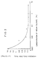
- Fig. 2 shows the hydrogen gas generated amount with respect to the indium sulfate concentration.
- Fig. 3 shows current-potential curves at ordinary temperature in the potassium hydroxide solution.
- Fig. 4 shows current-potential curves at ordinary temperature in the potassium hydroxide solution in which zinc oxide is dissolved up to approximate saturation.
- Fig. 5 shows the hydrogen gas generation amount with respect to days passed.
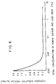
- Fig. 6 shows the hydrogen gas generation amount with respect to the indium sulfate concentration.
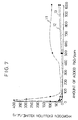
- Fig. 7 is a figure showing the generation amount of hydrogen gas with respect to the amount of lead monoxide added into the electrolyte solution of the present invention.
- Fig. 8 is a figure showing the generation amount of hydrogen gas with respect to the amount of lead monoxide added into the electrolyte solution.
- Fig. 9 shows the hydrogen generation amount with respect to the amount of water added per 1 mg of zinc when the electrolyte solution of the potassium hydroxide type is used.
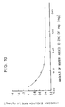
- Fig. 10 shows the hydrogen generation amount with respect to the amount of water added per 1 mg of zinc when the electrolyte solution of the sodium hydroxide type is used.
- Fig. 11 shows the generation amount of hydrogen gas with respect to days passed when the inhibitor of the present invention is added to the plated copper plate.
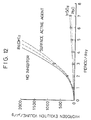
- Fig. 12 shows the generation amount of hydrogen gas with respect to days passed when the inhibitor of the present invention is added to the non-plated copper plate.
- Fig. 13 shows the change in the self-discharge rate with respect to the inhibitor concentration.
- Fig. 14 shows the change in the self-discharge rate after 50 % depth discharge with respect to the inhibitor concentration.
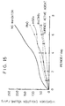
- Fig. 15 shows the generation amount of hydrogen gas with respect to days passed when the inhibitor of the present invention is added to the plated copper plate.
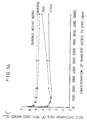
- Fig. 16 shows the generation amount of hydrogen gas with respect to days passed when the inhibitor of the present invention is added to the non-plated copper plate.
- Fig. 17 shows the change in the self-discharge rate with respect to the inhibitor concentration.
- Fig. 18 shows the change in the self-discharge rate after 50 % depth discharge with respect to the inhibitor concentration.
- Fig. 19 is a figure showing the hydrogen gas generation amount with respect to barium hydroxide.
- the electrolyte solution was prepared such that by making, a solution in which potassium hydroxide was 30 % by weight and zinc oxide was added up to approximate saturation in the case of the potassium hydroxide type, or a solution in which sodium hydroxide was 25 % by weight and zinc oxide was added up to approximate saturation in the case of the sodium hydroxide type, as a base, an indium compound was added thereto.
- Indium sulfate made by Nihon Kagaku Sangyo Co., Ltd., indium sulfamate 35 % solution also made by Nihon Kagaku Sangyo Co., Ltd., indium chloride made by Wako Pure Chemical Industries., Ltd., and indium cyanide made by Ito Phamaceutical Co., Ltd. were used.
- the adding amount of the indium compound was 1000 ppm with respect to the electrolyte solution. Results are shown in the hydrogen generation amount in Table 1. The unit is ⁇ L/g/day.
- Fig. 1 the hydrogen gas generation amount with respect to the number of test days of the samples using the electrolyte solution of the potassium hydroxide series, is shown. It has been found that in the case of no addition of the indium compound shown in 1 in the figure, the hydrogen generation amount increases exponential functionally with respect to the number of test days. It is understood that in the case of addition of the indium sulfate in 2 in the figure which is the indium compound of the present invention, the generation of hydrogen gas is suppressed. In the case of addition of the indium oxide in 3 in the figure, the hydrogen gas generation in the former half is much. This is considered to be due to the fact that the solubility of indium oxide is bad, the supply of indium ion to the electrolyte solution is not sufficient, and a long time is required to coat the surfaces of zinc and copper.
- a positive electrode can Into a positive electrode can were added a part of an electrolyte solution and 116 mg of a pellet (silver oxide content of 98 %) which was molded by adding a combined agent into silver oxide, and a separator of polyethylene and a separator of cellophane were set place. Next, a gasket of nylon was pushed and fitted into the positive electrode can, an impregnating agent, a gelling agent, 30 mg of zinc powder, an inhibitor and the like were added, the remainder of the electrolyte solution was added dropwise, and then a negative electrode can was set place to perform sealing to manufacture 100 pieces for every kind of button type silver oxide batteries. The same zinc as in Embodiment 1 and the electrolyte solution in Table 1 were used, and the battery size was made as the SR621 type.
- the adding amount of indium was 1000 ppm with respect to the amount of zinc.
- Results are shown in the discharge index in Table 1. Discharge characteristics were measured using a resistance of 200 ⁇ by means of the direct current method when the electrolyte solution was the potassium hydroxide series or the pulse method when it was the sodium hydroxide. In any case, no addition of the inhibitor was regarded to have a discharge index of 100. As understood also from the results, it has been found that the indium compound of the present invention is effective also in the discharge characteristics.
- a button type silver oxide battery was manufactured. Ten pieces of the manufactured silver oxide batteries were put into a vessel made of glass filled with liquid paraffin in a high temperature tank, a collecting tube having graduations at an upper portion was attached, and the amount of generated hydrogen gas was measured. This state was maintained at 60 °C for 20 days said which as to correspond to a term of about 1 year, and the hydrogen gas generation amount after 20 days was investigated. With respect to the inhibitor, the test was performed using indium sulfate at a concentration of 10 ppm to 5 % with respect to the weight of zinc. Evaluation results are shown in Fig. 2. According to the figure, it is understood that the inhibitor effectively works at 100 ppm to 1 %.
- the gasket of polypropylene was returned to one made of nylon, and a button type silver oxide battery was manufactured in a range of an indium sulfate concentration of 100 ppm to 1 % in which the gas generation was less.
- Ten pieces of the manufactured batteries were put into a vessel made of glass filled with liquid paraffin in a high temperature tank maintained at 25 °C in the same manner, and a collecting tube for generating hydrogen gas was attached to the upper portion. Hydrogen gas generation, expansion of the can and liquid leakage were not observed after 20 days at 60 °C.
- indium sulfate it was effective in the concentration of 100 ppm to 1 % with respect to zinc, however, the same effect was observed also in the case of other indium compounds by adjusting the mole number and determining the concentration range.
- Embodiment 1 In the actual trial production of batteries, there is given a value smaller than the hydrogen gas generation amount in the experiment in Embodiment 1. In respect to this fact, it is considered that the copper piece used in Embodiment 1 is different from a structure of an actual collector, and a part of generated hydrogen gas has been consumed by the reduction of silver oxide and the like.
- the method in Embodiment 1 is different in the amount order of hydrogen gas generation, but it is sufficient as a method for observing substituted characteristics for predicting hydrogen generation in an actual battery.
- the current-potential curve during deposition of indium was determined.
- the potential was scanned from the plus side to the minus side at a speed of 100 mV/second.
- the current for each potential represents the reaction at the electrode, and for example, if the reduction reaction such as deposition of indium and generation of hydrogen gas occurs, a current caused thereby flows.
- Results are shown in Fig. 3. 1 in the figure is a case where indium sulfamate was added to the electrolyte solution by 0.1 mol/L, in this case, the current began to flow from the vicinity of -1.1 V with respect to the reference electrode, and indium was deposited accompanying hydrogen generation.
- 2 is a current-potential curve of a case in which 0.1 mol/L of potassium tartarate was added to the electrolyte solution, and then 0.1 mol/L of indium sulfamate was added. It was found that indium was deposited at the vicinity of -1.4 V, and hydrogen was generated under the vicinity of -2.0 V. This is considered such that since indium having a high hydrogen overvoltage was deposited on the electrode surface, the potential for hydrogen generation was shifted toward the minus side.
- Fig. 3 In 3 in Fig. 3 is shown a current-potential curve of a case where indium sulfamate was added to the electrolyte solution by 0.1 mol/L, and then 0.1 mol/L of potassium tartarate was added.
- a small peak probably considered as indium is observed in the vicinity of -1.4 V in the figure, however, indium is deposited accompanying hydrogen generation from the vicinity of -1.1 V with respect to the reference electrode in the same manner as the case of no addition of potassium tartarate, and the effect of addition of the complexing agent becomes small.
- This also can be said for other indium compounds and complexing agents, and in order to immediately form the complex ion of indium and prevent precipitation, it is necessary to dissolve the complexing agent previously in the electrolyte solution.
- the electrode potential of zinc was -1.509 V with respect to the reference electrode. It just corresponds to a potential at which only indium or an alloy having a large amount of indium is deposited in a solution containing a complexing agent. Namely, indium or the alloy having a large amount of indium is deposited on zinc and the collector contacting with zinc, which prevents zinc and the collector from corrosion and dissolution.
- the electrolyte solution was prepared such that by making a solution in which potassium hydroxide was 30 % by weight and zinc oxide was added up to approximate saturation in the case of the potassium hydroxide series, or a solution in which sodium hydroxide was 25 % by weight and zinc oxide was added up to approximate saturation in the case of the sodium hydroxide series, as a base, and a complexing agent and an indium compound were added thereto.
- the adding amount of the indium compound was 1000 ppm with respect to the electrolyte solution, and the adding amount of the complexing agent was made 2-fold excessive in a mole ratio of indium ion.
- results in the case where the indium compound was added without adding of the complexing agent are shown in Table 2.
- the hydrogen gas generation amount is shown in Table 3 in the case where the complexing agent was added.
- the hydrogen generation index is the value in which the hydrogen generation amount in the test using the same electrolyte solution except for the complexing agent is regarded as 100.
- a positive electrode can Into a positive electrode can ware added a part of an electrolyte solution and 116 mg of a pellet (silver oxide content of 98 %) which was molded by putting a combined agent into silver oxide, and a separator of polyethylene and a separator of cellophane were set place. Next, a gasket of nylon was pushed and fitted into the positive electrode can, an impregnating agent, a gelling agent, 30 mg of zinc powder, an inhibitor and the like were added, the remainder of the electrolyte solution was added dropwise, and then a negative electrode can was set place to perform sealing to manufacture 100 pieces for every kind of button type silver oxide batteries. The same zinc as in Embodiment 6 and the electrolyte solution in Table 2 were used, and the battery size was made as the SR621 type.
- the adding amount of indium was made 1000 ppm with respect to the amount of zinc, and the adding amount of the complexing agent was made 2-fold in a mole ratio of indium ion.
- Discharge characteristics were measured using a resistance of 200 ⁇ by means of the direct current method when the electrolyte solution was the potassium hydroxide series or the pulse method when it was the sodium hydroxide series.
- no addition of the complexing agent was regarded to have a discharge index of 100. Results are shown with the right discharge index in Table 2. The effect of glycine is rather small, however, the effect was observed for all of the tested complexing agents.
- Embodiment 8-11 the effect in the case in which two or more species selected form the indium compound, the tin compound containing tetravalent tin and lead oxide are used as the inhibitor of the present invention will be explained. ⁇ Embodiment 8 ⁇
- the electrolyte solution was prepared such that by adding a solution in which potassium hydroxide was 30 % by weight and zinc oxide was added up to approximate saturation in the case of the potassium hydroxide series, or a solution in which sodium hydroxide was 25 % by weight and zinc oxide was added up to approximate saturation in the case of the sodium hydroxide series, as a base, and compounds selected front indium sulfate, indium sulfamate, sodium stannate and lead oxide were added thereto.
- lead oxide provides a relatively large amount of hydrogen generation. This is considered to be due to the fact that when lead is deposited, needle-like crystals are generated to become impossible to homogeneously coat the surfaces of zinc and the collector. From a viewpoint of the combination, it is understood that the combination of the compound of indium and lead oxide is especially good, which suppress the hydrogen generation, and the discharge characteristics are improved.
- a positive electrode Into a positive electrode can were added a part of an electrolyte solution and 116 mg of a pellet (silver oxide content of 98 %) which was molded by adding a combined agent into silver oxide, and a separator of polyethylene and a separator of cellophane were set place. Next, a gasket of nylon was pushed and fitted into the positive electrode can, an impregnating agent, a gelling agent, and 30 mg of zinc powder were added, the remainder of the electrolyte solution added with the compound selected from indium sulfate, indium sulfamate, sodium stannate and lead oxide was added dropwise, and then a negative electrode can was set place to perform sealing to manufacture 100 pieces for every kind of button type silver oxide batteries.
- one in which lead oxide is added has a discharge index superior to those of others owing to the improvement in the electric contact by needle-like crystals. From a viewpoint of the combination, it is understood that the combination of the compound of indium and lead oxide is especially good, which suppress the hydrogen generation, and the discharge characteristics are improved. It can be supposed that indium suppresses the gas generation from zinc and the collector, and lead improves the discharge characteristics.
- a button type silver oxide battery was manufactured. Ten pieces of the manufactured silver oxide batteries were put into a vessel made of glass filled with liquid paraffin in a high temperature tank, a collecting tube having graduations at an upper portion was attached, and the amount of generated hydrogen gas was measured. In this state, it was maintained at 60 °C for 20 days, which is so as said to correspond to a term of about 1 year, and the hydrogen gas generation amount after 20 days was investigated. With respect to the adding compound, the test was performed using indium sulfate and lead oxide in a weight ratio of 1:1 at a concentration of 10 ppm to 5 % in total with respect to the weight of zinc. Evaluation results are shown in Fig. 6. According to the figure, it is understood that the adding compound effectively works at 50 ppm to 1 %.
- the gasket of polypropylene was returned to one made of nylon, and a button type silver oxide battery was manufactured in a range of concentration of 50 ppm to 1 % using indium sulfate and lead oxide in which the gas generation was less.
- Ten pieces of the manufactured batteries were put in a vessel made of glass filled with liquid paraffin in a high temperature tank maintained at 60 °C in the same manner, and a collecting tube for generating hydrogen gas was attached to the upper portion. Hydrogen gas generation, expansion of the can and liquid leakage were not observed after 20 days at 60 °C.
- Indium sulfate and lead oxide were effective for zinc at the concentration of 50 ppm to 1 %, however, the same effect was observed also in the case of other combinations of compounds by adjusting the mole number and determining the concentration range.
- Embodiment 8 In the actual trial production of batteries, there is given a value smaller than the hydrogen gas generation amount in the experiment in Embodiment 8. That is, it is considered that the copper piece used in Embodiment 8 is different from a structure of an actual collector, a part of generated hydrogen gas has been consumed by the reduction of silver oxide, and the like.
- the method in Embodiment 8 is different in the amount order of hydrogen gas generation, but it is sufficient as a method for observing substituted characteristics for predicting hydrogen generation in an actual battery.
- a button type silver oxide battery was manufactured.
- tow kinds of electrolyte solutions indium sulfate and lead oxide of 50 ppm with respect to zinc were prepared, and they were added by dividing into two times with changing the order.
- the test was performed at 60 °C for 20 days in the same manner as Embodiment 9.
- the hydrogen generation amount was 0.10 ⁇ L/g/day for one in which indium sulfate was added previously, and it was 0.15 ⁇ L/g/day for one in which lead oxide was added previously.
- indium sulfate was added previously has a larger effect for the hydrogen gas generation.
- the electrolyte solution was prepared such that by making a solution in which potassium hydroxide was 30 % by weight and zinc oxide was added up to approximate saturation in the case of the potassium hydroxide series, or a solution in which sodium hydroxide was 25 % by weight and zinc oxide was added up to approximate saturation in the case of the sodium hydroxide series as a base, and the inhibitor of the present invention such as lead monoxide and the like was added thereto.
- Fig. 7. 1 in the figure is a case where zinc powder added with 200 ppm of indium was used, and there is an effect of suppressing hydrogen generation at an adding amount of lead monoxide of about 100-400 ppm.
- 2 is a case where zinc powder added with 500 ppm of indium was used, and there is an effect of suppressing hydrogen generation at an adding amount of lead monoxide of not less than 10 ppm.
- 3 is a case where zinc powder added with 1800 ppm of indium was used, and there is an effect in a concentration range equivalent to that in 2.
- indium is added in a high concentration in such a manner, the effect at an adding amount of lead monoxide of not more than 100 ppm is remarkable, and it is possible to reduce the adding amount of lead as an environmental pollution substance.
- a positive electrode Into a positive electrode can were added a part of an electrolyte solution and 116 mg of a pellet (silver oxide content of 98 %) which was molded by adding a combined agent into silver oxide, and a separator of polyethylene and a separator of cellophane were set place. Next, a gasket of nylon was pushed and fitted into the positive electrode can, an impregnating agent, a gelling agent, 30 mg of zinc powder, an inhibitor and the like were added, the remainder of the electrolyte solution was added dropwise, and then a negative electrode can was set place to perform sealing to manufacture 100 pieces for every kind of button type silver oxide batteries. The battery size was made as SR621 type. The electrolyte solution was made again so as to allow the adding amount of lead monoxide to be an amount with respect to the zinc amount. They were stored at 60 °C for 20 days, and results of measurement of the self-discharge rate are shown in Table 6.
- the reduction in the battery capacity is suppressed by adding 100-1000 ppm of lead monoxide in the case of the zinc powder added with 500 ppm of indium, or 10-1000 ppm of lead monoxide in the case of the zinc powder added with 1800 ppm of indium.
- the decrease in the battery capacity by the addition of lead monoxide at the high concentration is considered to be due to the fact that needle-like crystals of lead grew on account of excessive addition, and a short circuit might be caused.
- a button type silver oxide battery was manufactured in the same manner as Embodiment 13 except that a gasket of polypropylene specially prepared for allowing hydrogen to penetrate was used. Ten pieces of the manufactured silver oxide batteries were put into a vessel made of glass filled with liquid paraffin in a high temperature tank, a collecting tube having graduations at an upper portion was attached, and the amount of generated hydrogen gas was measured. In this state, it was maintained at 60 °C for 20 days, which is said to correspond to a term of about 1 year, and the hydrogen gas generation amount after 20 days was investigated. Results are shown in Table 6.
- the hydrogen generation is mild and the self-discharge is also less in the case of the sodium hydroxide series as compared with the potassium hydroxide series with respect to the electrolyte solution.
- Embodiment 12 is different in the amount order of hydrogen gas generation, but it is sufficient as a method for observing substituted characteristics for predicting hydrogen generation in an actual battery.
- zinc powder one containing 100 ppm of gallium manufactured by the atomization method, 200 ppm of indium, 500 ppm of lead and 450 ppm of aluminum, and further containing 5 ppm of iron was used.
- concentration of iron in the zinc powder was adjusted by performing iron removal by means of a magnet. The concentration after the iron removal was confirmed by the atomic absorption method.
- the hydrogen generation test was performed such that into a specially prepared test tube having a volume of 25 ml and graduated to know the gas generation amount were put beforehand 2 g of zinc powder and a copper piece as the same material as a collector having an area of 0.6 cm2 and a thickness of 0.1 mm, an electrolyte solution to be tested was added thereto to heat to 60 °C, and the volume of generated hydrogen gas was measured for 7 days. The number of repetition of the test was 10, and an average value thereof was used as a result.
- the electrolyte solution was prepared such that by making a solution in which potassium hydroxide was 30 % by weight and zinc oxide was added up to approximate saturation in the case of the potassium hydroxide series, or a solution in which sodium hydroxide was 25 % by weight and zinc oxide was added up to approximate saturation in the case of the sodium hydroxide series, as a base lead monoxide or the like was added thereto as the inhibitor.
- the concentration of iron in the zinc powder and the generation amount of hydrogen gas with respect to the adding amount of the inhibitor are shown in Table 7.
- the adding amount of the inhibitor is shown by ppm with respect to the electrolyte solution. Results are also shown in the hydrogen generation amount in Table 7.
- Fig. 8. 1 in the figure is a case in which the zinc powder having a concentration of iron of 5 ppm was used, and the hydrogen generation amount is generally large as compared with other two ones.
- 2 is a case in which the zinc powder having a concentration of iron of 4 ppm was used, and there is an effect of suppressing hydrogen generation at an adding amount of lead monoxide of not less than 10 ppm.
- 3 is a case in which the zinc powder having a concentration of iron of 2 ppm was used, and there is an effect in a concentration range equivalent to that of 2.
- iron as an impurity was made not more than 4 ppm, the effect of the adding amount of lead monoxide of not more than 100 ppm is evident, and it is possible to reduce the adding amount of lead as an environmental pollution substance.
- a positive electrode can Into a positive electrode can were added a part of an electrolyte solution and 116 mg of a pellet (silver oxide content of 98 %) which was molded by adding a combined agent into silver oxide, and a separator of polyethylene and a separator of cellophane were set place. Next, a gasket of nylon was pushed and fitted into the positive electrode can, an impregnating agent, a gelling agent, 30 mg of zinc powder, an inhibitor and the like were added, the remainder of the electrolyte solution was added dropwise, and then a negative electrode can was set place to perform sealing to manufacture 100 pieces for every kind of button type silver oxide batteries. The battery size made as SR621 type. The electrolyte solution was made again so that the adding amount of lead monoxide to be an amount with respect to the zinc amount.
- the self-discharge rate can be suppressed to be not more than 4 % by adding 10-1000 ppm of lead monoxide in the battery using the zinc powder having iron of not more than 4 ppm.
- the decrease in the battery capacity by the addition of lead monoxide at the high concentration is considered if it is due to the fact that needle-like crystals of lead grew on account of excessive addition, and a short circuit might be caused.
- a button type silver oxide battery was manufactured in the same manner as Embodiment 16 except that a specially prepared gasket of polypropylene for allowing hydrogen to penetrate was used. Ten pieces of the manufactured silver oxide batteries were put into vessel made of glass filled with liquid paraffin in a high temperature tank, a collecting tube having graduations at the upper portion was attached, and the amount of generated hydrogen gas was measured. This state was maintained at 60 °C for 20 days which is said to correspond to a term of about 1 year, and the hydrogen gas generation amount after 20 days was investigated. Results are shown in Table 8.
- the hydrogen generation is mild and the self-discharge is also less in the case of the sodium hydroxide series as compared with the potassium hydroxide series with respect to the electrolyte solution.
- Embodiment 15 is different in the amount of order of hydrogen gas generation, but it is sufficient as a method for observing substituted characteristics for predicting hydrogen generation in an actual battery.
- impurities such as nickel, cobalt, antimony and the like
- the negative electrode active material such as zinc and the like in which hydrogen generation is large, a homogeneous film is difficult to be formed due to the hydrogen generation which occurs as a competitive reaction against lead deposition onto the surface, and the effect of lead deposition becomes small.
- a positive electrode Into a positive electrode can were added a part of an electrolyte solution and a pellet (silver oxide content of 98 %) which was molded by putting a combined agent into silver oxide, and a separator of polyethylene and a separator of cellophane were set place.
- a gasket of specially prepared polypropylene for allowing hydrogen to penetrate was pushed and fitted into the positive electrode can, an impregnating agent, a gelling agent, zinc powder, an inhibitor and the like were added, the remainder of the electrolyte solution was added dropwise, and then a negative electrode can was set place to perform sealing to manufacture a button type silver oxide battery.
- the electrolyte solution was prepared such that by making a solution in which potassium hydroxide was 30 % by weight and zinc oxide was added up to approximate saturation in the case of the potassium hydroxide series, or a solution in which sodium hydroxide was 25 % by weight and zinc oxide was added up to approximate saturation in the case of the sodium hydroxide series, as a base, and the inhibitor was optionally added thereto. When the inhibitor is added, its amount was made as 1000 ppm with respect to the zinc weight, and it was dissolved in the electrolyte solution.
- the size of the coin or button silver oxide battery manufactured and evaluated, the content of metal in the zinc powder used, the electrolyte solution, the moisture amount, the inhibitor added, and the hydrogen generation amount and the self-discharge rate after the storage at 60 °C for 20 days are shown in Table 9 and Table 10.
- the weight for zinc was expressed by ppm.
- the moisture amount was represented by how much mg of water was contained with respect to 1 mg of zinc.
- the unit for the hydrogen generation amount is ⁇ /g/day, the hydrogen generation amount per one day with respect to the zinc amount is shown at the right of each of the columns for 60 °C for 20 days and ordinary temperature for 1 year in the table, and the unit for the self-discharge rate is shown by %.
- In-sulfate indicates indium sulfate
- In-sulfamate indicates indium sulfamate
- PbO indicates lead oxide.
- Embodiment 18 In order to know whether or not the storage at 60 °C for 20 days in Embodiment 18 corresponds to 1 year at ordinary temperature, a test for 1 year was actually performed.
- Embodiment 18 The gasket used in Embodiment 18 was exchanged into one made of nylon being used in ordinary production of silver oxide batteries, and coin or button silver oxide batteries were manufactured in the same manner. Ten pieces of the manufactured silver oxide batteries were put into a vessel made of glass filled with liquid paraffin in a high temperature tank maintained at 25 °C, and a collecting tube for generating hydrogen gas was attached at the upper portion. This state was maintained for 1 year, and the hydrogen generation amount and the self-discharge rate after 1 year were investigated. The measurement method was the same as that in Embodiment 18. Results of the hydrogen generation amount and the self-discharge rate are shown at the right ends in Table 9 and Table 10.
- the electrolyte solution in the case of the potassium hydroxide series, one in which zinc oxide was added to potassium hydroxide up to approximate saturation was used.
- the amount of the electrolyte solution to be added per 1 mg of zinc was changed from 0.37 to 0.96 mg which was from 0.25 to 0.65 mg as calculated into the amount of water, using zinc containing 500 ppm of each of indium, lead and bismuth and a gasket of polypropylene in the same manner as Embodiment 18, a silver oxide battery of the SR626 size was made, and the storage test was performed at 60 °C for 20 days.
- the hydrogen generation amount with respect to the added amount of water is shown in Fig. 9.
- the hydrogen generation amount indicates an amount generated from 1 g of zinc per one day, and the unit is ⁇ L/g/day. According to the result, it is understood that when the amount of water is not less than 0.31 mg, the hydrogen generation amount is lowered to not more than 0.54 ⁇ L/g/day (0.03 ⁇ L/g/day as calculated into a value at ordinary temperature). In addition, when the amount of water was not less than 0.57 mg, the occurrence of liquid leakage was observed.
- the amount of water to be added per 1 mg of zinc is 0.31-0.57 mg when the electrolyte solution is the potassium hydroxide series, and it is 0.32-0.59 mg in the case of sodium hydroxide.
- the storage test at ordinary temperature for 1 year was performed and tried using the method in Embodiment 19.
- the electrolyte solution was added as that the amount of water to be added per 1 mg of zinc became 0.31, 0.44 and 0.57 mg.
- the electrolyte solution was added so that the amount of water became 0.32, 0.45 and 0.59 mg.
- the gasket was changed into nylon in the same manner as Embodiment 20, and 10 pieces of silver oxide batteries were manufactured, respectively. According to the results of the storage test at ordinary temperature for 1 year for the manufactured silver oxide batteries, there was no hydrogen generation, the self-discharge rates were also not more than 4 % for all ones, and it has been found that there is no practical problem.
- the electrolyte solution was prepared such that by making a solution in which potassium hydroxide was 30 % by weight and zinc oxide was added up to approximate saturation in the case of the potassium hydroxide series, or a solution in which sodium hydroxide was 25 % by weight and zinc oxide was added up to approximate saturation in the case of the sodium hydroxide series as a base, and an inhibitor was optionally added thereto.
- the hydrogen generation from zinc was measured by the combination of a copper plate coated by the electric plating and the substitution plating and the inhibitor.
- the plating treatment is shown hereinafter.
- the concentration of the inhibitor is shown by a value with respect to the electrolyte solution.
- the surfactant of the fluorocarbon(carbon fluoride)-polyoxyethylene (POE) series one having a carbon number of fluorocarbon of 10 and a polymerization degree of POE of 50 was used. Usually, the same effect can be obtained if the one having a carbon number of fluorocarbon of 4-20 and a polymerization degree of POE of 30-100 is used.
- the hydrogen gas generation amount decreases to about 1/3 to 1/2, and it is understood that there is an effect in relation to suppression of the hydrogen gas generation.
- the difference due to the plating or the inhibitor is not presented so much.
- the hydrogen gas generation amount with respect to the number of test days is shown in Fig. 11 as for the measurement result of the case using indium plated copper plates.
- the indium compound only indium sulfate is shown in the figure.
- the hydrogen gas generation is in a low level similar as the Embodiments, and there is not too much bad effect even when a plurality of inhibitors are used.
- a positive electrode can Into a positive electrode can were added a part of an electrolyte solution and 116 mg of a pellet (silver oxide content of 98 %) was molded by putting a combined agent into which silver oxide, and a separator of polyethylene and a separator of cellophane were set place. Next, a gasket of nylon was pushed and fitted into the positive electrode can, an impregnating agent, a gelling agent, and 30 mg of zinc powder were added, the remainder of the electrolyte solution optionally added with an inhibitor was added dropwise, and then a negative electrode can was set place to perform sealing to manufacture 100 pieces for every kind of button type silver oxide batteries.
- the type and the film thickness of plating onto the negative electrode can, the type and the concentration of the added inhibitor, the closed circuit voltage and the self-discharge rate are shown in Tables 15 and 16.
- the inhibitor concentration in the table indicates a value with respect to the zinc weight.
- the measurement of the self-discharge rate was performed after maintaining it at 60 °C for 20 days, which is said to correspond to 1 year.
- the self-discharge rate after partial discharge was measured by being left at 60 °C for 20 days after 50 % depth discharge (partial discharge).
- the closed circuit voltage was measured at -10 °C before discharge and after partial discharge.
- the plating onto the negative electrode can was performed in the same manner as Embodiment 22, and results for each film thickness of 0.3 ⁇ m have been shown. There was little difference in the result even when those having a film thickness of 0.1-1 ⁇ m were used.
- the self-discharge rate after lapse of corresponding 1 year and the self-discharge rate after partial discharge with respect to the inhibitor concentration were measured.
- Results are shown in Figs. 13 and 14. Provided that the practical range is not more than about 3 % of the self-discharge rate, it has been found that the effect is provided for indium sulfate of 50-5000 ppm, for lead monoxide of 20-5000 ppm, for barium hydroxide of not less than 50 ppm, and for the fluorocarbon-polyoxyethylene type surfactant of not less than 100 ppm as the concentration with respect to zinc. With respect to the self-discharge rate after 50 % depth discharge, the effect was provided for indium sulfate of 50-5000 ppm, and for lead monoxide of 20-5000 ppm.
- Embodiments 25-29 the effect of the case combined each techniques will be explained.
- the evaluation was made using combinations in which the surfactants were changed.
- the evaluation was made also by changing the type of zinc.
- the electrolyte solution was prepared such that by making a solution in which potassium hydroxide was 30 % by weight and zinc oxide was added up to approximate saturation in the case of the potassium hydroxide type, or a solution in which sodium hydroxide was 25 % by weight and zinc oxide was added up to approximate saturation in the case of the sodium hydroxide type, as a haze and an inhibitor was optionally added thereto.
- the hydrogen generation from zinc was measured by the combination of a copper plate coated by the electric plating and the substitution plating and the inhibitor.
- the plating treatment is shown hereinafter.
- electric plating plating bath indium sulfate 60 g/l, sodium sulfate 10 g/l, 25 °C plating film thickness: 0.3 ⁇ m
- electric plating plating bath potassium stannate 100 g/l, potassium hydroxide 15 g/l, potassium acetate 5 g/l, 70 °C planting film thickness: 0.3 ⁇ m
- Polyoxyethylene alkylamide is the one (represented by POERA in the table and the figure), in which two polyoxyethylenes (POE) are bonded to the alkyl group at nitrogen through amide bond.
- POE polyoxyethylenes
- the one having a carbon number of the alkyl group of 11 and a polymerization degree of POE of 15 was used.
- the one having a carbon number of the alkyl group of 3-30 and a polymerization degree of POE of 2-50 is used, the same effect is obtained.
- the hydrogen gas generation amount decreases to about 1/3 to 1/2, and it is understood that there is an effect in relation to suppression of the hydrogen gas generation.
- the difference due to the plating or the inhibitor is not presented so much.
- the hydrogen gas generation amount with respect to the number of test days is shown in Fig. 15 as the measurement result of the case using indium plated copper plates.
- the indium compound only indium sulfate is shown in the figure.
- the hydrogen gas generation is at a low level in the same manner as Example, and there is not too much bad effect even when a plurality of inhibitors are used. Especially, the hydrogen gas generation is less in the one in which barium hydroxide and polyoxyethylene alkylamide are simultaneously added.
- a positive electrode can Into a positive electrode can were added a part of an electrolyte solution and 116 mg of a pellet (silver oxide content of 98 %) in which silver oxide was added and molded with a combined agent, and a separator of polyethylene and a separator of cellophane were placed. Next, a gasket of nylon was pushed and fitted into the positive electrode can. and filling with an impregnating agent, a gelling agent, and 30 mg of zinc powder, the remainder of the electrolyte solution optionally added with an inhibitor was added dropwise, and then a negative electrode can was placed to perform sealing to manufacture 100 pieces for each kind of button type silver oxide batteries.
- the zinc powder was used one containing 130 ppm of bismuth, 500 ppm of indium and 30 ppm of aluminum manufactured by atomization.
- the type and the film thickness of plating onto the negative electrode can, the type and the concentration of the added inhibitor, the closed circuit voltage and the self-discharge rate are shown in Tables 21 and 22.
- the inhibitor concentration in the table indicates a value with respect to the zinc weight.
- the measurement of the self-discharge rate was performed after maintaining at 60 °C for 20 days said to be equivalent to 1 year.
- the self-discharge rate after partial discharge was measured by being left at 60 °C for 20 days after 50 % depth discharge (partial discharge).
- the closed circuit voltage was measured at -10 °C before discharge and after partial discharge.
- the plating onto the negative electrode can was performed in the same manner as Example 25, and results for each film thickness of 0.3 ⁇ m have been shown. There was little difference in the result even when those having a film thickness of 0.1-1 ⁇ m were used.
- the self-discharge rate corresponding to the one after 1 year and the self-discharge rate after partial discharge with respect to the inhibitor concentration were measured.
- Results are shown in Figs. 17 and 18. Provided that the practical range is not more than about 3 % of the self-discharge rate, according to Fig. 17, it has been found to be effective for indium sulfate of 50-5000 ppm, for lead monoxide of 20-5000 ppm, for barium hydroxide of not less than 50 ppm, and for polyoxyethylene alkylamide of not less than 5 ppm as the concentration with respect to zinc.
- Trial production of batteries was performed in the same manner as Example 27 by changing the zinc composition. Using an electrolyte solution of the KOH type and plating of indium onto a negative electrode can, and as the inhibitor, each 1000 ppm of indium sulfate, lead monoxide, barium hydroxide and polyoxyethylene alkylamide with respect to zinc was added. Results are shown in Table 23.
- the self-discharge rate is included in a practical range of not more than 3 % in the compositions of additives defined in claims. In order to lower the self-discharge rate, it is desirable to form an alloy of several species.
- the effect of the present invention was confirmed in a form of a hydrogen gas generation test.
- the test was performed using a combination of zinc powder, a gelling agent of the present invention, barium hydroxide and a copper plate of the same material as that of the collector.
- a specially prepared test tube having a volume of 25 ml graduated to know the gas generation amount was added 2 g of zinc powder containing 500 ppm of each of bismuth, indium and lead manufactured by the atomization method, and an electrolyte solution to be tested was added thereto and heated to 60 °C , and the volume of generated hydrogen gas was measured for 7 days.
- the gelling agent was added by 1.5 % with respect to zinc.
- the electrolyte solution was prepared by providing a base solution in which potassium hydroxide was 30 % by weight and zinc oxide was added up to approximate saturation in the case of the potassium hydroxide type, or a base solution in which sodium hydroxide was 25 % by weight and zinc oxide was added up to approximate saturation in the case of the sodium hydroxide type, and barium hydroxide was added thereto.
- Barium hydroxide was made by Wako Pure Chemical Industries., Ltd.
- CMC was No. 1260 and No. 1380 made by Daicel Chemical Industries, Ltd.
- PAS was a reagent made by Wako Pure Chemical Industries., Ltd. and Rheogic 250H made by Nihon Pure Chemicals Co., Ltd.
- the added amount of barium hydroxide was 0-50000 ppm with respect to the electrolyte solution. Results are shown in the hydrogen generation amount in Table 24.
- the unit is ⁇ l/g/day. According to the result in Table 24, it is understood that one added with barium hydroxide has a small hydrogen generation amount irrespective to comparison in the gelling agent type, the zinc powder simple substance and the zinc powder + copper piece, and the electrolyte solution type, and the gas generation is small in PAS being a cross-linked type acrylic water-soluble resin with respect to the gelling agent type.
- a button type silver oxide battery of the SR621 size was prepared.
- As a negative electrode can the one in which a collector was applied with tin plating of 0.1 ⁇ m was used.
- the zinc was the one used in Example 30, Rheogic 250H as a cross-linked type acrylic water-soluble resin for a gelling agent, and a potassium hydroxide 30 % by weight solution or a sodium hydroxide 25 % by weight solution added with zinc oxide up to approximate saturation respectively for an electrolyte solution.
- the adding amount of the gelling agent was 1.5 % with respect to zinc, and the adding amount of barium hydroxide was 0-50000 ppm with respect to zinc.
- the electric characteristics were measured by the direct current method with a load resistance of 200 ⁇ when the electrolyte solution was the potassium hydroxide type or the pulse method with a load resistance of 2 k ⁇ when it was the sodium hydroxide type. In either case, Conventional example was supposed to have a discharge index of 100. As being apparent also from the result, one in which the gelling agent of the present invention and the cross-linked type acrylic water-soluble resin were used and barium hydroxide was added had a good discharge performance as compared with Conventional example.
- a button type silver oxide battery was manufactured in the same manner.
- As a gelling agent 1.5 % of Rheogic 250H being a cross-linked type acrylic water-soluble resin was used with respect to zinc.
- Barium hydroxide had been tested with a concentration of 10 ppm to 5 % with respect to a weight of zinc.
- Ten pieced of the manufactured silver oxide batteries were placed in a vessel made of glass filled with liquid paraffin in a high temperature tank, a collecting tube having graduations at an upper portion was attached, and the amount of generated hydrogen was measured. This state was maintained at 60 °C for 20 days, and the hydrogen gas generation amount after 20 days was investigated.
- the gasket made of polypropylene was returned to one made of nylon, and a button type silver oxide battery was manufactured in a range of barium hydroxide concentration of 100 ppm to 1 % which had less gas generation.
- Ten pieces of the manufactured batteries were placed in a vessel made of glass filled with liquid paraffin in a high temperature tank in the same manner, and a collecting tube for generating hydrogen gas was attached to an upper portion. Hydrogen gas generation, expansion of the battery can and liquid leakage were not observed after 20 days at 60 °C.
- the hydrogen gas generation amount in the actual battery has a value smaller than that of the hydrogen gas generation amount in the experiment in Example 30.
- the copper piece used in Example 30 is different from a structure of an actual collector, a part of generated hydrogen gas has been consumed by the reduction of silver oxide and the like.
- the method in Example 30 is different in the amount order of hydrogen gas generation, but it is sufficient as a method for observing substituted characteristics for predicting hydrogen generation in an actual battery.
- electrolyte solution a solution in which potassium hydroxide was 30 % by weight and zinc oxide was added up to approximate saturation in the case of the potassium hydroxide type, and a solution in which sodium hydroxide was 25 % by weight and zinc oxide was added up to approximate saturation in the case of the sodium hydroxide type.
- the hydrogen generation from zinc and a copper piece coated with the electric plating and the substitution plating was measured. Four kinds of plating treatments onto the copper piece were performed. Conditions are shown hereinafter.
- contact plating A copper piece and zinc were placed into the following plating bath heated to 60 °C and left for 1 hour.
- plating bath KOH 30 %, ZnO saturation, indium sulfate 0-3000 ppm temperature: 60 °C plating film thickness: Adjustment was made depending on time. The thickness was determined from weights before and after the plating.
- contact plating A copper piece and zinc were placed into the following plating bath heated to 60 °C and left for 1 hour.
- plating bath KOH 30 %, ZnO saturation, lead oxide 0-3000 ppm temperature: 60 °C plating film thickness: Adjustment was made depending on time. The thickness was determined from weights before and after the plating.
- a copper piece was clamped in a net made of copper to allow a current to flow, and plating was performed. The copper piece was suitably moved so as not to make a portion not subjected to plating.
- plating bath zinc cyanide 70 g/l, sodium cyanide 50 g/l, sodium hydroxide 100 g/l, indium cyanide 0-3000 ppm temperature: 25 °C current density: 5
- A/dm2 plating film thickness Adjustment was made depending on time. The thickness was determined from weights before and after the plating.
- a copper piece was clamped in a net made of copper to allow a current to flow, and plating was performed. The copper piece was suitably moved so as not to make a portion not subjected to plating.
- plating bath zinc sulfate 240 g/l, sodium sulfate 30 g/l, sodium acetate 15 g/l, indium sulfate 0-3000 ppm temperature; 25 °C current density: 2
- A/dm2 plating film thickness Adjustment was made depending on time. The thickness was determined from weights before and after the plating.
- the hydrogen gas generation can be greatly suppressed as by adding a little amount of indium compound and lead oxide of about 10 ppm into the plating solution, and forming an alloy of the plating film as compared with no addition.
- indium compound and lead oxide of about 10 ppm into the plating solution, and forming an alloy of the plating film as compared with no addition.
- lead oxide in the case of addition of lead oxide in a high concentration, needle-like lead becomes deposited on the plating film, and the hydrogen gas generation is deteriorated.
- a positive electrode Into a positive electrode can were added a part of an electrolyte solution and placing thereinto 116 mg of a pellet (silver oxide content of 98 %) made by adding silver oxide being and molded with a combined agent, a separator of polyethylene and a separator of cellophane. Next, a gasket of nylon was pushed and fitted into the positive electrode can, an impregnating agent, a gelling agent, and 30 mg of zinc powder were added, the remainder of the electrolyte solution optionally added with an inhibitor was added dropwise, then a negative electrode can was placed and sealed to manufacture 100 pieces for each kind of button type silver oxide batteries.
- the zinc powder was used one containing 500 ppm of bismuth, 500 ppm of indium and 500 ppm of lead manufactured by atomization.
- the plating onto the negative electrode can was performed in the same manner as Example 32.
- the self-discharge rate with respect to the type of the plating onto the negative electrode can is shown in Tables 30 and 31.
- the measurement of the self-discharge rate was performed after maintaining 60 °C for 20 days as said to be equivalent to 1 year.
- Table 30 Self-discharge rate of cell with KOH electrolyte Experimental No. Condition of plating Self-discharge rate after 1 year storage % Kind of plating Additive 11 none - 5.8 12 Contact plating Indium sulfate 2.5 13 Contact plating PbO 2.8 14 Electroplating Indium cyanide 2.4 15 Electroplating Indium sulfate 2.4 Table 31 Self-discharge rate of cell with NaOH electrolyte Experimental No.
- Plating was performed for a negative electrode can having the SR521 size in which iron type foreign matters had adhered to the collector surface during press processing causing deficiency in gas generation.
- the deficiency in gas generation may become a cause of expansion and explosion when a battery is made, which can be confirmed by instant gas generation after adding an electrolyte solution and several zinc powder particles of about 100 ⁇ m to a concave surface at the copper side being the collector of the negative electrode can. This is due to the fact that zinc serves as an anode and iron having a lower hydrogen overvoltage serves as a cathode to generate hydrogen.
- the plating was performed by the substitution plating using a barrel. Conditions are described hereinafter.
- contact plating Using a barrel, a negative electrode can and a zinc piece were added into the following plating solution heated to 60 °C to perform plating.
- negative electrode can SR521 size, about 1000 pieces zinc piece: 3 x 3 x 0.1, about 1500 sheets plating solution: KOH 30 %, ZnO saturation, indium sulfate 0-300 ppm temperature: 60 °C time: 5, 15 and 30 minutes plating film thickness; The thickness was measured from weights of a copper plated added as a dummy before and after the plating.
- the film thickness against time was 0.041 ⁇ m for 5 minutes, 0.090 ⁇ m for 15 minutes, and 0.148 ⁇ m for 30 minutes. 100 pieces were picked out respectively, and the confirmation of gas generation was performed. As a result, the gas generation was found in 78 pieces out of 100 pieces in the case of those subjected to plating for 5 minutes. No gas generation was found in those subjected to plating for 15 and 30 minutes. According to this fact, it has been found that a plating thickness of about 0.1 ⁇ m has shielding effect for impurities.
- plating bath zinc cyanide 70 g/l, sodium cyanide 50 g/l, sodium hydroxide 100 g/l, indium cyanide 1000 ppm bath temperature; 25 °C Current density: 5 A/dm2 plating film thickness: Adjustment was made depending on time. The thickness (adjustment of the feed speed of the hoop material) was determined by embedding in a resin and taking a picture using an optical microscope.
- Negative electrode cans of 100 pieces were manufactured using each hoop material plated with a zinc alloy of each film thickness. The number of negative electrode cans in which the copper surface became exposed by processing was investigated. Results are shown in Table 7.
- the negative electrode cans of each film thickness were used to perform trial production of 100 pieces of batteries respectively with an NaOH type electrolyte solution in the same manner as Example 33.
- Table 32 Number of anode cap with generated pinhole and self-discharge rate Plating thickness ( ⁇ m) 1 2 3 4 7 10 Cell using analgamated zinc Number of anode cap with generated pinhole 8 3 0 0 0 0 0
- Initial capacity (mAh) 23.2 23.3 23.4 23.6 24.1 24.8 23.1 Capacity after 2 years storage (mAh) 21.2 21.7 22.0 22.7 23.0 23.8 22.6 Self-discharge rate (%/year) 4.4 3.5 2.9 1.9 2.1 2.0 1.1
- the initial capacity and the capacity corresponding to the one after 2 years are shown in Table 32.
- the plating of not more than 2 ⁇ m has a capacity smaller than that of the case in which direct plating was performed to the negative electrode can in Example 33, due to deficiency in the plating film by processing.
- the film thickness if 4 ⁇ m the capacity after 2 years becomes approximately the same as the one in which mercurated zinc is used. For example, when the battery is incorporated into a clock or watch, the battery service life is about 2 years.
- the zinc alloy plating thickness may be not less than 3 ⁇ m so as to have a thickness with which an aimed capacity is obtained in 2 years.
- a conventional battery in which zinc having a mercuration ratio of 10 % was used and a battery in which a 4 ⁇ m zinc-indium alloy was applied to a negative electrode can of the present invention by the same method as Example 35 using mercuryless zinc were actually installed in wristwatches, and a carrying test was performed to measure the number of days until the watch stopped. The test was done for each 10 pieces.
- Results are shown in Table 33.
- the number of days until the watch stopped was substantially the same, and coming off with the capacity not being lowered even in the case of no mercury.
- Example 35 it is apparent that when using as a standard a film thickness, in which the capacity after 2 years in the acceleration test becomes the same as that of the battery using mercurated zinc, it is possible to obtain a capacity equivalent to the one in which mercurated zinc is used also when used in an actual clock or watch.
- the zinc alloy plating thickness may be made to be not less than 3 ⁇ m so as to provide a thickness with which an aimed capacity is obtained in 2 years.
- the weight of zinc in the battery using mercurated zinc of an aimed capacity is W0
- the self-discharge rate / year is SD0
- the weight of zinc in the battery using mercuryless zinc to be designed is W0 (the same as mercurated zinc)
- the self-discharge rate is SD1
- the area of the collector is S
- the specific gravity of zinc is 7.13
- the clad material is plated with the zinc-indium alloy of not less than 3 ⁇ m, however, as shown in Examples 32 and 33, approximately the same effect
- the effect of the invention is not deteriorated even when elements which raise the hydrogen overvoltage of the zinc alloy such as bismuth, gallium, aluminum, calcium and the like exist in the zinc alloy layer containing indium or lead. Depending on the way of addition, further self-discharge suppressing effects can be expected.
- the alkaline battery in which the generation of hydrogen is suppressed without deteriorating battery characteristics. This is especially effective for coin type or button type alkaline batteries which require high performance but are sensitive to gas generation.
- the zinc alloy plating onto the collector of the present invention when it is used for minute discharge for clocks or watches or the like, it is possible to achieve a capacity which is equivalent to or not less than those of batteries in which mercurated zinc is used. Further, when clocks or watches carrying the alkaline batteries of the present invention are discarded, the environment is never polluted because mercury as an environmental pollution substance is not contained. When a applied product carrying the alkaline batteries are discarded, the environment is never polluted because mercury as an environmental pollution substance is not contained.
Landscapes
- Chemical & Material Sciences (AREA)
- Chemical Kinetics & Catalysis (AREA)
- Electrochemistry (AREA)
- General Chemical & Material Sciences (AREA)
- Engineering & Computer Science (AREA)
- Manufacturing & Machinery (AREA)
- Materials Engineering (AREA)
- Primary Cells (AREA)
- Battery Electrode And Active Subsutance (AREA)
- Cell Electrode Carriers And Collectors (AREA)
Abstract
This invention relates to an alkaline battery in which hydrogen gas evolution and deterioration of battery performance can be prevented by using a collector having an outermost layer coated with zinc or metal having a higher hydrogen overvoltage than that of zinc and adding an inhibitor selected from an indium compound, lead oxide, a hydroxide of alkaline earth metal and polyoxyethylen alkylamide to an electrolyte solution or a negative electrode active material.
According to the present invention, it is possible to manufacture an alkaline battery in which evolution of hydrogen can be restrained without involving deterioration of battery performances. Especially, the present invention is effective in a coin type and a button type battery which is sensitive to the evolution of gas and is required to have high performance.
Further, the inventive collector which is plated with zinc alloy more than 3 µ m in thickness and used for low drain such as watches can attain a capacity equivalent to or more than that of a battery using amalgamated zinc. Further, watches loaded with the inventive alkaline batteries which are discarded do not pollute the environment, as they do not include mercury to be a pollution material.
Description
- The present invention relates to an alkaline battery which uses mercuryless zinc powder as a negative electrode active material, and uses silver oxide, manganese dioxide, oxygen or the like as a positive electrode active material, and a clock or watch which uses the alkaline battery.
- There has been such a task that zinc powder used in the alkaline battery is corroded and dissolved by an electrolyte solution which is an alkali, and the generation of hydrogen gas and the self-discharge in battery performance accompanying therewith are large. In addition, a battery is formed by a collector such as copper or the like which contacts with zinc, and hydrogen gas has been also generated therefrom. In the prior art, as a countermeasure to prevent the above, it has been performed that zinc is mercurated with mercury having a high hydrogen overvoltage, or zinc oxide is added to an electrolyte solution up to approximate saturation.
- However, environmental pollution due to mercury from used dry batteries has become worried in recent years, and various studies for realization of reducing mercury or to be mercury legs have been performed. Alloy formation from zinc, plating of a collector, and addition of an organic or inorganic inhibitor to an electrolyte solution fall thereunder.
- The alloy formation of zinc has been performed for a fairly long time, and metals such as bismuth, indium, lead and the like have been investigated. Many patent applications have been also filed, and for example, there are Japanese Patent Publication No. 25-27822 (1950), Japanese Patent Publication No. 33-3204 (1958), Japanese Patent Publication No. 63-3942 (1988), Japanese Patent Application Laid-open No. 1-10861 (1989) and the like.
- As the inorganic inhibitor, indium oxide and indium hydroxide as the indium compound have been frequently studied, and many patent applications have been also filed.
- For example, Japanese Patent Publication No. 51-36450 (1976), Japanese Patent Application Laid-open No. 49-93831 (1974), Japanese Patent Application Laid-open No. 49-112125 (1974), Japanese Patent Application Laid-open No. 59-186255, Japanese Patent Application Laid-open No. 59-186256 (1984), and Japanese Patent Application Laid-open No. 4-26061 (1992) fall thereunder. As those in which a compound of alkaline earth metal is used, there are Japanese Patent Application Laid-open No. 49-8727 (1974), Japanese Patent Application Laid-open No. 49-93831 (1974), Japanese Patent Application Laid-open No. 49-121926 (1974) and the like. As those for organic inhibitors, there are Japanese Patent Application Laid-open No. 2-86064 (1990), Japanese Patent Application Laid-open No. 3-29270 (1991) and the like.
- On the other hand, with respect to the collector, it has been performed that the surface is coated with indium or tin having a high hydrogen overvoltage by means of a method of plating or the like, and the formation of a battery due to the contact with zinc is prevented so as to suppress the generation of hydrogen. As patents, there are Japanese Patent Application Laid-open No. 52-74834 (1977), Japanese Patent Laid-open No. 52-98929, Japanese Patent Application Laid-open No. 60-221958 (1985), Japanese Patent Application Publication No. 52-42211 (1977) and the like.
- In the prior art, the investigation has been made as individual techniques as described above, however, there has been a strong anticorrosion agent being the mercury, so that optimization by combination of the characteristics of each technique by understanding them has not been frequently performed.
- Mercury, which is added in order to prevent corrosion and dissolution of zinc, is not only expensive from a viewpoint of cost, but also includes a large problem of environmental pollution. In addition, the addition of zinc oxide also includes such a task that the viscosity of the electrolyte is raised, and the conductivity is lowered.
- Indium oxide and indium hydroxide as the inorganic inhibitor also includes many problems.
- Indium oxide is extremely difficult to dissolve in the electrolyte solution which is a caustic alkali, and hydrogen gas is consequently generated due to the contact of indium oxide and with zinc powder or the collector. This is considered to be due to the fact that the solubility of indium oxide is poor, it is impossible to supply indium ion of a degree to sufficiently coat the zinc surface and the collector surface, and indium oxide led to have conductivity due to inevitable impurities during production contacts with zinc and the collector, resulting in formation of a local battery.
- It is said that as compared with indium oxide, indium hydroxide to some extent dissolves in an electrolyte solution of caustic alkali, and its solubility relates to the size and crystallinity of particles, however, as compared with indium compounds such as indium sulfate, indium sulfamate, indium chloride and the like, it is extremely difficult to dissolve. Thus, the same task as that of indium oxide occurs. In addition, indium as an amphoteric compound generates polyion together with hydroxide ion (those similar to the description in Inorganic Chemistry
Series 7, Coordinate Stereochemistry, written by Yoichi NIIMURA, published by Baihukan Co. Ltd., 65-66), and increases the viscosity of the electrolyte solution, so that it lowers the conductivity of the electrolyte solution and deteriorates battery performance. - Considerable effects are appreciated in the use of the indium compound easy to dissolve in the electrolyte solution as the inhibitor as compared with the case in which the conventional scarcely soluble inhibitor is used. However, in order to further utilize the characteristic of the indium compound, it is necessary to also solve problems as follows.
- The electrode potential of zinc is lower than the deposition potential of indium, so that when indium ion is present in the electrolyte, indium is deposited as metal on zinc and the collector contacting with zinc. However, hydrogen generation is accompanied as a competitive reaction in accordance with the deposition reaction of indium, so that it has been a cause of occurrence of deficiency such as liquid leakage and expansion of the alkaline battery. In addition, there has been such a problem that indium ion not deposited precipitates as hydroxide and decreases the conductivity of the electrolyte solution.
- Other than the indium compound, compounds of metals having a relatively high hydrogen overvoltage such as tin and lead are used as the inhibitor, however, there have been problems as follows.
- Metal ion, which is supplied from the metal compounds of these metals to the electrolyte solution, is reduced on the surface of zinc and the collector, and deposited as metal. However, when the surface is coated with one species of metal, crystal grains become coarse, it is impossible to homogeneously coat the surface, and the effect is reduced to the half. It is difficult to suppress the hydrogen generation and improve the discharge characteristic by means of single metal. In addition, the compounds of indium and the like are expensive, so that the use by only one species becomes expensive from a viewpoint of cost.
- With respect to the corrosion and dissolution of zinc, there are considered a case in which zinc itself is corroded by water and hydroxyl group in the alkaline solution, and a case in which a local battery is formed by the contact with metals such as copper, brass and the like of the collector which are nobler than zinc resulting in dissolution, Thus, such an attempt has been most frequently made that a metal having a high hydrogen overvoltage is added to zinc to form an alloy so as to suppress corrosion and dissolution. It is known that the effect thereof is remarkably expressed especially when indium is added. When zinc is used in which indium is added in a relatively high concentration by, for example, not less than 400 ppm, a part of indium and zinc is once dissolved by the contact with copper and the like of the collector. It is considered that the corrosion and dissolution of zinc are suppressed by a mechanism that the dissolved indium ion is then deposited on the collector, an a film of indium is formed on the collector. However, there has been such a problem that the amount of indium ion to be reduced on the collector is extremely small in the initial state of the contact between zinc and the collector, so that hydrogen is reduced, and the hydrogen gas is generated.
- Such an attempt has been most frequently made that the corrosion and dissolution are intended to be suppressed for zinc and the collector using the inhibitor which is the compound of metal nobler than zinc. However, in the case of conventional zinc in which there are much impurities such as iron, it is necessary to use a large amount of the inhibitor, and it has been impossible to suppress the corrosion and dissolution of zinc unless, for example, a large amount of lead monoxide which is a non-pharmaceutical harmful substance and may be an environmental pollution substance is used. Further, there has also been such a problem that when large amounts of lead monoxide and the indium compound are added, needle-like crystals are deposited, which break through a separator to cause a short circuit.
- Next, when the task is considered by focusing to a coin or button type silver oxide battery among the alkaline batteries, it is not too much to say that mercurated zinc has been used in the coin or button type silver oxide battery, so that it has been escaped from the task such as the hydrogen gas generation, self-discharge and the like.
- In recent years, owing to efforts for improvement in an additive to zinc powder, a separator, a sealing agent and the like, change in a gelling agent and the like, the realization of no mercury has been made for cylindrical alkaline batteries. However, in the case of the coin or button type silver oxide battery in which there is no escape place for hydrogen gas due to the structural reason, there are tasks such as occurrence of expansion and liquid leakage due to gas pressure, self-discharge and the like, and the realization of no mercury has not been achieved.
- Until now, there have been mentioned the problems in the conventional inhibitor and the water amount in the battery. Using the improvement in them, the alkaline battery characteristics can be considerably improved. However, it is not achieved to fill a flaw of removal of mercury. Further, tasks to achieve the improvement will be described hereinafter.
- When only the conventional inorganic inhibitor is used, there have been such problems that the inhibitor is not homogeneously distributed on the collector because of a fairly small amount of the electrolyte solution in an actual battery, and no metal coating is given, or if there are bubbles between a negative electrode combined agent and the collector, such a place is also generated only in which no metal coating is made at all.
- It is a fairly effective means to manufacture the collector using metal such as indium and tin, or to plate with these metals.
- However, when tin is used, it is possible to suppress the hydrogen gas generation as compared with a case in which a collector of copper is used, however, no effect of a degree equivalent to the case of the use of mercury has been obtained.
- When indium is used, although the effect is certainly larger than that of tin, there has been such a problem that the raw material is expensive, and the cost increases. In the case of indium plating, there have been such problems that application is poor, no homogeneous film is provided, impurities remain on the surface, and the effect is weakened.
- In addition, when no inhibitor is used only with a collector coated with metal, there has been such a problem that a countermeasure is insufficient for the hydrogen gas formation in the case of storage on the way of discharge.
- Further, it has been impossible to ensure sufficient prevention from decrease in self-discharge even when fluorocarbon/polyoxyethylene series, polyoxyethylene alkylamide and the like are used which are organic inhibitors considered as effective in the prior art.
- Namely, it has been found that there is such a problem that no sufficient effect is obtained using each of the corrosion preventing methods in the prior art. As a result of reconsideration of the role of each inhibitor, it has been found out that better effects are expressed by using a collector in which zinc or metal having a hydrogen overvoltage higher than that of zinc is coated, together with various inhibitors.
- When a higher capacity is aimed at, there is such a task that the decrease in the battery capacity due to the absence of mercury must be compensated. In the case of the cylindrical alkaline dry battery, it is accomplished to increase zinc powder as the active material, however, there has been such a problem that in the case of the button type or coin type alkaline battery in which there is no room from a viewpoint of space, such accomplishment is almost impossible.
- On the other hand, as viewed from a viewpoint of a clock or watch on which an alkaline battery containing mercury is carried, the battery containing mercury is recovered at retail stores in the case of battery exchange, however, there has been such a problem that when the main body of the clock or watch is discarded, the mercury as an environmental pollution substance is also discarded. Especially, in accordance with the proceeding of low price of the clock or watch, there is such a possibility that the number of clocks or watches to be discarded due to service life expiration of batteries increases.
- An object of the present invention is to provide an alkaline battery which does not contain mercury.
- Another object of the present invention is to provide an alkaline battery comprising mercuryless zinc powder as a negative electrode active material.
- Still another object of the present invention is to provide an applied product using an alkaline battery which does not contain mercury.
- A further object of the present invention is to provide an applied product using an alkaline battery comprising mercuryless zinc powder as a negative electrode active material.
- When an indium compound such as indium sulfate, indium sulfamate, indium chloride or the like is added as an inhibitor into an electrolyte solution or a negative electrode active material, so as to allow indium ion to exist in the electrolyte solution in an amount sufficient to coat zinc and the collector, indium can be immediately deposited on zinc and the negative electrode collector. By coating zinc and the collector with indium having a high hydrogen overvoltage, it is possible to prevent corrosion and dissolution of them.
- Further, in order to effectively utilize these inhibitors, a complexing agent is added into the electrolyte solution beforehand, and indium ion which is generated by dissolution of the indium compound is subjected to complexing, thereby it is possible to solve the tasks of the hydrogen gas formation during deposition of indium and the decrease in the conductivity of the electrolyte solution due to precipitation of not deposited indium as hydroxide.
- The problem caused by the use of the inhibitor of only one species of the compound of metal can be solved by adding two or more species of compounds selected from an indium compound, a tin compound containing tetravalent tin and lead oxide into the electrolyte solution or the negative electrode active material, and depositing metal contained in these compounds as an alloy onto zinc and the negative electrode collector. Characteristics, which cannot be obtained by single metal coating, are obtained by depositing the two or more species of metals.
- When zinc in which indium is added in a relatively high concentration is used, it is considered that [the (corrosion and dissolution) of (zinc or the collector)] are suppressed owing to a mechanism that indium ion dissolved from zinc is deposited on the collector, and a film of indium is formed on the collector. However, in the initial stage of the contact between zinc and the collector, the amount of indium ion to be reduced on the collector is extremely small. Thus, when the one or more species of the compounds selected from the indium compound which is nobler than zinc, the tin compound containing tetravalent tin and lead oxide are added as the inhibitor into the electrolyte solution or the negative electrode active material, and the metal ion is allowed to exist in the electrolyte solution in an amount sufficient to coat zinc and the collector, then it is possible to immediately deposit lead onto zinc and the negative electrode collector, and it is possible to suppress the hydrogen generation. In this case, depending on the amount of indium in the zinc powder, it is preferable that the adding amount of the inhibitor is about 10-1000 ppm with respect to the zinc powder. If the adding amount is small, it is impossible to sufficiently coat zinc and the collector, while the adding amount is too large, there is such a bad effect that needle-like crystals penetrate through a separator to cause a short circuit.
- When mercuryless zinc powder in which the content of iron is not more than 4 ppm with respect to a weight of zinc is used, one or more species of compounds selected from an indium compound nobler than zinc, a tin compound containing tetravalent tin and lead oxide are added as the inhibitor into the electrolyte solution or the negative electrode active material, and ion is allowed to exist in the electrolyte solution in an amount sufficient to coat zinc and the collector, then it is possible to immediately deposit a coating film of metal which is nobler than zinc on zinc and the negative electrode collector, and it is possible to suppress the corrosion and dissolution of zinc and the hydrogen generation accompanying therewith. In this case, it is preferable that the adding amount of the inhibitor is about 10-1000 ppm with respect to the zinc powder. If the adding amount is small, it is impossible to sufficiently coat zinc and the collector, and there is such a bad effect that needle-like crystals penetrate through a separator to cause a short circuit.
- Using mercuryless zinc containing at least one species of metals of gallium, indium, lead, bismuth, aluminum, calcium and the like which are said to have an effect of increasing the hydrogen overvoltage and an effect of adjusting the particle shape during manufacturing of particles as the negative electrode active material, in the case of an electrolyte solution of the potassium hydroxide type, the amount of water in the battery is 0.31-0.57 mg (or 0.31-0.57 µ L at ordinary temperature) per a weight of 1 mg of mercuryless zinc, or in the case of an electrolyte solution of sodium hydroxide type, the amount of water in the battery is 0.32-0.59 mg (or 0.32-0.59 µ L at ordinary temperature) per a weight of 1 mg of mercuryless zinc, thereby it is possible to produce a coin or button type silver oxide battery in which the gas generation amount is not more than 0.03 µ L/g/day, and the self-discharge rate is not more than 4 %/year.
- Further, in order to approximate the performance of the battery containing mercury, it is necessary to combine and use various techniques.
- Mercuryless zinc alloy powder added with metals of indium, lead, bismuth, calcium, aluminum and the like and a gelling agent for holding moisture in the battery are used as a negative electrode combined agent, a collector having the outermost layer which is coated with zinc or metal having a hydrogen overvoltage higher than that of zinc is used, and an inhibitor selected from an indium compound, lead oxide, hydroxide of alkaline earth metal, and a surfactant having polyoxyethylene group is added into the electrolyte solution or the negative electrode active material, thereby it is possible to obtain a battery in which the hydrogen gas generation is less, and the electric characteristics are good.
- Especially, with respect to the coating of the collector, an alloy layer containing zinc as an essential element and containing one or more species selected from indium, lead and tin as a selective element is provided, thereby it is possible to provide an alkaline battery which is advantageous from a viewpoint of cost in which the hydrogen gas generation can be suppressed.
- Further, there are such problems due to elimination of mercury that the self-discharge increases and the capacity decreases, however, the zinc alloy layer of the collector is made thick to some extent, thereby it is possible to increase the capacity of the battery without changing the space in a battery can so much.
- The indium compound such as indium sulfate, indium sulfamate, indium chloride and the like dissolves in a concentrated caustic alkali solution, which forms alkaline complex ion capable of cathode reduction referred to in the plating.
- The alkaline complex ion of indium is subjected to zinc surface reduction representing a potential lower than a reduction potential of itself, and indium is immediately deposited as metal. In addition, the collector such as copper or the like contacts with zinc, so that it becomes to have the same potential as that of zinc, and indium is deposited in the same manner. When the surfaces of zinc and the collector are initially coated with indium, all of the surfaces become to have the potential of indium, and the electrochemical driving force is lost, so that further deposition of indium is ceased. However, when the zinc surface is newly exposed by discharge, indium which exists as the alkaline complex ion is immediately reduced and deposited.
- The inhibitor of the indium compound functions more effectively by adding the complexing agent. This is due to the fact that the alkaline complex ion of indium and hydrated indium ion are unstable, so that they precipitate with no complexing agent to be insoluble in the electrolyte solution, or even if they are dissolved, they precipitate as hydroxide due to minute environmental change, or they are apt to change into a viscous solution as polyion (those similar to the description in
Inorganic chemistry Series 7, Coordinate Stereochemistry, written by Yoichi NIIMURA, published by Baihukan Co. Ltd., 65-66). In addition, the alkaline complex ion of indium and the hydrated indium ion are unstable and have low deposition potentials, but they have wide ranges of the potential, and the hydrogen gas generation is also induced during the deposition. Thus, when the complexing is performed with tartarate or EDTA, a stable complex ion is provided, it is possible to narrow the range of the deposition potential of indium, it is possible to separate from the deposition potential of hydrogen, and it is possible to deposit only indium without accompanying the hydrogen generation. - Other than indium, tin and lead also have smaller ionization tendency than zinc, so that when ion of these metals is allowed to exist in the electrolyte solution, it is possible to deposit these metals on the zinc surface. In addition, because the collector contacts with zinc, it becomes to have the same potential as that of zinc, and the above-mentioned metal is deposited. The function for further suppression of the corrosion and dissolution by mixing the indium compound, the tin compound containing tetravalent tin, lead oxide and the like is not certain, however, the following facts can be considered.
- One is a fact that the alloy formation may take place when these metals are deposited on zinc and the collector. During the alloy formation, crystals of the deposited metal are made fine, and the surfaces of zinc and the collector are coated with homogeneous films having no deficiency. For example, in the case of an alloy of indium-tin, crystals are made fine then a composition near the eutectic point of about 50:50 in an atomic % is aimed. In the case of an alloy of the three component system, crystals become more complicated, and coarse formation of crystal grains is prevented, so that it becomes easy to obtain a homogeneous film.
- The other is a fact that characteristics possessed by each of the metals can be simultaneously utilized by mixing. Especially, in the case of lead, if it is used alone, needle-like crystals are deposited, it is impossible to homogeneously coat the surfaces of zinc and the collector, and the effect is not so much. However, during the assembling of the battery, when the electrolyte solution containing the indium compound and the tin compound containing tetravalent tin is added previously, and subsequently the electrolyte solution containing lead oxide is added, then zinc and the collector are coated with indium and tin which form relatively homogeneous films, and then coated with a film having needle-like crystals of lead. The homogeneous films of indium and tin suppress the corrosion and dissolution of zinc or the collector, and the film of lead having needle-like crystals strengthens electric contact of zinc and the collector, and enhances shock resistance and discharge characteristics.
- In the case of a negative electrode active material such as pure zinc and the like in which the hydrogen generation is large, it is difficult to form a homogeneous film due to the hydrogen generation which occurs as a competitive reaction with respect to the deposition of metal on the surface, and the effect of deposited metal becomes less. Thus, it is effective that such a negative electrode active material is used in which zinc is added with indium, bismuth, lead, aluminum, calcium, gallium and the like, and the hydrogen generation is suppressed to some extent.
- Such an attempt has been most frequently made that zinc is added with metal having a high hydrogen overvoltage to form an alloy so as to suppress the corrosion and dissolution. It is known that the effect thereof is remarkably expressed especially when indium is added. When zinc is used in which indium is added in a relatively high concentration, for example, not less than 400 ppm, a part of indium and zinc is once dissolved due to the contact with copper or the like of the collector. It is considered that the corrosion and dissolution of zinc is suppressed by a mechanism that dissolved indium ion is then deposited on the collector, and a film of indium is formed on the collector.
- However, in the initial stage of the contact between zinc and the collector, the amount of indium ion to be reduced on the collector is extremely small. Thus, when the one or more species of the compounds selected from the indium compound which is nobler than zinc, the tin compound containing tetravalent tin and lead oxide are added as the inhibitor into the electrolyte Solution or the negative electrode active material, and the metal ion is allowed to exist in the electrolyte solution in an amount sufficient to coat zinc and the collector, then it is possible to immediately deposit lead onto zinc and the negative electrode collector, and it is possible to suppress the hydrogen generation.
- When iron is abundant in zinc, there are provided many places in which iron is exposed on the zinc surface. Zinc and iron on the surface form a local battery in the electrolyte solution, zinc dissolves, and hydrogen is generated from iron. At the place in which hydrogen is generated, the coating film by the inhibitor is difficult to be formed, and it is difficult to obtain the effect of the inhibitor.
- When mercuryless zinc powder in which the content of iron is not more than 4 ppm with respect to a weight of zinc is used, one or more species of the compounds selected from the indium compound nobler than zinc, the tin compound containing tetravalent tin and lead oxide are added as the inhibitor into the electrolyte solution or the negative electrode active material, and the ion is allowed to exist in the electrolyte solution in an amount sufficient to coat zinc and the collector, then it is possible to immediately deposit the film of metal nobler than zinc onto zinc and the negative electrode active material, and it is possible to suppress the corrosion and dissolution of zinc and the hydrogen generation accompanying therewith.
- It is preferable that the adding amount of the inhibitor is about 10-1000 ppm with respect to the zinc powder. If the adding amount is less, it is impossible to sufficiently coat zinc and the collector, and there is such a bad effect that needle-like crystals penetrate through the separator to cause a short circuit.
- It is generally said that gallium, indium, lead and bismuth have high hydrogen overvoltages, and when they are added to zinc, the hydrogen gas generation is suppressed. It is said that aluminum and calcium smoothen the surface during the production of zinc powder by atomization, reduce the surface area of the zinc powder, and suppress the hydrogen gas generation in the same manner.
- In addition, although the function is not certain, the electrolyte solution is made as much as permitted by liquid leakage, thereby it is possible to suppress the hydrogen gas generation and the self-discharge. Further, by increasing the electrolyte solution, it also becomes possible to increase the absolute amount of the inhibitor to be added in order to suppress the hydrogen gas generation and the self-discharge, and it is considered that the inhibitor effect is also increased.
- In order to allow the mercuryless battery to approximate the performance of a battery in which mercurated zinc is contained, it is necessary that features of various techniques are understood, and they are combined and used. Functions of individual techniques will be shown hereinafter.
- Generally speaking, the addition of metals such as indium, lead, bismuth, calcium, aluminum and the like into zinc is to prevent the corrosion and dissolution and suppress the hydrogen gas generation. However, the role of each adding metal is varied. The metal having a high hydrogen overvoltage such as indium, lead and bismuth forms an alloy with zinc, increases the hydrogen overvoltage, and prevents the corrosion and dissolution. On the other hand, as a result of that calcium and aluminum smoothen the alloy surface during manufacturing by atomization, which level potential distribution, and decrease the surface area of zinc particles, so that they are effective in the prevention of the corrosion and dissolution. In addition, when hydrogen is generated on the zinc surface by the corrosion and dissolution, no inhibitor is supplied there and no effect of the inhibitor can be also exhibited. Also in this meaning, the alloy formation of zinc by the addition of metal of the present invention is important.
- The cross-linked type polyacrylic water-absorbing polymer to be used as the gelling agent has a strong moisture holding property, which prevents the electrolyte solution from evaporation and unnecessary movement toward the separator and the positive electrode side. Thus, it is possible to allow the inhibitor to be distributed all over and suppress the increase in the internal resistance due to shortage of liquid at the last stage of discharge.
- The reason why the layer of zinc or metal having a hydrogen overvoltage higher than that of zinc is formed at the outermost layer of the collector is to prevent the fact that the mercuryless zinc powder as the negative electrode active material contacts with copper of the collector to form a battery, and hydrogen gas is also generated from it.
- In addition, when the layer of zinc or metal having a hydrogen overvoltage higher than that of zinc is formed after the press processing of a negative electrode can containing the collector, it is possible to shield impurities such as iron and the like adhered to the collector side during the processing.
- Especially, it is effective to provide the alloy layer containing zinc as the essential element and containing one or more species selected from indium, lead and tin as the selective element on the collector surface. This is due to the fact that the potential of the collector surface becomes substantially the same as that of the mercuryless zinc surface as the negative electrode active material. Thus, even when the collector contacts with the mercuryless zinc powder as the negative electrode active material, it is avoided that a local battery is formed and hydrogen gas is generated from it.
- It is supposed that, even if only zinc is plated on the collector, the potential difference may disappear and an effect may be expected, however, zinc deposited by plating or the like is extremely active and easy to be corroded, so that little effect is provided for suppressing the hydrogen gas formation. Thus, it is necessary to plate an alloy in which indium and lead are added into zinc by not less than several 10 ppm. In the plating process, for the plating solution, the one in which several 10 to several 1000 ppm of the indium compound, lead compound and tin compound are added into general zinc plating solutions may be need, and for the positive electrode, an alloy of zinc may be used. For example, indium sulfate may be added in the case of a plating solution of the zinc sulfate type, while indium cyanide may be added in the case of a plating solution of the cyanide type.
- As the inhibitor, there are the inorganic type and the organic type. Among them, the inorganic inhibitor is roughly classified into two species. One is a compound of metal which is nobler than zinc and has a higher hydrogen overvoltage. For example, it is the above-mentioned indium compound such as indium sulfate, indium sulfamate, indium chloride, indium hydroxide or the like, and they are dissolved in a concentrated caustic alkaline solution, and form alkaline complex ion capable of cathode reduction referred to in the plating. The alkaline complex ion of indium is reduced at the Zinc surface representing a potential lower than the reduction potential of itself, and indium is immediately deposited as metal. When zinc is initially coated with indium, all of the surface becomes to have the potential of indium, and the electrochemical driving force is lost, so that further deposition of indium is ceased. However, when the zinc surface is newly exposed by discharge, indium which exists as the alkaline complex ion is immediately reduced and deposited. Thus, there are provided such effects that the hydrogen gas generation is less even when the discharge is stopped on the way to store, and the self-discharge rate is made small.
- Due to the fact that a potential lower than the reduction potential of itself is indicated also on the collector such as copper or the like contacting with zinc, the alkaline complex ion of indium is reduced, and indium is immediately deposited as for metal. However, the amount of the electrolyte solution is fairly less in an actual battery, so that the inhibitor is not homogeneously distributed on the collector to provide no metal coating, and when there are bubbles between the negative electrode combined agent and the collector, such a place only where no metal coating is provided at all is made, and it has been impossible to exhibit a sufficient effect. Lead monoxide and the tetravalent tin compound are included in the inorganic inhibitor of this type.
- The other inorganic inhibitor is oxide and hydroxide of metal baser than zinc or non-metal. Although the function is not certain, effects are provided in the suppression of the hydrogen gas generation and the improvement in electric characteristics, and as the representative one, there is barium hydroxide or the like which is hydroxide of alkaline earth metal. However, when a collector which having no layer of zinc or metal having a hydrogen overvoltage higher than that of zinc for the outermost layer is used, the hydrogen gas generation due to the contact between the collector and zinc is too large, and little effect thereof is expressed.
- The surfactant of organic type suppresses the corrosion and dissolution of zinc because the hydrophilic group adheres to the zinc surface and the hydrophobic group suppresses the approach of water and hydroxyl group to the surface. The effect is similar to that of a hydroxide of alkaline metal, and it is desirable to combine and use with the collector having the layer of zinc or metal having a hydrogen overvoltage higher than that of zinc for the outermost layer.
- In addition, although the function is not certain, when polyoxyethylene alkylamide, barium hydroxide and the like are combined and used, a remarkable hydrogen gas generation suppressing effect is obtained. However, organic surfactants have a possibility to be excessively adhered onto the surfaces of zinc and the collector and inhibit the reduction on the surface in the combination with the indium compound or lead monoxide, so that it is desirable that the adding amount is made as small as possible within a range which can provide the effect.
- It has been found out that there are roles of each one such that the coating of zinc or metal having a hydrogen overvoltage higher than that of zinc onto the collector suppresses the hydrogen gas generation due to the contact between zinc and the collector, the indium compound and lead monoxide suppress the self-discharge after partial discharge, and the alkaline earth hydroxide improves electric characteristics, and the maximum effect is obtained when they are combined and used. Namely, when the alkaline battery is manufactured by using the collector having the layer of zinc or metal having a hydrogen overvoltage higher than that of zinc for the outermost layer, it is possible to obtain the one in which the self-discharge rate is small before use and after partial discharge, and the electric characteristic is good.
- When the collector is coated with a zinc alloy, the zinc alloy becomes the negative electrode active material as it is, so that by thickening the zinc alloy layer on the collector surface, it is possible to make up a battery capacity reduced by elimination of mercury. For example, when a collector having a diameter of 6 mm is plated by 10 µ m, the amount of the negative electrode active material increases by 2 mg because the specific gravity of zinc is 7.13. Provided that the amount of the negative electrode active material as zinc powder is 30 mg, it is possible to increase the capacity by about 6.7 % without changing the space in the battery can so much. However, as compared with the powdery negative electrode active material, the surface area is small, so that no large current can be expected. However, it is most suitable for increasing the capacity of a batteries which perform minute discharge such as batteries for clocks and watches.
- In addition, to thicken the zinc alloy plating is advantageous also in the processing of battery cans. Generally, the negative electrode can having the negative electrode collector is manufactured by punching a hoop material in many cases. In this case, if the zinc alloy has plated rather thickly beforehand at the side of hoop material for serving as the collector, the probability to expose metal such as for example copper as a base substrate during processing is reduced.
- Fig. 1 shows the generated amount of hydrogen gas with respect to days passed.
- Fig. 2 shows the hydrogen gas generated amount with respect to the indium sulfate concentration.
- Fig. 3 shows current-potential curves at ordinary temperature in the potassium hydroxide solution.
- Fig. 4 shows current-potential curves at ordinary temperature in the potassium hydroxide solution in which zinc oxide is dissolved up to approximate saturation.
- Fig. 5 shows the hydrogen gas generation amount with respect to days passed.
- Fig. 6 shows the hydrogen gas generation amount with respect to the indium sulfate concentration.
- Fig. 7 is a figure showing the generation amount of hydrogen gas with respect to the amount of lead monoxide added into the electrolyte solution of the present invention.
- Fig. 8 is a figure showing the generation amount of hydrogen gas with respect to the amount of lead monoxide added into the electrolyte solution.
- Fig. 9 shows the hydrogen generation amount with respect to the amount of water added per 1 mg of zinc when the electrolyte solution of the potassium hydroxide type is used.
- Fig. 10 shows the hydrogen generation amount with respect to the amount of water added per 1 mg of zinc when the electrolyte solution of the sodium hydroxide type is used.
- Fig. 11 shows the generation amount of hydrogen gas with respect to days passed when the inhibitor of the present invention is added to the plated copper plate.
- Fig. 12 shows the generation amount of hydrogen gas with respect to days passed when the inhibitor of the present invention is added to the non-plated copper plate.
- Fig. 13 shows the change in the self-discharge rate with respect to the inhibitor concentration.
- Fig. 14 shows the change in the self-discharge rate after 50 % depth discharge with respect to the inhibitor concentration.
- Fig. 15 shows the generation amount of hydrogen gas with respect to days passed when the inhibitor of the present invention is added to the plated copper plate.
- Fig. 16 shows the generation amount of hydrogen gas with respect to days passed when the inhibitor of the present invention is added to the non-plated copper plate.
- Fig. 17 shows the change in the self-discharge rate with respect to the inhibitor concentration.
- Fig. 18 shows the change in the self-discharge rate after 50 % depth discharge with respect to the inhibitor concentration.
- Fig. 19 is a figure showing the hydrogen gas generation amount with respect to barium hydroxide.
- The present invention will be explained hereinafter in accordance with Embodiments.
- The effect of the case in which the indium compound of the present invention is used will be explained in accordance with the Embodiments 1-3, and the Comparative example 1.
- Into a specially prepared test tube having a volume of 25 ml and graduated to know the gas generation amount were added beforehand 2 g of zinc powder containing 500 ppm of each of bismuth, indium and lead manufactured by the atomization method, and a copper piece as the same material as a collector having an area of 0.6 cm² and a thickness of 0.1 mm, an electrolyte solution to be tested was added thereto to heat to 60 °C, and the volume of generated hydrogen gas was measured for 7 days. The number of test repeating was made to 10 times, and an average value thereof was used as a result. The electrolyte solution was prepared such that by making, a solution in which potassium hydroxide was 30 % by weight and zinc oxide was added up to approximate saturation in the case of the potassium hydroxide type, or a solution in which sodium hydroxide was 25 % by weight and zinc oxide was added up to approximate saturation in the case of the sodium hydroxide type, as a base, an indium compound was added thereto.
- Indium sulfate made by Nihon Kagaku Sangyo Co., Ltd., indium sulfamate 35 % solution also made by Nihon Kagaku Sangyo Co., Ltd., indium chloride made by Wako Pure Chemical Industries., Ltd., and indium cyanide made by Ito Phamaceutical Co., Ltd. were used. The adding amount of the indium compound was 1000 ppm with respect to the electrolyte solution. Results are shown in the hydrogen generation amount in Table 1. The unit is µ L/g/day.
- With the same test as in
Embodiment 1, the measurements were performed for one in which no indium compound of the present invention was added, and one in which indium oxide was added by 1000 ppm with respect to the electrolyte solution. Indium oxide made by Kanto Chemical Co., Ltd. was used. Results are shown in the hydrogen generation amount in Table 1 in the same manner. The unit is µ L/g/day.
- In Fig. 1, the hydrogen gas generation amount with respect to the number of test days of the samples using the electrolyte solution of the potassium hydroxide series, is shown. It has been found that in the case of no addition of the indium compound shown in 1 in the figure, the hydrogen generation amount increases exponential functionally with respect to the number of test days. It is understood that in the case of addition of the indium sulfate in 2 in the figure which is the indium compound of the present invention, the generation of hydrogen gas is suppressed. In the case of addition of the indium oxide in 3 in the figure, the hydrogen gas generation in the former half is much. This is considered to be due to the fact that the solubility of indium oxide is bad, the supply of indium ion to the electrolyte solution is not sufficient, and a long time is required to coat the surfaces of zinc and copper.
- In addition, it is considered that the reason why a bad result is given in the former half as compared with no addition one is that indium oxide also contacts with zinc and the collector, and a local battery is formed, Indium cyanide presented a good result from a viewpoint of characteristics, however, it is desirable not to use it because there is possibility of occurrence of a new environmental pollution problem.
- Into a positive electrode can were added a part of an electrolyte solution and 116 mg of a pellet (silver oxide content of 98 %) which was molded by adding a combined agent into silver oxide, and a separator of polyethylene and a separator of cellophane were set place. Next, a gasket of nylon was pushed and fitted into the positive electrode can, an impregnating agent, a gelling agent, 30 mg of zinc powder, an inhibitor and the like were added, the remainder of the electrolyte solution was added dropwise, and then a negative electrode can was set place to perform sealing to manufacture 100 pieces for every kind of button type silver oxide batteries. The same zinc as in
Embodiment 1 and the electrolyte solution in Table 1 were used, and the battery size was made as the SR621 type. - However, the adding amount of indium was 1000 ppm with respect to the amount of zinc. Results are shown in the discharge index in Table 1. Discharge characteristics were measured using a resistance of 200 Ω by means of the direct current method when the electrolyte solution was the potassium hydroxide series or the pulse method when it was the sodium hydroxide. In any case, no addition of the inhibitor was regarded to have a discharge index of 100. As understood also from the results, it has been found that the indium compound of the present invention is effective also in the discharge characteristics.
- Using a gasket of polypropylene specially prepared for allowing hydrogen to penetrate in the same manner as
Embodiment 2, a button type silver oxide battery was manufactured. Ten pieces of the manufactured silver oxide batteries were put into a vessel made of glass filled with liquid paraffin in a high temperature tank, a collecting tube having graduations at an upper portion was attached, and the amount of generated hydrogen gas was measured. This state was maintained at 60 °C for 20 days said which as to correspond to a term of about 1 year, and the hydrogen gas generation amount after 20 days was investigated. With respect to the inhibitor, the test was performed using indium sulfate at a concentration of 10 ppm to 5 % with respect to the weight of zinc. Evaluation results are shown in Fig. 2. According to the figure, it is understood that the inhibitor effectively works at 100 ppm to 1 %. - The gasket of polypropylene was returned to one made of nylon, and a button type silver oxide battery was manufactured in a range of an indium sulfate concentration of 100 ppm to 1 % in which the gas generation was less. Ten pieces of the manufactured batteries were put into a vessel made of glass filled with liquid paraffin in a high temperature tank maintained at 25 °C in the same manner, and a collecting tube for generating hydrogen gas was attached to the upper portion. Hydrogen gas generation, expansion of the can and liquid leakage were not observed after 20 days at 60 °C. For indium sulfate, it was effective in the concentration of 100 ppm to 1 % with respect to zinc, however, the same effect was observed also in the case of other indium compounds by adjusting the mole number and determining the concentration range.
- In the actual trial production of batteries, there is given a value smaller than the hydrogen gas generation amount in the experiment in
Embodiment 1. In respect to this fact, it is considered that the copper piece used inEmbodiment 1 is different from a structure of an actual collector, and a part of generated hydrogen gas has been consumed by the reduction of silver oxide and the like. The method inEmbodiment 1 is different in the amount order of hydrogen gas generation, but it is sufficient as a method for observing substituted characteristics for predicting hydrogen generation in an actual battery. - In accordance with Embodiments 4-7, the effect of the case in which the indium compound and the complexing agent of the present invention are used will be explained.
- For an electrolyte solution of 30 % by weight of potassium hydroxide, using a platinum electrode of 1 cm² as the working electrode, a platinum electrode of 1 cm² as the counter electrode in the same manner, and a comparative electrode HC-205C made by Toa Electronics Ltd. as the reference electrode, the current-potential curve during deposition of indium was determined. The potential was scanned from the plus side to the minus side at a speed of 100 mV/second. The current for each potential represents the reaction at the electrode, and for example, if the reduction reaction such as deposition of indium and generation of hydrogen gas occurs, a current caused thereby flows.
- Results are shown in Fig. 3. 1 in the figure is a case where indium sulfamate was added to the electrolyte solution by 0.1 mol/L, in this case, the current began to flow from the vicinity of -1.1 V with respect to the reference electrode, and indium was deposited accompanying hydrogen generation. 2 is a current-potential curve of a case in which 0.1 mol/L of potassium tartarate was added to the electrolyte solution, and then 0.1 mol/L of indium sulfamate was added. It was found that indium was deposited at the vicinity of -1.4 V, and hydrogen was generated under the vicinity of -2.0 V. This is considered such that since indium having a high hydrogen overvoltage was deposited on the electrode surface, the potential for hydrogen generation was shifted toward the minus side.
- Thereby, the potential of deposition of indium could be separated from that of hydrogen generation. It is considered that also in the case of an actual battery, if indium is deposited previously, the hydrogen gas generation further becomes smaller. In the case where indium sulfamate and potassium tartarate are added to the electrolyte solution, when indium sulfamate is added previously, indium hydroxide and polyion are generated to become cloudy, while when potassium tartarate is added previously, no turbidity occurs.
- In 3 in Fig. 3 is shown a current-potential curve of a case where indium sulfamate was added to the electrolyte solution by 0.1 mol/L, and then 0.1 mol/L of potassium tartarate was added. A small peak probably considered as indium is observed in the vicinity of -1.4 V in the figure, however, indium is deposited accompanying hydrogen generation from the vicinity of -1.1 V with respect to the reference electrode in the same manner as the case of no addition of potassium tartarate, and the effect of addition of the complexing agent becomes small. This also can be said for other indium compounds and complexing agents, and in order to immediately form the complex ion of indium and prevent precipitation, it is necessary to dissolve the complexing agent previously in the electrolyte solution.
- For an electrolyte solution of 30 % by weight of potassium hydroxide in which zinc oxide was added up to approximate saturation, using a platinum electrode of 1 cm² as the working electrode, a platinum electrode of 1 cm² as the counter electrode in the same manner, and a comparative electrode HC-205C made by Toa Electronics Ltd. as the reference electrode, the current-potential curve during deposition of indium was determined. Results are shown in Fig. 4. 4 in the figure is a case where indium sulfamate was added to the electrolyte solution by 0.1 mol/L, and metal was deposited accompanying hydrogen generation from the vicinity of -1.56 V with respect to the reference electrode. The deposition potential of metal is lower than that of a case of no addition of zinc oxide, so that there is a possibility that it is an alloy of zinc and indium.
- 5 is a current-potential curve of a case where 0.1 mol/L of potassium tartarate was added to the electrolyte solution, and then 0.1 mol/L of indium sulfamate was added. There is a peak considered as the deposition of indium at the vicinity of -1.5 V, and then metal was deposited accompanying hydrogen generation from the vicinity of -1.56 V. In order to confirm the deposited substance at the vicinity of -1.5 V, the potential was held at -1.5 V for 30 seconds, and the deposited metal was immersed in nitric acid. If it was zinc, it might be instantly dissolved, but it was difficult to dissolve, so that the deposited substance is postulated to be indium or an alloy having a large amount of indium.
- As a result of measurement, the electrode potential of zinc was -1.509 V with respect to the reference electrode. It just corresponds to a potential at which only indium or an alloy having a large amount of indium is deposited in a solution containing a complexing agent. Namely, indium or the alloy having a large amount of indium is deposited on zinc and the collector contacting with zinc, which prevents zinc and the collector from corrosion and dissolution.
- Into a specially prepared test tube having a volume of 25 ml and graduated to know the gas generation amount were added beforehand 2 g of zinc powder containing 500 ppm of each of bismuth, indium and lead manufactured by the atomization method, and a copper piece as the same material as the collector having an area of 0.6 cm² and a thickness of 0.1 mm, an electrolyte solution to be tested was added thereto to heat to 60 °C, and the volume of generated hydrogen gas was measured for 7 days. The number of repetition of the test was made 10, and an average value thereof was used as a result.
- The electrolyte solution was prepared such that by making a solution in which potassium hydroxide was 30 % by weight and zinc oxide was added up to approximate saturation in the case of the potassium hydroxide series, or a solution in which sodium hydroxide was 25 % by weight and zinc oxide was added up to approximate saturation in the case of the sodium hydroxide series, as a base, and a complexing agent and an indium compound were added thereto.
- Indium sulfate made by Nihon Kagaku Sangyo Co., Ltd., indium sulfamate 35 % solution also made by Nihon Kagaku Sangyo Co., Ltd., indium chloride made by Wako Pure Chemical Industries., Ltd., and indium cyanide made by Ito Phamaceutical Co., Ltd. were used
- The adding amount of the indium compound was 1000 ppm with respect to the electrolyte solution, and the adding amount of the complexing agent was made 2-fold excessive in a mole ratio of indium ion.
- Results in the case where the indium compound was added without adding of the complexing agent are shown in Table 2. The hydrogen gas generation amount is shown in Table 3 in the case where the complexing agent was added. The hydrogen generation index is the value in which the hydrogen generation amount in the test using the same electrolyte solution except for the complexing agent is regarded as 100.
- When the hydrogen gas generation amount is observed, so as postulated from the current-potential curve, it is understood that the hydrogen generation is suppressed. Although the effect is observed also in the cyanide series, however, the cyanide type has a possibility to lead a new environmental pollution problem, so that it is safe not using this.
Table 2 Hydrogen evolution volume without complexing agent and comparison of discharge capacity of experimental cell Examples of the invention Electrolyte Indium compound 1000ppm Complexing agent Hydrogen evolution volume µ L/g/day Comparison of discharge capacity 1 KOH Indium sulfate - 24.29 100 2 KOH Indium sulfamate - 30.51 100 3 KOH Indium chloride - 35.40 100 4 KOH Indium cyanide - 20.66 100 5 NaOH Indium sulfate - 18.11 100 6 NaOH Indium sulfamate - 27.43 100 7 NaOH Indium chloride - 29.67 100 8 NaOH Indium cyanide - 14.21 100 
- Into a positive electrode can ware added a part of an electrolyte solution and 116 mg of a pellet (silver oxide content of 98 %) which was molded by putting a combined agent into silver oxide, and a separator of polyethylene and a separator of cellophane were set place. Next, a gasket of nylon was pushed and fitted into the positive electrode can, an impregnating agent, a gelling agent, 30 mg of zinc powder, an inhibitor and the like were added, the remainder of the electrolyte solution was added dropwise, and then a negative electrode can was set place to perform sealing to manufacture 100 pieces for every kind of button type silver oxide batteries. The same zinc as in
Embodiment 6 and the electrolyte solution in Table 2 were used, and the battery size was made as the SR621 type. - However, the adding amount of indium was made 1000 ppm with respect to the amount of zinc, and the adding amount of the complexing agent was made 2-fold in a mole ratio of indium ion. Discharge characteristics were measured using a resistance of 200 Ω by means of the direct current method when the electrolyte solution was the potassium hydroxide series or the pulse method when it was the sodium hydroxide series. In any case, no addition of the complexing agent was regarded to have a discharge index of 100. Results are shown with the right discharge index in Table 2. The effect of glycine is rather small, however, the effect was observed for all of the tested complexing agents.
- Explanation has been made on the basis of Embodiment for the representative indium compound and the complexing agent as described above, however, the effects of the indium compound and the complexing agent can be easily postulated if the current-potential curve is determined in the same manner as shown in
Embodiments Embodiment 4, however, the same effect can be expected even in the case of alkaline manganese batteries using zinc, air batteries and the like. - In addition, in the case of a negative electrode active material such as pure zinc and the like in which hydrogen generation is large, a homogeneous film is difficult to be formed due to hydrogen generation which occurs on the surface as a competitive reaction against indium deposition, and the effect of indium deposition becomes small. Thus, it is effective to use a negative electrode active material in which the hydrogen generation is suppressed to some extent by adding indium, bismuth, lead, aluminum, gallium, calcium and the like into zinc.
- In Embodiment 8-11, the effect in the case in which two or more species selected form the indium compound, the tin compound containing tetravalent tin and lead oxide are used as the inhibitor of the present invention will be explained. 〈
Embodiment 8〉 - Into a specially prepared test tube having a volume of 25 ml graduated to know the gas generation amount were added beforehand 2 g of zinc powder containing 500 ppm of each of bismuth, indium and lead manufactured by the atomization method, and a copper piece as the same material as a collector having an area of 0,6 cm² and a thickness of 0.1 mm, an electrolyte solution to be tested was added thereto to heat to 60 °C, and the volume of generated hydrogen gas was measured for 7 days.
- The number of repetition of the test was made 10, and the average value thereof was used as a result. The electrolyte solution was prepared such that by adding a solution in which potassium hydroxide was 30 % by weight and zinc oxide was added up to approximate saturation in the case of the potassium hydroxide series, or a solution in which sodium hydroxide was 25 % by weight and zinc oxide was added up to approximate saturation in the case of the sodium hydroxide series, as a base, and compounds selected front indium sulfate, indium sulfamate, sodium stannate and lead oxide were added thereto.
- Indium sulfate and sodium stannate made by Nihon Kagaku Sangyo Co., Ltd., indium sulfamate 35 % solution also made by Nihon Kagaku Sangyo Co., Ltd., and lead oxide made by Wako Pure Chemical, Ltd. were used. The adding amount of the compounds was made 1000 ppm in total with respect to the electrolyte solution. Results are shown in the hydrogen generation amount in Table 4.

- For comparison, experiment results of no addition of the copper plate in the same experiment as
Embodiment 8 are shown in 1-4 and 16-19 in Table 4. In addition, a result of no addition of the compound is shown in 31 in Table 4. The hydrogen gas generation amount with respect to the number of test days for 31 in Table 4 and 12 in Table 4 as a combination of indium sulfamate and lead oxide whose gas generation was small is shown in Fig. 5. It is understood that in the case of no addition of the compound, the hydrogen generation amount increases with respect to the number of test days exponential functionally, and it is understood that in the case of the addition of indium sulfamate and lead oxide, the generation of hydrogen gas is suppressed. - As seen from the data of 3 and 4 in Table 4, lead oxide provides a relatively large amount of hydrogen generation. This is considered to be due to the fact that when lead is deposited, needle-like crystals are generated to become impossible to homogeneously coat the surfaces of zinc and the collector. From a viewpoint of the combination, it is understood that the combination of the compound of indium and lead oxide is especially good, which suppress the hydrogen generation, and the discharge characteristics are improved.
- Into a positive electrode can were added a part of an electrolyte solution and 116 mg of a pellet (silver oxide content of 98 %) which was molded by adding a combined agent into silver oxide, and a separator of polyethylene and a separator of cellophane were set place. Next, a gasket of nylon was pushed and fitted into the positive electrode can, an impregnating agent, a gelling agent, and 30 mg of zinc powder were added, the remainder of the electrolyte solution added with the compound selected from indium sulfate, indium sulfamate, sodium stannate and lead oxide was added dropwise, and then a negative electrode can was set place to perform sealing to manufacture 100 pieces for every kind of button type silver oxide batteries.
- The same zinc as in
Embodiment 8 and the electrolyte solution composition in Table 4 were used, and the battery size was made as the SR621 type. However, the adding amount of the compound was 1000 ppm with respect to the zinc amount. Results are shown in the discharge index in Table 4. Discharge characteristics were measured using a resistance of 200 Ω by means of the direct current method when the electrolyte solution was the potassium hydroxide series or the pulse method when it was the sodium hydroxide series. In any case, no addition of the inhibitor was regarded to have a discharge index of 100. As understood also from the results, it has been found that the present invention is effective also in the discharge characteristics. - Especially, one in which lead oxide is added has a discharge index superior to those of others owing to the improvement in the electric contact by needle-like crystals. From a viewpoint of the combination, it is understood that the combination of the compound of indium and lead oxide is especially good, which suppress the hydrogen generation, and the discharge characteristics are improved. It can be supposed that indium suppresses the gas generation from zinc and the collector, and lead improves the discharge characteristics.
- Using a gasket of polypropylene specially prepared for allowing hydrogen to penetrate in the same manner as
Embodiment 9, a button type silver oxide battery was manufactured. Ten pieces of the manufactured silver oxide batteries were put into a vessel made of glass filled with liquid paraffin in a high temperature tank, a collecting tube having graduations at an upper portion was attached, and the amount of generated hydrogen gas was measured. In this state, it was maintained at 60 °C for 20 days, which is so as said to correspond to a term of about 1 year, and the hydrogen gas generation amount after 20 days was investigated. With respect to the adding compound, the test was performed using indium sulfate and lead oxide in a weight ratio of 1:1 at a concentration of 10 ppm to 5 % in total with respect to the weight of zinc. Evaluation results are shown in Fig. 6. According to the figure, it is understood that the adding compound effectively works at 50 ppm to 1 %. - The gasket of polypropylene was returned to one made of nylon, and a button type silver oxide battery was manufactured in a range of concentration of 50 ppm to 1 % using indium sulfate and lead oxide in which the gas generation was less. Ten pieces of the manufactured batteries were put in a vessel made of glass filled with liquid paraffin in a high temperature tank maintained at 60 °C in the same manner, and a collecting tube for generating hydrogen gas was attached to the upper portion. Hydrogen gas generation, expansion of the can and liquid leakage were not observed after 20 days at 60 °C.
- Indium sulfate and lead oxide were effective for zinc at the concentration of 50 ppm to 1 %, however, the same effect was observed also in the case of other combinations of compounds by adjusting the mole number and determining the concentration range.
- In the actual trial production of batteries, there is given a value smaller than the hydrogen gas generation amount in the experiment in
Embodiment 8. That is, it is considered that the copper piece used inEmbodiment 8 is different from a structure of an actual collector, a part of generated hydrogen gas has been consumed by the reduction of silver oxide, and the like. The method inEmbodiment 8 is different in the amount order of hydrogen gas generation, but it is sufficient as a method for observing substituted characteristics for predicting hydrogen generation in an actual battery. - Using a gasket of polypropylene specially prepared for allowing hydrogen to penetrate in the same manner as
Embodiment 9, a button type silver oxide battery was manufactured. However, tow kinds of electrolyte solutions indium sulfate and lead oxide of 50 ppm with respect to zinc, were prepared, and they were added by dividing into two times with changing the order. With respect to the manufactured button type silver oxide batteries, the test was performed at 60 °C for 20 days in the same manner asEmbodiment 9. The hydrogen generation amount was 0.10 µ L/g/day for one in which indium sulfate was added previously, and it was 0.15 µ L/g/day for one in which lead oxide was added previously. As understood also from the results, one in which indium sulfate was added previously has a larger effect for the hydrogen gas generation. - In accordance with Embodiments 12-14, the effect of the case where zinc containing indium is used with one or more species of compounds selected from the indium compound, the tin compound containing tetravalent tin and lead oxide as the inhibitor of the present invention will be explained.
- Into a specially prepared test tube having a volume of 25 ml graduated to know the gas generation amount were put beforehand 2 g of zinc powder containing indium manufactured by the atomization method, and a copper piece as the same material as a collector having an area of 0.6 cm² and a thickness of 0.1 mm, an electrolyte solution to be tested was added thereto to heat to 60 °C, and the volume of generated hydrogen gas was measured for 7 days. The number of repetition of the test was 10, and an average value thereof was used as a result. The electrolyte solution was prepared such that by making a solution in which potassium hydroxide was 30 % by weight and zinc oxide was added up to approximate saturation in the case of the potassium hydroxide series, or a solution in which sodium hydroxide was 25 % by weight and zinc oxide was added up to approximate saturation in the case of the sodium hydroxide series as a base, and the inhibitor of the present invention such as lead monoxide and the like was added thereto.
- In Table 5, the adding amount of indium into the zinc powder and the generation amount of hydrogen gas with respect to the adding amount of lead monoxide are shown. The adding amount of lead monoxide is shown by ppm with respect to the electrolyte solution. Results are also shown in the hydrogen generation amount in Table 5.

- The hydrogen gas generation results in the electrolyte solution of the potassium hydroxide series are sown in Fig. 7. 1 in the figure is a case where zinc powder added with 200 ppm of indium was used, and there is an effect of suppressing hydrogen generation at an adding amount of lead monoxide of about 100-400 ppm. 2 is a case where zinc powder added with 500 ppm of indium was used, and there is an effect of suppressing hydrogen generation at an adding amount of lead monoxide of not less than 10 ppm. 3 is a case where zinc powder added with 1800 ppm of indium was used, and there is an effect in a concentration range equivalent to that in 2. Especially when indium is added in a high concentration in such a manner, the effect at an adding amount of lead monoxide of not more than 100 ppm is remarkable, and it is possible to reduce the adding amount of lead as an environmental pollution substance.
- Into a positive electrode can were added a part of an electrolyte solution and 116 mg of a pellet (silver oxide content of 98 %) which was molded by adding a combined agent into silver oxide, and a separator of polyethylene and a separator of cellophane were set place. Next, a gasket of nylon was pushed and fitted into the positive electrode can, an impregnating agent, a gelling agent, 30 mg of zinc powder, an inhibitor and the like were added, the remainder of the electrolyte solution was added dropwise, and then a negative electrode can was set place to perform sealing to manufacture 100 pieces for every kind of button type silver oxide batteries. The battery size was made as SR621 type. The electrolyte solution was made again so as to allow the adding amount of lead monoxide to be an amount with respect to the zinc amount. They were stored at 60 °C for 20 days, and results of measurement of the self-discharge rate are shown in Table 6.

- As seen also from the results, it is understood that the reduction in the battery capacity is suppressed by adding 100-1000 ppm of lead monoxide in the case of the zinc powder added with 500 ppm of indium, or 10-1000 ppm of lead monoxide in the case of the zinc powder added with 1800 ppm of indium. The decrease in the battery capacity by the addition of lead monoxide at the high concentration is considered to be due to the fact that needle-like crystals of lead grew on account of excessive addition, and a short circuit might be caused.
- A button type silver oxide battery was manufactured in the same manner as
Embodiment 13 except that a gasket of polypropylene specially prepared for allowing hydrogen to penetrate was used. Ten pieces of the manufactured silver oxide batteries were put into a vessel made of glass filled with liquid paraffin in a high temperature tank, a collecting tube having graduations at an upper portion was attached, and the amount of generated hydrogen gas was measured. In this state, it was maintained at 60 °C for 20 days, which is said to correspond to a term of about 1 year, and the hydrogen gas generation amount after 20 days was investigated. Results are shown in Table 6. - As understood from Embodiments, the hydrogen generation is mild and the self-discharge is also less in the case of the sodium hydroxide series as compared with the potassium hydroxide series with respect to the electrolyte solution.
- In addition, the more the indium content in the zinc powder is, the better results are obtained, and the smaller amount the adding amount of lead monoxide is.
- In the actual trial production of batteries, there is given a value smaller than the hydrogen gas generation amount in the experiment in
Embodiment 12. In this fact, it is considered that the copper piece used inEmbodiment 12 is different from a structure of an actual collector, a part of generated hydrogen gas has been consumed by the reduction of silver oxide and the like. - The method in
Embodiment 12 is different in the amount order of hydrogen gas generation, but it is sufficient as a method for observing substituted characteristics for predicting hydrogen generation in an actual battery. - The same experiment was performed for indium compounds, tin compounds containing tetravalent tin, and mixtures thereof other than lead monoxide. Results thereof are substantially the same as those in the case of lead monoxide, and it has been found that the reduction in the battery capacity is suppressed by adding 100-1000 ppm of the inhibitor in the case of the zinc powder added with 500 ppm of indium, or 10-1000 ppm of the inhibitor in the case of the zinc powder added with 1800 ppm of indium.
- In accordance with Embodiments 15-17, the effect will be explained in the case where zinc containing not more than 4 ppm of iron and one or more species of compounds selected from the indium compound, the tin compound containing tetravalent tin, and lead oxide as the inhibitor of the present invention were used will be explained.
- As for zinc powder, one containing 100 ppm of gallium manufactured by the atomization method, 200 ppm of indium, 500 ppm of lead and 450 ppm of aluminum, and further containing 5 ppm of iron was used. The concentration of iron in the zinc powder was adjusted by performing iron removal by means of a magnet. The concentration after the iron removal was confirmed by the atomic absorption method.
- The hydrogen generation test was performed such that into a specially prepared test tube having a volume of 25 ml and graduated to know the gas generation amount were put beforehand 2 g of zinc powder and a copper piece as the same material as a collector having an area of 0.6 cm² and a thickness of 0.1 mm, an electrolyte solution to be tested was added thereto to heat to 60 °C, and the volume of generated hydrogen gas was measured for 7 days. The number of repetition of the test was 10, and an average value thereof was used as a result. The electrolyte solution was prepared such that by making a solution in which potassium hydroxide was 30 % by weight and zinc oxide was added up to approximate saturation in the case of the potassium hydroxide series, or a solution in which sodium hydroxide was 25 % by weight and zinc oxide was added up to approximate saturation in the case of the sodium hydroxide series, as a base lead monoxide or the like was added thereto as the inhibitor.
- The concentration of iron in the zinc powder and the generation amount of hydrogen gas with respect to the adding amount of the inhibitor are shown in Table 7. The adding amount of the inhibitor is shown by ppm with respect to the electrolyte solution. Results are also shown in the hydrogen generation amount in Table 7.

- Hydrogen gas generation results in the electrolyte solution of the potassium hydroxide series are shown in Fig. 8. 1 in the figure is a case in which the zinc powder having a concentration of iron of 5 ppm was used, and the hydrogen generation amount is generally large as compared with other two ones. 2 is a case in which the zinc powder having a concentration of iron of 4 ppm was used, and there is an effect of suppressing hydrogen generation at an adding amount of lead monoxide of not less than 10 ppm. 3 is a case in which the zinc powder having a concentration of iron of 2 ppm was used, and there is an effect in a concentration range equivalent to that of 2. Especially, when iron as an impurity was made not more than 4 ppm, the effect of the adding amount of lead monoxide of not more than 100 ppm is evident, and it is possible to reduce the adding amount of lead as an environmental pollution substance.
- The experiment has been described in the present Embodiment in which iron removal was performed by the magnet, and the concentration of iron is lowered, however, also in an experiment regarding zinc which was removed of iron by means of purification during production steps for zinc powder, substantially the same results were obtained.
- Into a positive electrode can were added a part of an electrolyte solution and 116 mg of a pellet (silver oxide content of 98 %) which was molded by adding a combined agent into silver oxide, and a separator of polyethylene and a separator of cellophane were set place. Next, a gasket of nylon was pushed and fitted into the positive electrode can, an impregnating agent, a gelling agent, 30 mg of zinc powder, an inhibitor and the like were added, the remainder of the electrolyte solution was added dropwise, and then a negative electrode can was set place to perform sealing to manufacture 100 pieces for every kind of button type silver oxide batteries. The battery size made as SR621 type. The electrolyte solution was made again so that the adding amount of lead monoxide to be an amount with respect to the zinc amount.
- They were stored at 60 °C for 20 days which is said to correspond to 1 year at ordinary temperature, and the self-discharge rate was measured, results of which are shown in Table 8.

- As seen also from the results, it is understood that the self-discharge rate can be suppressed to be not more than 4 % by adding 10-1000 ppm of lead monoxide in the battery using the zinc powder having iron of not more than 4 ppm. The decrease in the battery capacity by the addition of lead monoxide at the high concentration is considered if it is due to the fact that needle-like crystals of lead grew on account of excessive addition, and a short circuit might be caused.
- A button type silver oxide battery was manufactured in the same manner as
Embodiment 16 except that a specially prepared gasket of polypropylene for allowing hydrogen to penetrate was used. Ten pieces of the manufactured silver oxide batteries were put into vessel made of glass filled with liquid paraffin in a high temperature tank, a collecting tube having graduations at the upper portion was attached, and the amount of generated hydrogen gas was measured. This state was maintained at 60 °C for 20 days which is said to correspond to a term of about 1 year, and the hydrogen gas generation amount after 20 days was investigated. Results are shown in Table 8. - As understood from Embodiments, the hydrogen generation is mild and the self-discharge is also less in the case of the sodium hydroxide series as compared with the potassium hydroxide series with respect to the electrolyte solution.
- In addition, the less the iron content in the zinc powder is, the better results are obtained, and the smaller amount the adding amount of lead monoxide is.
- In the actual trial production of batteries, there is given a value smaller than the hydrogen gas generation amount in the experiment in
Embodiment 15. In this fact, it is considered that the copper piece used inEmbodiment 15 is different from a structure of an actual collector, a part of generated hydrogen gas has been consumed by the reduction of silver oxide and the like. - The method in
Embodiment 15 is different in the amount of order of hydrogen gas generation, but it is sufficient as a method for observing substituted characteristics for predicting hydrogen generation in an actual battery. - The same experiment was performed for indium compounds, tin compounds containing tetravalent tin, and mixtures thereof other than lead monoxide. Results thereof are substantially the same as those in the case of lead monoxide, and it has been found that the self-discharge rate can be suppressed to be not more than 4 % by adding 10-1000 ppm of the inhibitor.
- In the present invention, the description has been made for iron which is easiest to contaminate and has a high risk of hydrogen generation, however, it is needless to say that it is preferable one in which impurities such as nickel, cobalt, antimony and the like reduced as far as possible. In addition, in the case of the negative electrode active material such as zinc and the like in which hydrogen generation is large, a homogeneous film is difficult to be formed due to the hydrogen generation which occurs as a competitive reaction against lead deposition onto the surface, and the effect of lead deposition becomes small. Thus, it is more effective to use a negative electrode active material in which zinc is added with indium, bismuth, lead, aluminum, gallium, calcium and the like so as to suppress the hydrogen generation to some extent.
- In accordance with Embodiments 18-21, the effect of the case in which the moisture in the battery is controlled will be explained.
- Into a positive electrode can were added a part of an electrolyte solution and a pellet (silver oxide content of 98 %) which was molded by putting a combined agent into silver oxide, and a separator of polyethylene and a separator of cellophane were set place.
- Next, a gasket of specially prepared polypropylene for allowing hydrogen to penetrate was pushed and fitted into the positive electrode can, an impregnating agent, a gelling agent, zinc powder, an inhibitor and the like were added, the remainder of the electrolyte solution was added dropwise, and then a negative electrode can was set place to perform sealing to manufacture a button type silver oxide battery.
- The electrolyte solution was prepared such that by making a solution in which potassium hydroxide was 30 % by weight and zinc oxide was added up to approximate saturation in the case of the potassium hydroxide series, or a solution in which sodium hydroxide was 25 % by weight and zinc oxide was added up to approximate saturation in the case of the sodium hydroxide series, as a base, and the inhibitor was optionally added thereto. When the inhibitor is added, its amount was made as 1000 ppm with respect to the zinc weight, and it was dissolved in the electrolyte solution.
- Ten pieces of the manufactured coin or button silver oxide batteries were put into a vessel made of glass filled with liquid paraffin in a high temperature tank, a collecting tube having graduations at the upper portion was attached, and the amount of generated hydrogen was measured. In this state, it was maintained at 60 °C for 20 days, which is said to correspond to a term of about 1 year, and the hydrogen gas generation amount and the self-discharge rate after 20 days were investigated. The battery capacity was measured by connecting a resistance of 25 Ω and having it discharge. The self-discharge rate was calculated from the change in the battery capacity before and after the storage at 60 °C for 20 days regarding the same kind of batteries.
- The size of the coin or button silver oxide battery manufactured and evaluated, the content of metal in the zinc powder used, the electrolyte solution, the moisture amount, the inhibitor added, and the hydrogen generation amount and the self-discharge rate after the storage at 60 °C for 20 days are shown in Table 9 and Table 10.


- In Table 9 and Table 10, with respect to the added metal composition, the weight for zinc was expressed by ppm. The moisture amount was represented by how much mg of water was contained with respect to 1 mg of zinc. The unit for the hydrogen generation amount is µ /g/day, the hydrogen generation amount per one day with respect to the zinc amount is shown at the right of each of the columns for 60 °C for 20 days and ordinary temperature for 1 year in the table, and the unit for the self-discharge rate is shown by %. In-sulfate indicates indium sulfate, In-sulfamate indicates indium sulfamate, and PbO indicates lead oxide. It is understood that all are suppressed to be not more than 0.03 µ L/g/day when the hydrogen generation amount is calculated into a value at ordinary temperature. In addition, it was also possible to make the self-discharge rate to be not more than 4 %/year.
- In order to know whether or not the storage at 60 °C for 20 days in Embodiment 18 corresponds to 1 year at ordinary temperature, a test for 1 year was actually performed.
- The gasket used in Embodiment 18 was exchanged into one made of nylon being used in ordinary production of silver oxide batteries, and coin or button silver oxide batteries were manufactured in the same manner. Ten pieces of the manufactured silver oxide batteries were put into a vessel made of glass filled with liquid paraffin in a high temperature tank maintained at 25 °C, and a collecting tube for generating hydrogen gas was attached at the upper portion. This state was maintained for 1 year, and the hydrogen generation amount and the self-discharge rate after 1 year were investigated. The measurement method was the same as that in Embodiment 18. Results of the hydrogen generation amount and the self-discharge rate are shown at the right ends in Table 9 and Table 10.
- As a result of the test, no gas generation was observed in any sample. This is considered to be due to the fact that a minute amount of hydrogen generated in the battery was consumed by the reduction of silver oxide. The self-discharge rate become substantially the same as those preserved at 60 °C for 20 days, and all had values of not more than 4 %.
- As for the electrolyte solution, in the case of the potassium hydroxide series, one in which zinc oxide was added to potassium hydroxide up to approximate saturation was used. The amount of the electrolyte solution to be added per 1 mg of zinc was changed from 0.37 to 0.96 mg which was from 0.25 to 0.65 mg as calculated into the amount of water, using zinc containing 500 ppm of each of indium, lead and bismuth and a gasket of polypropylene in the same manner as Embodiment 18, a silver oxide battery of the SR626 size was made, and the storage test was performed at 60 °C for 20 days.
- The hydrogen generation amount with respect to the added amount of water is shown in Fig. 9. The hydrogen generation amount indicates an amount generated from 1 g of zinc per one day, and the unit is µ L/g/day. According to the result, it is understood that when the amount of water is not less than 0.31 mg, the hydrogen generation amount is lowered to not more than 0.54 µ L/g/day (0.03 µ L/g/day as calculated into a value at ordinary temperature). In addition, when the amount of water was not less than 0.57 mg, the occurrence of liquid leakage was observed.
- In the same manner, an electrolyte solution of the sodium hydroxide series was used, the amount of the electrolyte solution to be added per 1 mg of zinc was changed from 0.36 to 0.92 mg which is from 0.25 to 0.65 mg when it is calculated into the amount of water, and the storage test was performed at 60 °C for 20 days. A result is shown in Fig. 10. It is understood that when the amount of water is not less than 0.32 mg, the hydrogen generation amount is lowered to not more than 0.54 µ L/g/day. In addition, when the amount of water became not less than 0.59 mg, the occurrence of liquid leakage was observed.
- Namely, it is desirable that the amount of water to be added per 1 mg of zinc is 0.31-0.57 mg when the electrolyte solution is the potassium hydroxide series, and it is 0.32-0.59 mg in the case of sodium hydroxide.
- In order to know whether or not there is actually a problem in the range of the amount of water in which the hydrogen generation is not more than 0.54 µ L/g/day and there is no liquid leakage in Embodiment 20, the storage test at ordinary temperature for 1 year was performed and tried using the method in Embodiment 19. In the case of the potassium hydroxide series, the electrolyte solution was added as that the amount of water to be added per 1 mg of zinc became 0.31, 0.44 and 0.57 mg. In the same manner, in the case of the sodium hydroxide series, the electrolyte solution was added so that the amount of water became 0.32, 0.45 and 0.59 mg. The gasket was changed into nylon in the same manner as
Embodiment 20, and 10 pieces of silver oxide batteries were manufactured, respectively. According to the results of the storage test at ordinary temperature for 1 year for the manufactured silver oxide batteries, there was no hydrogen generation, the self-discharge rates were also not more than 4 % for all ones, and it has been found that there is no practical problem. - In accordance with Embodiments 22-24, the effect of the case in which each technique is combined will be explained.
- Before actually investigating characteristics with batteries, a specially prepared test tube was used to investigate how much amount of hydrogen gas was generated from each of inhibitors and plated copper plates. The method therefor will be described hereinafter.
- Into the specially prepared test tube having a volume of 25 ml and graduated to know the gas generation amount were put beforehand 2 g of zinc powder containing 500 ppm of each of bismuth, indium and lead manufactured by the atomization method, and a copper piece as the same material as a collector having an area of 0.6 cm² and a thickness of 0.1 mm, an electrolyte solution to be tested was added thereto to heat to 60 °C, and the volume of generated hydrogen gas was measured for 7 days. The number of repetition of the test was 10, and an average value thereof was used as a result. The electrolyte solution was prepared such that by making a solution in which potassium hydroxide was 30 % by weight and zinc oxide was added up to approximate saturation in the case of the potassium hydroxide series, or a solution in which sodium hydroxide was 25 % by weight and zinc oxide was added up to approximate saturation in the case of the sodium hydroxide series as a base, and an inhibitor was optionally added thereto.
- The hydrogen generation from zinc was measured by the combination of a copper plate coated by the electric plating and the substitution plating and the inhibitor. The plating treatment is shown hereinafter.
-
- method:
- electric plating
- plating bath:
- 25 °C
: indium sulfate 60 g/l
: sodium sulfate 10 g/l - plating film thickness:
- 0.3 µ m
-
- method:
- electric plating
- plating bath:
- 70 °C
: potassium stannate 100 g/l
: potassium hydroxide 15 g/l
: potassium acetate 5 g/l - plating film thickness:
- 0.3 µ m
-
- method:
- contact plating (copper plate and zinc are put into the following plating bath heated to 60°C and left for 1 hour)
- plating bath:
- KOH 30 %
: ZnO saturation
: indium sulfate 0.3 % - plating film thickness:
- 0.3 µ m
- The concentration of the inhibitor is shown by a value with respect to the electrolyte solution. As the surfactant of the fluorocarbon(carbon fluoride)-polyoxyethylene (POE) series, one having a carbon number of fluorocarbon of 10 and a polymerization degree of POE of 50 was used. Usually, the same effect can be obtained if the one having a carbon number of fluorocarbon of 4-20 and a polymerization degree of POE of 30-100 is used.
- As compared with the one in which no inhibitor is added, in the one in which the inhibitor of the present invention is added, the hydrogen gas generation amount decreases to about 1/3 to 1/2, and it is understood that there is an effect in relation to suppression of the hydrogen gas generation. The difference due to the plating or the inhibitor is not presented so much. In addition, the hydrogen gas generation amount with respect to the number of test days is shown in Fig. 11 as for the measurement result of the case using indium plated copper plates. As for the indium compound, only indium sulfate is shown in the figure.
- In the present Embodiment, the result of the case using one having a plating film thickness of 0.3 µ m has been shown, however, in practice, also when one having a film thickness of 0.1-1 µ m was used, there was little difference in the result.
- For comparison, an experiment was performed using non-plated copper plates in the same procedure as Embodiment 22. Experiment results are shown in Table 13 and Fig. 12.
Table 13 Hydrogen evolution rate with not plated cupper plate Example No. Electrolyte Inhibitor (concentration: 100ppm ) Hydrogen evolution rate µ L/g/ day 1 KOH - 516.00 2 KOH Indium sulfate 30.56 3 KOH Indium sulfamate 28.73 4 KOH Indium hydroxide 29.07 5 KOH Lead oxide 24.15 6 KOH Barium hydroxide 480.32 7 KOH Carbon fluoride·POE 465.29 8 NaOH - 450.24 9 NaOH Indium sulfate 25.86 10 NaOH Indium sulfamate 27.59 11 NaOH Indium hydroxide 25.48 12 NaOH Lead oxide 20.25 13 NaOH Barium hydroxide 400.44 14 NaOH Carbon fluoride·POE 392.91 - It is understood that in the case of no addition of the inhibitor and addition of barium hydroxide or the surfactant of the fluorocarbon-polyoxyethylene series, the hydrogen gas generation amount increases with respect to the number of test days exponential functionally. On the other hand, it is understood that in the case of addition of indium sulfate and lead oxide, the generation of hydrogen gas is suppressed. This is due to the fact that the compound of indium or lead has the function to coat the copper plate, but barium hydroxide and the surfactant have no such a function.
- Using a copper plate plated in the same manner as Embodiment 22, the hydrogen gas generation in the case where it is used by combining inhibitors was measured using an electrolyte solution of the KOH series. Results are shown in Table 14.
Table 14 Hydrogen evolution rate with indium plated cupper plate and inhibitor Experimental No. Concentration of inhibitor ppm Hydrogen evolution rate µ L/g/day Indium sulfate Lead oxide Indium hydroxide Carbon fluoride·POE 43 100 100 0 0 15.82 44 100 0 100 0 10.10 45 100 0 0 100 13.41 46 0 100 100 0 14.64 47 0 100 0 100 15.54 48 0 0 100 100 12.47 49 100 100 100 0 14.87 50 100 100 0 100 12.21 51 100 0 100 100 13.05 52 100 100 100 100 13.94 - In the column for the inhibitor in the table, the concentration of each inhibitor added to the electrolyte solution with respect to the electrolyte solution is shown.
- It is understood that the hydrogen gas generation is in a low level similar as the Embodiments, and there is not too much bad effect even when a plurality of inhibitors are used.
- Next, a battery was actually manufactured, and the effects of the plating on the collector and the inhibitor were investigated.
- Into a positive electrode can were added a part of an electrolyte solution and 116 mg of a pellet (silver oxide content of 98 %) was molded by putting a combined agent into which silver oxide, and a separator of polyethylene and a separator of cellophane were set place. Next, a gasket of nylon was pushed and fitted into the positive electrode can, an impregnating agent, a gelling agent, and 30 mg of zinc powder were added, the remainder of the electrolyte solution optionally added with an inhibitor was added dropwise, and then a negative electrode can was set place to perform sealing to manufacture 100 pieces for every kind of button type silver oxide batteries.
- The type and the film thickness of plating onto the negative electrode can, the type and the concentration of the added inhibitor, the closed circuit voltage and the self-discharge rate are shown in Tables 15 and 16.
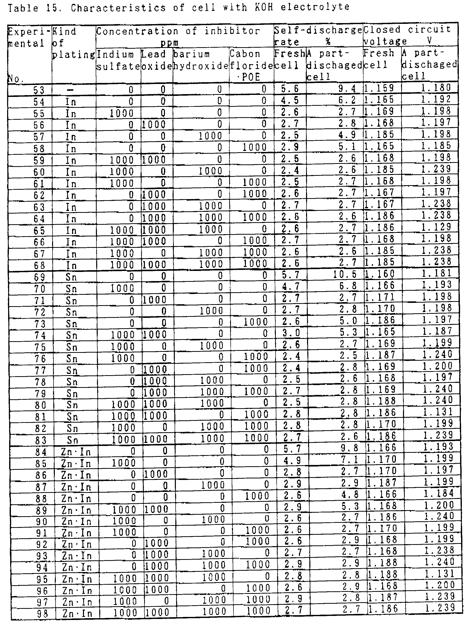

- The inhibitor concentration in the table indicates a value with respect to the zinc weight. The measurement of the self-discharge rate was performed after maintaining it at 60 °C for 20 days, which is said to correspond to 1 year.
- The self-discharge rate after partial discharge was measured by being left at 60 °C for 20 days after 50 % depth discharge (partial discharge). The closed circuit voltage was measured at -10 °C before discharge and after partial discharge.
- As compared with those of no addition of inhibitors (Embodiments No. 54, 69 and 84 in Table 15 and Embodiments No. 100, 115 and 130 in Table 16), those added with inhibitors have small self-discharge rates. With respect to the partial discharge, in the case of those added with one of the type for coating the negative electrode can which being copper such as indium sulfate and lead monoxide, the self-discharge rate is improved. It is understood that the closed circuit voltage becomes high in those added with barium hydroxide. It is understood from the table that when the inhibitor of the coating type and barium hydroxide are added, the self-discharge rate before discharge, the self-discharge rate after partial discharge, and the closed circuit voltage are improved. In the present experiment, a behavior that the closed circuit voltage after partial discharge becomes higher than that before discharge has been presented which is opposite to a case using mercurated zinc. The cause thereof is now under investigation.
- The plating onto the negative electrode can was performed in the same manner as Embodiment 22, and results for each film thickness of 0.3 µ m have been shown. There was little difference in the result even when those having a film thickness of 0.1-1 µ m were used.
- Further, with a battery manufactured using an electrolyte of the KOH type and a negative electrode can applied with indium plating, the self-discharge rate after lapse of corresponding 1 year and the self-discharge rate after partial discharge with respect to the inhibitor concentration were measured.
- Results are shown in Figs. 13 and 14. Provided that the practical range is not more than about 3 % of the self-discharge rate, it has been found that the effect is provided for indium sulfate of 50-5000 ppm, for lead monoxide of 20-5000 ppm, for barium hydroxide of not less than 50 ppm, and for the fluorocarbon-polyoxyethylene type surfactant of not less than 100 ppm as the concentration with respect to zinc. With respect to the self-discharge rate after 50 % depth discharge, the effect was provided for indium sulfate of 50-5000 ppm, and for lead monoxide of 20-5000 ppm. The effect is not provided so much after partial discharge for barium hydroxide, and the fluorocarbon-polyoxyethylene series surfactant. The result has been shown in the case of indium sulfate for indium compounds, however, the effect was also provided for other compounds in substantially the same concentration range. In addition, even when an electrolyte solution of the NaOH series and other negative electrode can plating were used, the concentration range of the inhibitor exhibiting the effect was substantially the same.
- In accordance with Embodiments 25-29, the effect of the case combined each techniques will be explained. In Embodiments 22-24, the evaluation was made using combinations in which the surfactants were changed. In the trial production of batteries, the evaluation was made also by changing the type of zinc.
- Before actually investigating characteristics using batteries, a specially prepared test tube was used to investigate how much amount of hydrogen gas was generated from each of inhibitors and plated copper plates. The method therefor will be described hereinafter.
- Into the specially prepared test tube having a volume of 25 ml and graduated to know the gas generation amount were added beforehand 2 g of zinc powder containing 500 ppm of each of bismuth, indium and lead manufactured by the atomization method, and a copper piece as the same material as a collector having an area of 0.6 cm² and a thickness of 0.1 mm, an electrolyte solution to be tested was added thereto to heat to 60 °C, and the volume of generated hydrogen gas was measured for 7 days. The number of repetition of the test was 10, and an average value thereof was used as a result. The electrolyte solution was prepared such that by making a solution in which potassium hydroxide was 30 % by weight and zinc oxide was added up to approximate saturation in the case of the potassium hydroxide type, or a solution in which sodium hydroxide was 25 % by weight and zinc oxide was added up to approximate saturation in the case of the sodium hydroxide type, as a haze and an inhibitor was optionally added thereto.
- The hydrogen generation from zinc was measured by the combination of a copper plate coated by the electric plating and the substitution plating and the inhibitor. The plating treatment is shown hereinafter.
- method: electric plating
plating bath: indium sulfate 60 g/l, sodium sulfate 10 g/l, 25 °C
plating film thickness: 0.3 µ m - method: electric plating
plating bath: potassium stannate 100 g/l, potassium hydroxide 15 g/l, potassium acetate 5 g/l, 70 °C
planting film thickness: 0.3 µ m - method: contact plating; copper plate and zinc are added into the following plating bath heated to 60°C and left for 1 hour
plating bath: KOH 30 %, ZnO saturation, indium sulfate 0.3 %
plating film thickness: 0.3 µ m
The plating onto the copper plate and the hydrogen gas generation measurement result with respect to the inhibitor are shown as the case using the electrolyte solution of the KOH series in Table 17, while that of the NaOH series in Table 18. The concentration of the inhibitor is shown by a value with respect to the electrolyte solution.Table 17 Hydrogen evolution rate with plated cupper plate Experimental No. Kind of plating Electrolyte Inhibitor (concentration: 100ppm ) Hydrogen evolution rate µ L/g/ day 1 In KOH - 31.43 2 In KOH Indium sulfate 14.28 3 In KOH Indium sulfamate 12.41 4 In KOH Indium hydroxide 16.73 5 In KOH Lead oxide 17.85 6 In KOH Barium hydroxide 8.57 7 In KOH POERA 8.42 8 Sn KOH - 35.78 9 Sn KOH Indium sulfate 16.11 10 Sn KOH Indium sulfamate 17.72 11 Sn KOH Indium hydroxide 16.53 12 Sn KOH Lead oxide 17.91 13 Sn KOH Barium hydroxide 10.89 14 Sn KOH POERA 10.02 15 Zn·In KOH - 32.34 16 Zn·In KOH Indium sulfate 15.27 17 Zn·In KOH Indium sulfamate 13.35 18 Zn·In KOH Indium hydroxide 18.83 19 Zn·In KOH Lead oxide 16.82 20 Zn·In KOH Barium hydroxide 11.30 21 Zn·In KOH POERA 10.98 Table 18 Hydrogen evolution rate with plated cupper plate Experimental No. Kind of plating Electrolyte Inhibitor (concentration: 100ppm ) Hydrogen evolution rate µ L/g/day 22 In NaOH - 29.41 23 In NaOH Indium sulfate 14.75 24 In NaOH Indium sulfamate 10.58 25 In NaOH Indium hydroxide 15.37 26 In NaOH Lead oxide 14.14 27 In NaOH Barium hydroxide 7.82 28 In NaOH POERA 8.13 29 Sn NaOH - 30.10 30 Sn NaOH Indium sulfate 15.03 31 Sn NaOH Indium sulfamate 15.28 32 Sn NaOH Indium hydroxide 15.38 33 Sn NaOH Lead oxide 14.53 34 Sn NaOH Barium hydroxide 8.72 35 Sn NaOH POERA 9.52 36 Zn·In NaOH - 32.83 37 Zn·In NaOH Indium sulfate 14.98 38 Zn·In NaOH Indium sulfamate 13.19 39 Zn·In NaOH Indium hydroxide 14.13 40 Zn·In NaOH Lead oxide 14.27 41 Zn·In NaOH Barium hydroxide 9.98 42 Zn·In NaOH POERA 8.95 - Polyoxyethylene alkylamide is the one (represented by POERA in the table and the figure), in which two polyoxyethylenes (POE) are bonded to the alkyl group at nitrogen through amide bond. In this case, the one having a carbon number of the alkyl group of 11 and a polymerization degree of POE of 15 was used. Usually, when the one having a carbon number of the alkyl group of 3-30 and a polymerization degree of POE of 2-50 is used, the same effect is obtained.
- As compared with the one in which no inhibitor is added, in the case of the one in which the inhibitor of the present invention is added, the hydrogen gas generation amount decreases to about 1/3 to 1/2, and it is understood that there is an effect in relation to suppression of the hydrogen gas generation. The difference due to the plating or the inhibitor is not presented so much. In addition, the hydrogen gas generation amount with respect to the number of test days is shown in Fig. 15 as the measurement result of the case using indium plated copper plates. As for the indium compound, only indium sulfate is shown in the figure.
- In the present Embodiment, the result of the case using the one having a plating film thickness of 0.3 µ m has been shown, however, in practice, also when the one having a film thickness of 0.1-1 µ m was used, there was little difference in the result.
- For comparison, an experiment was performed using non-plated copper plates in the same procedure as Embodiment 25. Experiment results are shown in Table 19 and Fig. 16.
Table 19 Hydrogen evolution rate with not plated cupper plate Example No. Electrolyte Inhibitor (concentration: 100ppm ) Hydrogen evolution rate µ L/g/ day 1 KOH - 516.00 2 KOH Indium sulfate 30.56 3 KOH Indium sulfamate 28.73 4 KOH Indium hydroxide 29.07 5 KOH Lead oxide 24.15 6 KOH Barium hydroxide 480.32 7 KOH Carbon fluoride·POE 432.19 - It is understood that in the case of no addition of the inhibitor and addition of barium hydroxide or the surfactant of the fluorocarbon-polyoxyethylene series, the hydrogen gas generation amount increases with respect to the number of test days exponential functionally. On the other hand, it is understood that in the case of addition of indium sulfate and lead oxide, the generation of hydrogen gas is suppressed. This is due to the fact that the compound of indium or lead has the function to coat the copper plate, but barium hydroxide and the surfactant have such a function a little.
- Using a copper plate plated in the Same manner as Example 25, the hydrogen gas generation in the case of the use of combination of inhibitors was measured using an electrolyte solution of the KOH type. Results are shown in Table 20.
Table 20 Hydrogen evolution rate with indium plated cupper plate and inhibitor Experimental No. Concentration of inhibitor ppm Hydrogen evolution rate µ L/g/day Indium sulfate Lead oxide Indium hydroxide POERA 43 100 100 0 0 15.82 44 100 0 100 0 10.10 45 100 0 0 100 12.28 46 0 100 100 0 14.64 47 0 100 0 100 15.40 48 0 0 100 100 9.28 49 100 100 100 0 14.87 50 100 100 0 100 12.12 51 100 0 100 100 8.88 52 100 100 100 100 8.54 - In the column for the inhibitor in the table, the concentration of each inhibitor added to the electrolyte solution with respect to the electrolyte solution is shown.
- It is understood that the hydrogen gas generation is at a low level in the same manner as Example, and there is not too much bad effect even when a plurality of inhibitors are used. Especially, the hydrogen gas generation is less in the one in which barium hydroxide and polyoxyethylene alkylamide are simultaneously added.
- Next, a battery was actually manufactured, and the effects of the plating on the collector or the inhibitor were investigated.
- Into a positive electrode can were added a part of an electrolyte solution and 116 mg of a pellet (silver oxide content of 98 %) in which silver oxide was added and molded with a combined agent, and a separator of polyethylene and a separator of cellophane were placed. Next, a gasket of nylon was pushed and fitted into the positive electrode can. and filling with an impregnating agent, a gelling agent, and 30 mg of zinc powder, the remainder of the electrolyte solution optionally added with an inhibitor was added dropwise, and then a negative electrode can was placed to perform sealing to manufacture 100 pieces for each kind of button type silver oxide batteries.
- As the zinc powder was used one containing 130 ppm of bismuth, 500 ppm of indium and 30 ppm of aluminum manufactured by atomization.
- The type and the film thickness of plating onto the negative electrode can, the type and the concentration of the added inhibitor, the closed circuit voltage and the self-discharge rate are shown in Tables 21 and 22.


- The inhibitor concentration in the table indicates a value with respect to the zinc weight. The measurement of the self-discharge rate was performed after maintaining at 60 °C for 20 days said to be equivalent to 1 year. The self-discharge rate after partial discharge was measured by being left at 60 °C for 20 days after 50 % depth discharge (partial discharge). The closed circuit voltage was measured at -10 °C before discharge and after partial discharge.
- As compared with those of no addition (Example No. 54, 69 and 84 in Table 21 and Example No. 100, 115 and 130 in Table 22), those added with the inhibitor have small self-discharge rates. With respect to the partial discharge, in the case of those added with one of the type for coating the collector and the zinc surface such as indium sulfate and lead monoxide, the self-discharge rate is improved. It is apparent that the closed circuit voltage is high in those added with barium hydroxide. It is understood from the table that when the inhibitor of the coating type and barium hydroxide are added, the self-discharge rate before discharge, the self-discharge rate after partial discharge, and the closed circuit voltage are improved. In the present experiment, a behavior that the closed circuit voltage after partial discharge becomes higher than that before discharge has been presented which is opposite to a case using mercurated zinc. The cause thereof is now under investigation.
- The plating onto the negative electrode can was performed in the same manner as Example 25, and results for each film thickness of 0.3 µ m have been shown. There was little difference in the result even when those having a film thickness of 0.1-1 µ m were used.
- Further, with a battery manufactured using an electrolyte of the KOH type and a negative electrode can applied with indium plating, the self-discharge rate corresponding to the one after 1 year and the self-discharge rate after partial discharge with respect to the inhibitor concentration were measured.
- Results are shown in Figs. 17 and 18. Provided that the practical range is not more than about 3 % of the self-discharge rate, according to Fig. 17, it has been found to be effective for indium sulfate of 50-5000 ppm, for lead monoxide of 20-5000 ppm, for barium hydroxide of not less than 50 ppm, and for polyoxyethylene alkylamide of not less than 5 ppm as the concentration with respect to zinc.
- With respect to the self-discharge rate after 50 % depth discharge, according to Fig. 18, it was effective for indium sulfate of 50-5000 ppm, and for lead monoxide of 20-5000 ppm. After partial discharge, the effect is not so much for barium hydroxide and polyoxyethylene alkylamide. In order to lower the self-discharge rate after partial discharge, it has been found to be effective to combine and use indium sulfate or lead monoxide and barium hydroxide-polyoxyethylene alkylamide. However, it is desirable that, in the combined use polyoxyethylene alkylamide is not more than 1000 ppm. The result has been shown in the case of indium sulfate for indium compounds, however, other compounds were also effective was in substantially the same concentration range. In addition, even when an electrolyte solution of the NaOH type or other negative electrode can plating were used, the concentration range of the inhibitor exhibiting the effect was substantially the same.
- Trial production of batteries was performed in the same manner as Example 27 by changing the zinc composition. Using an electrolyte solution of the KOH type and plating of indium onto a negative electrode can, and as the inhibitor, each 1000 ppm of indium sulfate, lead monoxide, barium hydroxide and polyoxyethylene alkylamide with respect to zinc was added. Results are shown in Table 23.

- It is apparent that the self-discharge rate is included in a practical range of not more than 3 % in the compositions of additives defined in claims. In order to lower the self-discharge rate, it is desirable to form an alloy of several species.
- In Examples 30-31, results of evaluation mainly for combinations with gelling agents are shown.
- Before practically manufacturing batteries, the effect of the present invention was confirmed in a form of a hydrogen gas generation test. The test was performed using a combination of zinc powder, a gelling agent of the present invention, barium hydroxide and a copper plate of the same material as that of the collector. Into a specially prepared test tube having a volume of 25 ml graduated to know the gas generation amount was added 2 g of zinc powder containing 500 ppm of each of bismuth, indium and lead manufactured by the atomization method, and an electrolyte solution to be tested was added thereto and heated to 60 °C , and the volume of generated hydrogen gas was measured for 7 days. The gelling agent was added by 1.5 % with respect to zinc. Using 2 g of zinc powder and 5 copper pieces as the same material as the collector having a surface area of 0.6 cm² and a thickness of 0.1 mm together so as to provide the same ratio of the negative electrode zinc weight to the negative electrode collector surface area of the battery, the gas generation was measured in the same manner. The number of repetition in the test was 6, and an average value thereof was used as a result.
- The electrolyte solution was prepared by providing a base solution in which potassium hydroxide was 30 % by weight and zinc oxide was added up to approximate saturation in the case of the potassium hydroxide type, or a base solution in which sodium hydroxide was 25 % by weight and zinc oxide was added up to approximate saturation in the case of the sodium hydroxide type, and barium hydroxide was added thereto. Barium hydroxide was made by Wako Pure Chemical Industries., Ltd., CMC was No. 1260 and No. 1380 made by Daicel Chemical Industries, Ltd., and PAS was a reagent made by Wako Pure Chemical Industries., Ltd. and Rheogic 250H made by Nihon Pure Chemicals Co., Ltd. The added amount of barium hydroxide was 0-50000 ppm with respect to the electrolyte solution. Results are shown in the hydrogen generation amount in Table 24.
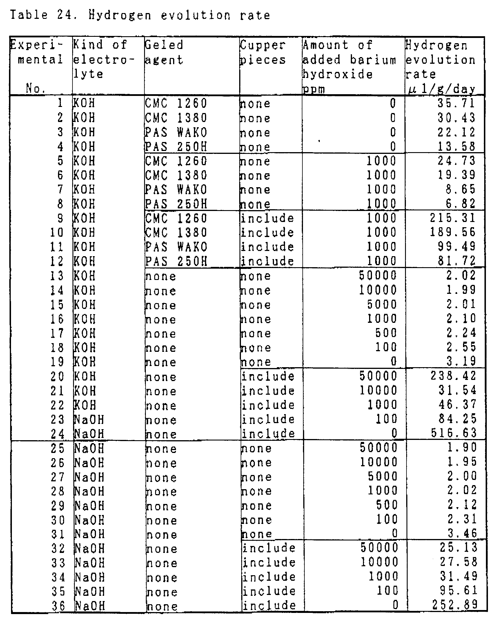
- The unit is µ l/g/day. According to the result in Table 24, it is understood that one added with barium hydroxide has a small hydrogen generation amount irrespective to comparison in the gelling agent type, the zinc powder simple substance and the zinc powder + copper piece, and the electrolyte solution type, and the gas generation is small in PAS being a cross-linked type acrylic water-soluble resin with respect to the gelling agent type.
- It is apparent that the combination of PAS as a cross-linked type acrylic water-soluble resin and barium hydroxide is especially good. When the adding amount of barium hydroxide was not less than 500 ppm, there was supersaturation, so that the electrolyte solution in a turbid state was used. In addition, barium hydroxide was added to the electrolyte solution in Example 30, however, the same effect was obtained even when the whole amount was added to powdery zinc.
- A button type silver oxide battery of the SR621 size was prepared. As a negative electrode can the one in which a collector was applied with tin plating of 0.1 µ m was used. The zinc was the one used in Example 30, Rheogic 250H as a cross-linked type acrylic water-soluble resin for a gelling agent, and a potassium hydroxide 30 % by weight solution or a sodium hydroxide 25 % by weight solution added with zinc oxide up to approximate saturation respectively for an electrolyte solution. The adding amount of the gelling agent was 1.5 % with respect to zinc, and the adding amount of barium hydroxide was 0-50000 ppm with respect to zinc. As Conventional example, a battery was manufactured in which CMC 1260# was used for the gelling agent with no barium hydroxide added. Evaluation results of electric characteristics are shown in the discharge index in Table 25.
Table 25 Chacteristics of cell Experimental No. Kind of electrolyte Amount of added barium hydroxide ppm Comparison of discharge capacity Hydrogen evolution rate µ l/g/ day 1 KOH 50000 97 0.208 2 KOH 10000 100 0.205 3 KOH 1000 103 0.227 4 KOH 100 1023 0.708 5 KOH 10 102 1.693 6 KOH 0 101 1.812 Conventional KOH 0 100 2.513 7 NaOH 50000 98 0.192 8 NaOH 10000 101 0.185 9 NaOH 1000 102 0.183 10 NaOH 100 102 0.228 11 NaOH 10 101 0.342 12 NaOH 0 101 0.549 Conventional NaOH 0 100 0.712 - The electric characteristics were measured by the direct current method with a load resistance of 200 Ω when the electrolyte solution was the potassium hydroxide type or the pulse method with a load resistance of 2 k Ω when it was the sodium hydroxide type. In either case, Conventional example was supposed to have a discharge index of 100. As being apparent also from the result, one in which the gelling agent of the present invention and the cross-linked type acrylic water-soluble resin were used and barium hydroxide was added had a good discharge performance as compared with Conventional example.
- Using a gasket of polypropylene specially prepared for allowing hydrogen to penetrate, a button type silver oxide battery was manufactured in the same manner. As a gelling agent, 1.5 % of Rheogic 250H being a cross-linked type acrylic water-soluble resin was used with respect to zinc. Barium hydroxide had been tested with a concentration of 10 ppm to 5 % with respect to a weight of zinc. Ten pieced of the manufactured silver oxide batteries were placed in a vessel made of glass filled with liquid paraffin in a high temperature tank, a collecting tube having graduations at an upper portion was attached, and the amount of generated hydrogen was measured. This state was maintained at 60 °C for 20 days, and the hydrogen gas generation amount after 20 days was investigated. Evaluation results are shown in the hydrogen gas generation amount in Table 25, and a result of a case using a potassium hydroxide 30 % by weight solution as the electrolyte solution is shown in Fig. 19. According to the figure, it is apparent that barium hydroxide works effectively at 100 ppm to 1 %.
- The gasket made of polypropylene was returned to one made of nylon, and a button type silver oxide battery was manufactured in a range of barium hydroxide concentration of 100 ppm to 1 % which had less gas generation. Ten pieces of the manufactured batteries were placed in a vessel made of glass filled with liquid paraffin in a high temperature tank in the same manner, and a collecting tube for generating hydrogen gas was attached to an upper portion. Hydrogen gas generation, expansion of the battery can and liquid leakage were not observed after 20 days at 60 °C.
- The hydrogen gas generation amount in the actual battery has a value smaller than that of the hydrogen gas generation amount in the experiment in Example 30. For this fact, it is considered that the copper piece used in Example 30 is different from a structure of an actual collector, a part of generated hydrogen gas has been consumed by the reduction of silver oxide and the like. The method in Example 30 is different in the amount order of hydrogen gas generation, but it is sufficient as a method for observing substituted characteristics for predicting hydrogen generation in an actual battery.
- In accordance with Examples 32-35, the effect of a case in which the collector is provided with a zinc alloy layer and evaluation results of a case in which the alkaline battery of the present invention is used for a clock or watch are shown.
- Before actually investigating characteristics using batteries, a specially prepared test tube was used to investigate what amount of hydrogen gas was generated from a plated copper plate (the same material as a collector). The method therefor will be described hereinafter.
- Into a specially prepared test tube having a volume of 25 ml graduated to know the gas generation amount were placed beforehand 2 g of zinc powder containing 500 ppm of each of bismuth, indium and lead manufactured by the atomization method, and a copper piece being the same material as the collector and having art area of 0.6 cm² and a thickness of 0.1 mm being applied with plating of the present invention, an electrolyte solution was added thereto and heated to 60 °C, and the volume of generated hydrogen gas was measured for 7 days. The number of repetition of the test was 10, and an average value thereof was used as a result. As the electrolyte solution was used a solution in which potassium hydroxide was 30 % by weight and zinc oxide was added up to approximate saturation in the case of the potassium hydroxide type, and a solution in which sodium hydroxide was 25 % by weight and zinc oxide was added up to approximate saturation in the case of the sodium hydroxide type.
- The hydrogen generation from zinc and a copper piece coated with the electric plating and the substitution plating was measured. Four kinds of plating treatments onto the copper piece were performed. Conditions are shown hereinafter.
- method: contact plating: A copper piece and zinc were placed into the following plating bath heated to 60 °C and left for 1 hour.
plating bath: KOH 30 %, ZnO saturation, indium sulfate 0-3000 ppm
temperature: 60 °C
plating film thickness: Adjustment was made depending on time. The thickness was determined from weights before and after the plating. - method; contact plating: A copper piece and zinc were placed into the following plating bath heated to 60 °C and left for 1 hour.
plating bath: KOH 30 %, ZnO saturation, lead oxide 0-3000 ppm
temperature: 60 °C
plating film thickness: Adjustment was made depending on time. The thickness was determined from weights before and after the plating. - method: A copper piece was clamped in a net made of copper to allow a current to flow, and plating was performed. The copper piece was suitably moved so as not to make a portion not subjected to plating.
plating bath: zinc cyanide 70 g/l, sodium cyanide 50 g/l, sodium hydroxide 100 g/l, indium cyanide 0-3000 ppm
temperature: 25 °C
current density: 5 A/dm²
plating film thickness: Adjustment was made depending on time. The thickness was determined from weights before and after the plating. - method: A copper piece was clamped in a net made of copper to allow a current to flow, and plating was performed. The copper piece was suitably moved so as not to make a portion not subjected to plating.
plating bath: zinc sulfate 240 g/l, sodium sulfate 30 g/l, sodium acetate 15 g/l, indium sulfate 0-3000 ppm
temperature; 25 °C
current density: 2 A/dm²
plating film thickness: Adjustment was made depending on time. The thickness was determined from weights before and after the plating. - A copper piece subjected to each treatment, zinc powder and an electrolyte solution were added in a specially prepared test tube, and the amount of hydrogen gas generated therefrom was investigated. It is supposed that the larger the hydrogen gas generation, the larger is the self-discharge in an actual battery.
Table 26 Hydrogen evolution rate in KOH electrolyte Experimental No. Condition of plating Hydrogen evolution rate (µ l/g/day) vs concentration of additive in plating solution (ppm) Kind of plating Additive 0 10 100 1000 3000 1 Contact plating Indium sulfate 516.92 14.29 10.71 12.14 8.57 2 Contact plating PbO ↑ 13.28 12.96 96.34 120.36 3 Electroplating Indium cyanide ↑ 15.47 13.22 10.25 10.81 4 Electroplating Indium sulfate ↑ 18.24 15.26 15.13 7.41 Table 27 Hydrogen evolution rate in NaOH electrolyte Experimental No. Condition of plating Hydrogen evolution rate (µ l/g/day) vs concentration of additive in plating solution (ppm) Kind of plating Additive 0 10 100 1000 3000 5 Contact plating Indium sulfate 480.23 13.00 10.17 11.53 7.11 6 Contact plating PbO ↑ 12.75 11.28 90.56 102.31 7 Electroplating Indium cyanide ↑ 14.54 12.82 9.43 9.84 8 Electroplating Indium sulfate ↑ 18.06 14.19 14.98 6.45 - In Table 26, the hydrogen generation amount in the KOH type electrolyte solution with respect to the copper piece plated with each concentration of lead oxide is shown. In Table 27, the result in the NaOH type electrolyte solution is shown.
- According to Tables 26 and 27, it is understood that the hydrogen gas generation can be greatly suppressed as by adding a little amount of indium compound and lead oxide of about 10 ppm into the plating solution, and forming an alloy of the plating film as compared with no addition. However, in the case of addition of lead oxide in a high concentration, needle-like lead becomes deposited on the plating film, and the hydrogen gas generation is deteriorated.
- When the copper piece subjected to the substitution plating was quantitatively measured by the Auger spectroscopic analysis, it was found that about 0.3 % of indium existed in the plating film in the case of adding indium sulfate in an amount of 1000 ppm, and about 0.1 % of indium existed in the case of adding an amount of 100 ppm. In the case of the plating film manufactured by adding indium sulfate to the plating solution by not more than 100 ppm, it was impossible to measure indium as being not more than the detection limit. However, it is considered that the hydrogen gas generation suppressing effect is obtained by the inclusion of an extremely minute amount of indium into the plating film. For other kinds of plating, it is considered that, in the same manner the hydrogen gas generation suppressing effect is obtained because indium and lead are deposited in zinc, to lower the hydrogen overvoltage of zinc.

- In Tables 28 and 29, the hydrogen gas generation amount with respect to the film thickness is shown in the substitution plating added with 1000 ppm of indium sulfate. According to Tables 28 and 29, it is apparent that the effect is provided from 0.015 µ m as being fairly thin.
- Next, trial production of a battery was actually performed to confirm the effect on the negative electrode can.
- Into a positive electrode can were added a part of an electrolyte solution and placing thereinto 116 mg of a pellet (silver oxide content of 98 %) made by adding silver oxide being and molded with a combined agent, a separator of polyethylene and a separator of cellophane. Next, a gasket of nylon was pushed and fitted into the positive electrode can, an impregnating agent, a gelling agent, and 30 mg of zinc powder were added, the remainder of the electrolyte solution optionally added with an inhibitor was added dropwise, then a negative electrode can was placed and sealed to manufacture 100 pieces for each kind of button type silver oxide batteries.
- As the zinc powder was used one containing 500 ppm of bismuth, 500 ppm of indium and 500 ppm of lead manufactured by atomization. The plating onto the negative electrode can was performed in the same manner as Example 32.
- The self-discharge rate with respect to the type of the plating onto the negative electrode can is shown in Tables 30 and 31. The measurement of the self-discharge rate was performed after maintaining 60 °C for 20 days as said to be equivalent to 1 year.
Table 30 Self-discharge rate of cell with KOH electrolyte Experimental No. Condition of plating Self-discharge rate after 1 year storage % Kind of plating Additive 11 none - 5.8 12 Contact plating Indium sulfate 2.5 13 Contact plating PbO 2.8 14 Electroplating Indium cyanide 2.4 15 Electroplating Indium sulfate 2.4 Table 31 Self-discharge rate of cell with NaOH electrolyte Experimental No. Condition of plating Self-discharge rate after 1 year storage % Kind of plating Additive 16 none - 5.5 17 Contact plating Indium sulfate 2.2 18 Contact plating PbO 2.5 19 Electroplating Indium cyanide 2.1 20 Electroplating Indium sulfate 2.2 - According to Tables 30 and 31, it is understood that the self-discharge can be suppressed by using the plated negative electrode can of the present invention as compared with the negative electrode can not subjected to plating.
- In this case, results are shown in which the adding amount of the indium Compound into the plating solution was 1000 ppm, the adding amount of lead oxide was 100 ppm, and each film thickness was 0.1 µ m. There was little difference in the result even when those having a film thickness of 0.01-3 µ m were used. In addition, equivalent effects were obtained in ranges in which the amount of the indium compound added into the plating solution was 10-3000 ppm, and the amount of lead oxide added was 10-100 ppm. When the same test was performed for potassium stannate and sodium stannate, equivalent effects were obtained in a range of the adding amount of 10-3000 ppm. In addition, equivalent effects were obtained even when plating solutions mixed and added with indium compounds, lead oxide, potassium stannate and sodium stannate in these concentration ranges have been used.
- A test was performed for the impurity shielding effect of the plating film.
- Plating was performed for a negative electrode can having the SR521 size in which iron type foreign matters had adhered to the collector surface during press processing causing deficiency in gas generation. The deficiency in gas generation may become a cause of expansion and explosion when a battery is made, which can be confirmed by instant gas generation after adding an electrolyte solution and several zinc powder particles of about 100 µ m to a concave surface at the copper side being the collector of the negative electrode can. This is due to the fact that zinc serves as an anode and iron having a lower hydrogen overvoltage serves as a cathode to generate hydrogen. The plating was performed by the substitution plating using a barrel. Conditions are described hereinafter.
- method: contact plating: Using a barrel, a negative electrode can and a zinc piece were added into the following plating solution heated to 60 °C to perform plating.
negative electrode can; SR521 size, about 1000 pieces
zinc piece: 3 x 3 x 0.1, about 1500 sheets
plating solution: KOH 30 %, ZnO saturation, indium sulfate 0-300 ppm
temperature: 60 °C
time: 5, 15 and 30 minutes
plating film thickness; The thickness was measured from weights of a copper plated added as a dummy before and after the plating. - The film thickness against time was 0.041 µ m for 5 minutes, 0.090 µ m for 15 minutes, and 0.148 µ m for 30 minutes. 100 pieces were picked out respectively, and the confirmation of gas generation was performed. As a result, the gas generation was found in 78 pieces out of 100 pieces in the case of those subjected to plating for 5 minutes. No gas generation was found in those subjected to plating for 15 and 30 minutes. According to this fact, it has been found that a plating thickness of about 0.1 µ m has shielding effect for impurities.
- Next, results are shown for a case in which the shaping into a negative electrode can was performed after plating onto a hoop material instead of the direct negative electrode can plating as done in Example 33. In this case, although there is a merit that the plating can be made thick by the electric plating, however, there is a problem that deficiency is apt to be caused in a soft plating film by mechanical processing. Plating conditions are shown hereinafter.
- method: The nickel side of a hoop material clad of three-layers of nickel, stainless and copper was subjected to masking, and plating was performed onto the copper side.
plating bath: zinc cyanide 70 g/l, sodium cyanide 50 g/l, sodium hydroxide 100 g/l,indium cyanide 1000 ppm
bath temperature; 25 °C
Current density: 5 A/dm²
plating film thickness: Adjustment was made depending on time. The thickness (adjustment of the feed speed of the hoop material) was determined by embedding in a resin and taking a picture using an optical microscope. - Those having a film thickness of 1, 2, 3, 4, 7 or 10 µ m were manufactured. Negative electrode cans of 100 pieces were manufactured using each hoop material plated with a zinc alloy of each film thickness. The number of negative electrode cans in which the copper surface became exposed by processing was investigated. Results are shown in Table 7.
- According to the result, it is apparent that the copper surface ceases to be exposed in the case of not less than 3 µ m.
- The negative electrode cans of each film thickness were used to perform trial production of 100 pieces of batteries respectively with an NaOH type electrolyte solution in the same manner as Example 33.
Table 32 Number of anode cap with generated pinhole and self-discharge rate Plating thickness ( µ m) 1 2 3 4 7 10 Cell using analgamated zinc Number of anode cap with generated pinhole 8 3 0 0 0 0 Initial capacity (mAh) 23.2 23.3 23.4 23.6 24.1 24.8 23.1 Capacity after 2 years storage (mAh) 21.2 21.7 22.0 22.7 23.0 23.8 22.6 Self-discharge rate (%/year) 4.4 3.5 2.9 1.9 2.1 2.0 1.1 - The initial capacity and the capacity corresponding to the one after 2 years (after storage at 60 °C for 40 days) are shown in Table 32. A result of a case where mercurated zinc was used, is also described at the right end in the table for the purpose of comparison. According to Table 32, the plating of not more than 2 µ m has a capacity smaller than that of the case in which direct plating was performed to the negative electrode can in Example 33, due to deficiency in the plating film by processing. When the film thickness if 4 µ m, the capacity after 2 years becomes approximately the same as the one in which mercurated zinc is used. For example, when the battery is incorporated into a clock or watch, the battery service life is about 2 years. In order to expect a capacity equivalent to or not less than that of a battery using mercurated zinc after 2 years, it is necessary to plate the zinc alloy by not less than 4 µ m according to Table 32. In the design of a battery, it is available that the zinc alloy plating thickness may be not less than 3 µ m so as to have a thickness with which an aimed capacity is obtained in 2 years.
- A conventional battery in which zinc having a mercuration ratio of 10 % was used and a battery in which a 4 µ m zinc-indium alloy was applied to a negative electrode can of the present invention by the same method as Example 35 using mercuryless zinc were actually installed in wristwatches, and a carrying test was performed to measure the number of days until the watch stopped. The test was done for each 10 pieces.
Table 33 Cell life by watch Cell using amalgamated zinc Cell using zinc without mercury and plated anode cap (plating thickness:4 µ m) Cell life(days) 751.1 758.3 σ 14.8 23.6 - Results are shown in Table 33. The number of days until the watch stopped was substantially the same, and coming off with the capacity not being lowered even in the case of no mercury.
- As shown in Example 35, it is apparent that when using as a standard a film thickness, in which the capacity after 2 years in the acceleration test becomes the same as that of the battery using mercurated zinc, it is possible to obtain a capacity equivalent to the one in which mercurated zinc is used also when used in an actual clock or watch.
- Namely, in the design of a battery, the zinc alloy plating thickness may be made to be not less than 3 µ m so as to provide a thickness with which an aimed capacity is obtained in 2 years. For example, provided that the weight of zinc in the battery using mercurated zinc of an aimed capacity (excluding an amount of mercury) is W0, the self-discharge rate / year is SD0, the weight of zinc in the battery using mercuryless zinc to be designed is W0 (the same as mercurated zinc), the self-discharge rate is SD1, the area of the collector is S, and the specific gravity of zinc is 7.13, the film thickness D1 of the zinc alloy may be as follows:

In the present Examples 35 and 36, it has been described that the clad material is plated with the zinc-indium alloy of not less than 3 µ m, however, as shown in Examples 32 and 33, approximately the same effect is obtained provided that the zinc alloy is an alloy containing zinc as an essential element and containing one or more species selected from indium, lead and tin as a selective element. In addition, it is needless to say that the same effect is obtained even when the formation method of the zinc alloy layer is another method, For example, methods cladding a zinc alloy with one more layer, or using dry plating or flame coating and the like are applicable. - In addition, the effect of the invention is not deteriorated even when elements which raise the hydrogen overvoltage of the zinc alloy such as bismuth, gallium, aluminum, calcium and the like exist in the zinc alloy layer containing indium or lead. Depending on the way of addition, further self-discharge suppressing effects can be expected.
- As also described in Examples hereinbefore, according to the present invention, it is possible to manufacture the alkaline battery in which the generation of hydrogen is suppressed without deteriorating battery characteristics. This is especially effective for coin type or button type alkaline batteries which require high performance but are sensitive to gas generation.
- In addition, with respect to the zinc alloy plating onto the collector of the present invention, when it is used for minute discharge for clocks or watches or the like, it is possible to achieve a capacity which is equivalent to or not less than those of batteries in which mercurated zinc is used. Further, when clocks or watches carrying the alkaline batteries of the present invention are discarded, the environment is never polluted because mercury as an environmental pollution substance is not contained. When a applied product carrying the alkaline batteries are discarded, the environment is never polluted because mercury as an environmental pollution substance is not contained.
The plating onto the copper plate and the hydrogen gas generation measurement result with respect to the inhibitor are shown as the case using the electrolyte solution of the KOH series in Table 11 and that of the NaOH type in Table 12.
| Hydrogen evolution rate with plated cupper plate | ||||
| Experimental No. | Kind of plating | Electrolyte | Inhibitor (concentration: 100ppm ) | Hydrogen evolution rate µ L/g/ |
| 1 | In | KOH | - | 31.43 |
| 2 | In | KOH | Indium sulfate | 14.28 |
| 3 | In | KOH | Indium sulfamate | 12.41 |
| 4 | In | KOH | Indium hydroxide | 16.73 |
| 5 | In | KOH | Lead oxide | 17.85 |
| 6 | In | KOH | Barium hydroxide | 8.57 |
| 7 | In | KOH | Carbon fluoride·POE | 12.14 |
| 8 | Sn | KOH | - | 35.78 |
| 9 | Sn | KOH | Indium sulfate | 16.11 |
| 10 | Sn | KOH | Indium sulfamate | 17.72 |
| 11 | Sn | KOH | Indium hydroxide | 16.53 |
| 12 | Sn | KOH | Lead oxide | 17.91 |
| 13 | Sn | KOH | Barium hydroxide | 10.89 |
| 14 | Sn | KOH | Carbon fluoride·POE | 14.38 |
| 15 | Zn·In | KOH | - | 32.34 |
| 16 | Zn·In | KOH | Indium sulfate | 15.27 |
| 17 | Zn·In | KOH | Indium sulfamate | 13.35 |
| 18 | Zn·In | KOH | Indium hydroxide | 18.83 |
| 19 | Zn·In | KOH | Lead oxide | 16.82 |
| 20 | Zn·In | KOH | Barium hydroxide | 11.30 |
| 21 | Zn·In | KOH | Carbon fluoride·POE | 13.01 |
| Hydrogen evolution rate with plated cupper plate | ||||
| Experimental No. | Kind of plating | Electrolyte | Inhibitor (concentration: 100ppm ) | Hydrogen evolution rate µ L/g/day |
| 22 | In | NaOH | - | 29.41 |
| 23 | In | NaOH | Indium sulfate | 14.75 |
| 24 | In | NaOH | Indium sulfamate | 10.58 |
| 25 | In | NaOH | Indium hydroxide | 15.37 |
| 26 | In | NaOH | Lead oxide | 14.14 |
| 27 | In | NaOH | Barium hydroxide | 7.82 |
| 28 | In | NaOH | Carbon fluoride·POE | 9.34 |
| 29 | Sn | NaOH | - | 30.10 |
| 30 | Sn | NaOH | Indium sulfate | 15.03 |
| 31 | Sn | NaOH | Indium sulfamate | 15.28 |
| 32 | Sn | NaOH | Indium hydroxide | 15.38 |
| 33 | Sn | NaOH | Lead oxide | 14.53 |
| 34 | Sn | NaOH | Barium hydroxide | 8.72 |
| 35 | Sn | NaOH | Carbon fluoride·POE | 12.43 |
| 36 | Zn·In | NaOH | - | 32.83 |
| 37 | Zn·In | NaOH | Indium sulfate | 14.98 |
| 38 | Zn·In | NaOH | Indium sulfamate | 13.19 |
| 39 | Zn·In | NaOH | Indium hydroxide | 14.13 |
| 40 | Zn·In | NaOH | Lead oxide | 14.27 |
| 41 | Zn·In | NaOH | Barium hydroxide | 9.98 |
| 42 | Zn·In | NaOH | Carbon fluoride·POE | 9.84 |
Claims (52)
- An alkaline battery comprising:
mercuryless zinc powder as a negative electrode active material; and
an electrolyte solution, the electrolyte Solution being added with any one species selected from indium sulfate, indium sulfamate and indium chloride. - An alkaline battery comprising:
mercuryless zinc powder as a negative electrode active material, the negative electrode active material being added with any one species selected from indium sulfate, indium sulfamate and indium chloride. - An alkaline battery comprising:
mercuryless zinc powder as a negative electrode active material; and
an electrolyte solution, the electrolyte solution being added with an indium compound and a complexing agent. - An alkaline battery according to claim 3 wherein said complexing agent is any one species selected from tartarate, EDTA and cyanate.
- A method for producing alkaline batteries according to claim 3 comprising:
a step for dissolving a complexing agent in the electrolyte solution prior to the indium compound. - An alkaline battery comprising:
mercuryless zinc powder as a negative electrode active material, the negative electrode active material being added with an indium compound and a complexing agent. - An alkaline battery according to claim 6 wherein said complexing agent is any one species selected from tartarate, EDTA and cyanate.
- An alkaline battery comprising;
mercuryless zinc powder as a negative electrode active material; and
an electrolyte solution, the electrolyte solution being added with two or more speices of compounds selected from an indium compound, a tin compound containing tetravalent tin, and lead oxide. - An alkaline battery according to claim 8 wherein said indium compound is indium sulfate, indium sulfamate, indium chloride and indium hydroxide.
- An alkaline battery according to claim 8 wherein said tetravalent tin compound is a stannate such as potassium stannate, sodium stannate or the like and stannic oxide.
- An alkaline battery comprising:
mercuryless zinc powder as a negative electrode active material, the negative electrode active material being added with two or more species of compounds selected from an indium compound, a tin compound containing tetravalent tin, and lead oxide. - An alkaline battery according to claim 11 wherein said indium compound is indium sulfate, indium sulfamate, indium chloride and indium hydroxide.
- An alkaline battery according to claim 11 wherein said tetravalent tin compound is a stannate such as potassium stannate, sodium stannate or the like and stannic oxide.
- An alkaline battery comprising:
mercuryless zinc powder containing indium as a negative electrode active material; and
an electrolyte solution, the electrolyte solution being added with one or more species of compounds selected from an indium compound, a tin compound containing tetravalent tin, and lead oxide. - An alkaline battery comprising:
mercuryless zinc powder containing indium as a negative electrode active material, the negative electrode active material being added with one or more species of compounds selected from an indium compound, a tin compound containing tetravalent tin, and lead oxide. - An alkaline battery comprising:
mercuryless zinc powder as a negative electrode active material, a concentration of iron included in the mercuryless zinc powder being not more than 4 ppm with respect to zinc; and
an electrolyte solution, the electrolyte solution being added with one or more species of compounds selected from an indium compound, a thin compound containing tetravalent tin, and lead oxide. - An alkaline battery comprising:
mercuryless zinc powder as a negative electrode active material, a concentration of iron included in the mercuryless zinc powder being not more than 4 ppm with respect to zinc, the negative electrode active material being added with one or more species of compounds selected from an indium compound, a tin compound containing tetravalent tin, and lead oxide. - A silver oxide battery comprising:
mercuryless zinc as a negative electrode active material, the mercuryless zinc containing at least one species of metal selected from the group consisting of 0.001-0.5 % by weight of gallium, 0.005-0.5 % by weight of indium, 0.0001-0.5 % by weight of lead, 0.005-0.5 % by weight of bismuth, 0.001-0.5 % by weight of aluminum, and 0.001-0.5 % by weight of calcium, and the balance comprising zinc and inevitable impurities;
an amount of water in the battery being 0.31-0.57 mg per a weight of 1 mg of the mercuryless zinc; and
an electrolyte being potassium hydroxide. - A silver oxide battery comprising:
mercuryless zinc as a negative electrode active material, the mercuryless zinc containing at least one species of metal selected from the group consisting of 0.001-0.5 % by weight of gallium, 0.005-0.5 % by weight of indium, 0.0001-0.5 % by weight of lead, 0.005-0.5 % by weight of bismuth, 0.001-0.5 % by weight of aluminum, and 0.001-0.5 % by weight of calcium, and the balance comprising zinc and inevitable impurities;
an amount of water in the battery being 0.32-0.59 mg per a weight of 1 mg of the mercuryless zinc; and
an electrolyte being sodium hydroxide. - An alkaline battery comprising:
mercuryless zinc powder containing a gelling agent as a negative electrode active material;
an outermost layer of a collector comprising a layer of zinc or metal having a hydrogen overvoltage higher than that of zinc; and
an electrolyte solution, the electrolyte solution being added with one or more species of materials selected from an indium compound, lead oxide, hydroxide of alkaline earth metal, a surfactant having polyethylene oxide. - The alkaline battery according to claim 20 wherein said zinc gelling agent is a cross-linked type polyacrylic water-absorbing polymer alone or a combination thereof with other gelling agents.
- The alkaline battery according to claim 20 wherein said mercuryless zinc powder is mercuryless zinc powder containing at least one species of the group of 0.001-0.5 % by weight of gallium, 0.005-0.5 % by weight of indium, 0.0001-0.5 % by weight of lead, 0.005-0.5 % by weight of bismuth, 0.001-0.5 % by weight of aluminum, and 0.001-0.5 % by weight of calcium.
- The alkaline battery according to claim 20 wherein said layer of zinc or metal having a hydrogen overvoltage higher than that of zinc is one or more species of metal or alloy selected from zinc, indium, tin and lead.
- The alkaline battery according to claim 20 wherein said indium compound is indium sulfate, indium sulfamate, indium chloride and indium hydroxide.
- The alkaline battery according to claim 20 wherein said hydroxide of alkaline earth metal is barium hydroxide.
- The alkaline battery according to claim 20 wherein said surfactant having polyethylene oxide is added with one or more species of materials selected from a surfactant having fluorocarbon at the hydrophobic portion and polyethylene oxide at the hydrophilic portion, or polyoxyethylene alkylamide.
- An alkaline battery comprising:
mercuryless zinc powder containing a gelling agent as a negative electrode active material, the negative electrode active material being added with one or more species of materials selected from an indium compound, lead oxide, hydroxide of alkaline earth metal, a surfactant having polyethylene oxide; and
an outermost layer of a collector comprising a layer of zinc or metal having a hydrogen overvoltage higher than that of zinc. - The alkaline battery according to claim 27 wherein said zinc gelling agent is a cross-linked type polyacrylic water-absorbing polymer alone or a combination thereof with other gelling agents.
- The alkaline battery according to claim 27 wherein said mercuryless zinc powder is mercuryless zinc powder containing at least one species of the group of 0.001-0.5 % by weight of gallium, 0.005-0.5 % by weight of indium, 0.0001-0.5 % by weight of lead, 0.005-0.5 % by weight of bismuth, 0.001-0.5 % by weight of aluminum, and 0.001-0.5 % by weight of calcium.
- The alkaline battery according to claim 27 wherein said layer of zinc or metal having a hydrogen overvoltage higher than that of zinc is one or more species of metal or alloy selected from zinc, indium, tin and lead.
- The alkaline battery according to claim 27 wherein said indium compound is indium sulfate, indium sulfamate, indium chloride or indium hydroxide.
- The alkaline battery according to claim 27 wherein said hydroxide of alkaline earth metal is barium hydroxide.
- The alkaline battery according to claim 28 characterized in that said surfactant having polyethylene oxide is added with one or more species of materials selected from a surfactant having fluorocarbon at the hydrophobic portion and polyethylene oxide at the hydrophilic portion, or polyoxyethylene alkylamide.
- An alkaline battery comprising:
mercuryless zinc powder as a negative electrode active material; and
an outermost layer of a collector comprising art alloy layer containing zinc as an essential element, and containing one or more species selected from indium, lead and tin as a selective element. - The alkaline battery according to claim 34 wherein said alloy layer is formed by plating said outermost layer of said collector.
- An alkaline battery comprising:
mercuryless zinc powder as a negative electrode active material; and
an outermost layer of a collector comprising an alloy layer containing zinc as an essential element, and containing one or more species selected from indium, lead and tin as a selective element, the alloy layer being not less than 3 µ m. - An applied product using art alkaline battery comprising:
mercuryless zinc powder as a negative electrode active material; and
an outermost layer of a collector comprising an alloy layer containing zinc as an essential element, and containing one or more species selected from indium and lead as a selective element, the alloy layer being not less than 3 µ m. - An applied product using an alkaline battery comprising:
mercuryless zinc powder as a negative electrode active material; and
an electrolyte solution, the electrolyte solution being added with any one species selected from indium sulfate, indium sulfamate and indium chloride. - An applied product using an alkaline battery comprising:
mercuryless zinc powder as a negative electrode active material, the negative electrode active material being added with any one species selected from indium sulfate, indium sulfamate and indium chloride. - An applied product using an alkaline battery comprising:
mercuryless zinc powder as a negative electrode active material; and
an electrolyte solution, the electrolyte solution being added with an indium compound and a complexing agent. - An applied product using an alkaline battery comprising:
mercuryless zinc powder as a negative electrode active material, the negative electrode active material being added with an indium compound and a complexing agent. - An applied product using an alkaline battery comprising:
mercuryless zinc powder as a negative electrode active material; and
an electrolyte solution, the electrolyte solution being added with two or more species of compounds selected from an indium compound, a tin compound containing tetravalent tin, and lead oxide. - An applied product using an alkaline battery comprising:
mercuryless zinc powder as a negative electrode active material, the negative electrode active material being added with two or more species of compounds selected from an indium compound, a tin compound containing tetravalent tin, and lead oxide. - An applied product using an alkaline battery comprising:
mercuryless zinc powder containing indium as a negative electrode active material; and
an electrolyte solution, the electrolyte solution being added with one or more species of compounds selected from an indium compound, a tin compound containing tetravalent tin, and lead oxide. - An applied product using an alkaline battery comprising:
mercuryless zinc powder containing indium as a negative electrode active material, the negative electrode active material being added with one or more species of compounds selected
from an indium compound, a tin compound containing tetravalent tin, and lead oxide. - An applied product using an alkaline battery comprising:
mercuryless zinc powder as a negative electrode active material, a concentration of iron included in the mercuryless zinc powder being not more than 4 ppm with respect to zinc; and
an electrolyte solution, the electrolyte Solution being added with one or more species of compounds selected from an indium compound, a tin compound containing tetravalent tin, and lead oxide. - An applied product using an alkaline battery comprising:
mercuryless zinc powder as a negative electrode active material, a concentration of iron included in the mercuryless zinc powder being not more than 4 ppm with respect to zinc, the negative electrode active material being added with one or more species of compounds selected from an indium compound, a tin compound containing tetravalent tin, and lead oxide. - An applied product using a silver oxide battery comprising:
mercuryless zinc as a negative electrode active material, the mercuryless zinc containing at least one species of metal selected from the group consisting of 0.001-0.5 % by weight of gallium, 0.005-0.5 % by weight of indium, 0.0001-0.5 % by weight of lead, 0.005-0.5 % by weight of bismuth, 0.001-0.5 % by weight of aluminum, and 0.001-0.5 % by weight of calcium, and the balance comprising zinc and inevitable impurities;
an amount of water in the battery being 0.31-0.57 mg per a weight of 1 mg of the mercuryless zinc; and
an electrolyte being potassium hydroxide. - An applied product using a silver oxide battery comprising:
mercuryless zinc as a negative electrode active material, the mercuryless zinc containing at least one species of metal selected from the group consisting of 0.001-0.5 % by weight of gallium, 0.005-0.5 % by weight of indium, 0.0001-0.5 % by weight of lead, 0.005-0.5 % by weight of bismuth, 0,001-0.5 % by weight of aluminum, and 0.001-0.5 % by weight of calcium, and the balance comprising zinc and inevitable impurities;
an amount of water in the battery being 0.32-0.59 mg per a weight of 1 mg of the mercuryless zinc; and
an electrolyte being sodium hydroxide. - An applied product using an alkaline battery comprising:
mercuryless zinc powder containing a gelling agent as a negative electrode active material;
an outermost layer of a collector comprising a layer of zinc or metal having a hydrogen overvoltage higher than that of zinc; and
an electrolyte solution, the electrolyte solution being added with one or more species of materials selected from an indium compound, lead oxide, hydroxide of alkaline earth metal, a surfactant having polyethylene oxide. - An applied product using an alkaline battery comprising:
mercuryless zinc powder containing a gelling agent as a negative electrode active material, the negative electrode active material being added with one or more species of materials selected from an indium compound, lead oxide, hydroxide of alkaline earth metal, a surfactant having polyethylene oxide; and
an outermost layer of a collector comprising a layer of zinc or metal having a hydrogen overvoltage higher than that of zinc. - An applied product using an alkaline battery comprising:
mercuryless zinc powder as a negative electrode active material; and
an outermost layer of a collector comprising an alloy layer containing zinc as an essential element, and containing one or more species selected from indium, lead and tin as a selective element.
Applications Claiming Priority (22)
| Application Number | Priority Date | Filing Date | Title |
|---|---|---|---|
| JP207925/92 | 1992-08-04 | ||
| JP20792792 | 1992-08-04 | ||
| JP207926/92 | 1992-08-04 | ||
| JP20792592 | 1992-08-04 | ||
| JP20792692 | 1992-08-04 | ||
| JP207927/92 | 1992-08-04 | ||
| JP209008/92 | 1992-08-05 | ||
| JP20900892 | 1992-08-05 | ||
| JP238263/92 | 1992-09-07 | ||
| JP238264/92 | 1992-09-07 | ||
| JP23826392 | 1992-09-07 | ||
| JP23826492 | 1992-09-07 | ||
| JP311707/92 | 1992-11-20 | ||
| JP31170792 | 1992-11-20 | ||
| JP11210/93 | 1993-01-26 | ||
| JP1121093 | 1993-01-26 | ||
| JP1295693 | 1993-01-28 | ||
| JP12956/93 | 1993-01-28 | ||
| JP9168493 | 1993-04-19 | ||
| JP91684/93 | 1993-04-19 | ||
| JP16296493A JP3553104B2 (en) | 1992-08-04 | 1993-06-30 | Alkaline battery |
| JP162964/93 | 1993-06-30 |
Publications (2)
| Publication Number | Publication Date |
|---|---|
| EP0582293A2 true EP0582293A2 (en) | 1994-02-09 |
| EP0582293A3 EP0582293A3 (en) | 1996-08-14 |
Family
ID=27581810
Family Applications (1)
| Application Number | Title | Priority Date | Filing Date |
|---|---|---|---|
| EP93112516A Withdrawn EP0582293A3 (en) | 1992-08-04 | 1993-08-04 | Alkaline battery, production method of alkaline battery, and applied product using alkaline battery |
Country Status (4)
| Country | Link |
|---|---|
| US (2) | US6586139B1 (en) |
| EP (1) | EP0582293A3 (en) |
| JP (1) | JP3553104B2 (en) |
| KR (1) | KR940006308A (en) |
Cited By (12)
| Publication number | Priority date | Publication date | Assignee | Title |
|---|---|---|---|---|
| WO1995031011A1 (en) * | 1994-05-06 | 1995-11-16 | Battery Technologies Inc. | Sealed rechargeable cells containing mercury-free zinc anodes, and a method of manufacture |
| EP0768723A1 (en) * | 1995-10-16 | 1997-04-16 | Rayovac Corporation | Low mercury content electrochemical cell |
| FR2742927A1 (en) * | 1995-12-21 | 1997-06-27 | Leclanche Sa | Mercury-free miniature alkaline cell |
| EP0802573A2 (en) | 1996-04-20 | 1997-10-22 | VARTA Batterie Aktiengesellschaft | Galvanic cell |
| EP0686207B1 (en) * | 1993-02-25 | 2000-04-26 | n.v. UNION MINIERE s.a. | Zinc powder for alkaline batteries |
| WO2001033658A3 (en) * | 1999-10-29 | 2001-10-18 | Eontech Group Inc | Metal-air battery |
| US6355369B1 (en) | 1999-10-29 | 2002-03-12 | Eontech Group, Inc. | Ecologically clean mechanically rechargeable air-metal current source |
| EP1267431A1 (en) * | 2001-06-14 | 2002-12-18 | Samsung SDI Co., Ltd. | Active material for battery and method of preparing the same |
| US6602629B1 (en) | 2000-05-24 | 2003-08-05 | Eveready Battery Company, Inc. | Zero mercury air cell |
| US8003247B2 (en) | 2003-12-10 | 2011-08-23 | Hitachi Maxell Energy, Ltd. | Button-type alkaline battery and method of manufacturing the same |
| WO2011113903A1 (en) * | 2010-03-17 | 2011-09-22 | Renata Ag | Galvanic element, in particular mercury-free silver oxide battery |
| US12341205B2 (en) | 2020-07-09 | 2025-06-24 | Maxell, Ltd. | Alkaline button cell |
Families Citing this family (36)
| Publication number | Priority date | Publication date | Assignee | Title |
|---|---|---|---|---|
| JPH0785877A (en) * | 1993-09-10 | 1995-03-31 | Toshiba Battery Co Ltd | Button type alkaline battery |
| JPH0794154A (en) * | 1993-09-21 | 1995-04-07 | Hitachi Maxell Ltd | Alkaline button batteries |
| JP3534944B2 (en) * | 1996-06-05 | 2004-06-07 | ジーエルサイエンス株式会社 | Liquid chromatograph mixer |
| US7550230B2 (en) * | 2001-03-15 | 2009-06-23 | Powergenix Systems, Inc. | Electrolyte composition for nickel-zinc batteries |
| JP2005235595A (en) * | 2004-02-20 | 2005-09-02 | Hitachi Maxell Ltd | Button-type alkaline battery and method for manufacturing the same |
| JP2006278091A (en) * | 2005-03-29 | 2006-10-12 | Hitachi Maxell Ltd | Coin-shaped silver oxide battery |
| JP4909525B2 (en) * | 2005-04-01 | 2012-04-04 | Fdkエナジー株式会社 | Alkaline battery |
| US7875390B2 (en) | 2005-11-22 | 2011-01-25 | Panasonic Corporation | Alkaline battery and method for producing the same |
| JP2007173220A (en) * | 2005-11-22 | 2007-07-05 | Matsushita Electric Ind Co Ltd | Alkaline battery and manufacturing method thereof |
| US20070264572A1 (en) * | 2006-05-09 | 2007-11-15 | Zuraw Michael J | Battery Anodes |
| WO2008001813A1 (en) * | 2006-06-28 | 2008-01-03 | Panasonic Corporation | Alkaline dry cell |
| CN100401561C (en) * | 2006-08-24 | 2008-07-09 | 广州市天球实业有限公司 | Mercury-free coin cell negative electrode zinc paste |
| CN100440592C (en) * | 2006-08-24 | 2008-12-03 | 广州市天球实业有限公司 | Manufacturing process of mercury-free button cell and its battery |
| US20080226976A1 (en) | 2006-11-01 | 2008-09-18 | Eveready Battery Company, Inc. | Alkaline Electrochemical Cell with Reduced Gassing |
| CN101536211B (en) | 2006-11-01 | 2011-12-07 | 永备电池有限公司 | Alkaline electrochemical cell with reduced gassing |
| CN101026234A (en) * | 2007-02-12 | 2007-08-29 | 范正刚 | Zinc-nickel battery negative plate |
| JP2008288079A (en) * | 2007-05-18 | 2008-11-27 | Panasonic Corp | Mercury-free alkaline battery |
| EP2286481A1 (en) * | 2008-04-28 | 2011-02-23 | Philippe Saint Ger AG | Device for power generation |
| US20100062347A1 (en) * | 2008-09-09 | 2010-03-11 | Lin-Feng Li | Rechargeable zinc cell with longitudinally-folded separator |
| US20100062327A1 (en) * | 2008-09-09 | 2010-03-11 | Lin-Feng Li | Non-toxic alkaline electrolyte with additives for rechargeable zinc cells |
| WO2010067493A1 (en) * | 2008-12-12 | 2010-06-17 | パナソニック株式会社 | Alkaline dry battery |
| JP2010218711A (en) * | 2009-03-13 | 2010-09-30 | Hitachi Maxell Ltd | Flat silver oxide battery |
| JP5395694B2 (en) * | 2010-02-05 | 2014-01-22 | パナソニック株式会社 | Alkaline battery |
| US20120251897A1 (en) * | 2010-09-30 | 2012-10-04 | Empire Technology Development Llc | Aluminum Air Battery Including a Composite Anode |
| JP5812403B2 (en) * | 2011-09-02 | 2015-11-11 | 日産自動車株式会社 | Alkaline secondary battery |
| CN103730629B (en) * | 2013-12-21 | 2017-04-26 | 山东圣阳电源股份有限公司 | Formula of addition agent for inhibiting storage battery positive plate from losing efficacy and preparation method of addition agent |
| WO2015149335A1 (en) * | 2014-04-03 | 2015-10-08 | 清华大学深圳研究生院 | Zinc ion rechargeable battery and manufacturing method therefor |
| US11189844B2 (en) | 2017-03-09 | 2021-11-30 | Panasonic Intellectual Property Management Co., Ltd. | Alkaline dry cell |
| US10547059B2 (en) | 2018-02-21 | 2020-01-28 | Duracell U.S. Operations, Inc. | Sulfate and sulfonate based surfactants for alkaline battery anode |
| CN111742429A (en) * | 2018-03-23 | 2020-10-02 | 株式会社村田制作所 | Alkaline battery |
| JP7292943B2 (en) * | 2019-04-23 | 2023-06-19 | Fdk株式会社 | alkaline battery |
| JP7637476B2 (en) * | 2020-05-14 | 2025-02-28 | エナジーウィズ株式会社 | Anode for zinc secondary battery and zinc secondary battery |
| AU2021273919A1 (en) | 2020-05-22 | 2022-10-06 | Duracell U.S. Operations, Inc. | Seal assembly for a battery cell |
| JP7429856B2 (en) * | 2020-10-30 | 2024-02-09 | 株式会社村田製作所 | Alkaline battery and its manufacturing method |
| WO2022118610A1 (en) * | 2020-12-03 | 2022-06-09 | 日本碍子株式会社 | Negative electrode and zinc secondary battery |
| CN116391289A (en) * | 2020-12-03 | 2023-07-04 | 日本碍子株式会社 | Negative electrode and zinc secondary battery |
Family Cites Families (39)
| Publication number | Priority date | Publication date | Assignee | Title |
|---|---|---|---|---|
| DE1086309B (en) * | 1954-12-04 | 1960-08-04 | Martin Hans | Process for the production of a galvanic primary or secondary element |
| JPS485185B1 (en) * | 1969-05-16 | 1973-02-14 | ||
| US3653965A (en) * | 1970-10-16 | 1972-04-04 | Union Carbide Corp | Rechargeable galvanic cell and electrolyte therefor-1 |
| JPS4827099A (en) | 1971-08-12 | 1973-04-10 | ||
| US3847669A (en) * | 1971-10-01 | 1974-11-12 | Union Carbide Corp | Reduced mercury containing zinc alkaline cells |
| US3870564A (en) * | 1973-03-30 | 1975-03-11 | Tokyo Shibaura Electric Co | Alkaline cell |
| JPS5132363A (en) | 1974-09-13 | 1976-03-18 | Hitachi Ltd | SENTOICHIKENSHUTSUKAIRO |
| JPS5325833A (en) | 1976-08-20 | 1978-03-10 | Seiko Instr & Electronics | Alkaline battery |
| JPS53103127A (en) | 1977-02-21 | 1978-09-08 | Seiko Instr & Electronics | Alkaline battery |
| DE2819685C3 (en) * | 1978-05-05 | 1981-10-15 | Silberkraft-Leichtakkumulatoren Gmbh, 4100 Duisburg | Electrolyte for a galvanic primary cell with at least one negative electrode made of aluminum or an aluminum alloy |
| JPS56116270A (en) * | 1980-02-18 | 1981-09-11 | Sanyo Electric Co Ltd | Manufacture of pasted zinc cathode |
| US4563403A (en) * | 1981-07-24 | 1986-01-07 | Julian John D | Electrolyte for electro-chemical cells |
| JPS58189966A (en) * | 1982-04-14 | 1983-11-05 | Toshiba Battery Co Ltd | Alkaline battery |
| IE54142B1 (en) | 1982-04-19 | 1989-06-21 | Mitsui Mining & Smelting Co | Anode active material and alkaline cells containing same, and method for the production thereof |
| JPS60221958A (en) * | 1984-03-22 | 1985-11-06 | Toshiba Battery Co Ltd | Alkaline battery with no added mercury |
| JPS60236462A (en) | 1984-05-10 | 1985-11-25 | Sanyo Deyuraseru Kk | Alkaline dry battery |
| BR8503252A (en) * | 1984-07-09 | 1986-03-25 | Duracell Int | ELECTROCHEMICAL BATTERY, PROCESS FOR THE PRODUCTION OF AQUEOUS ELECTRICAL CHEMICAL BATTERY, AND COMPOSITION OF MATERIAL FOR USE IN THE PRODUCTION OF AQUEOUS ELECTROCHEMICAL BATTERY WITH REDUCED YEAST |
| US4585716A (en) * | 1984-07-09 | 1986-04-29 | Duracell Inc. | Cell corrosion reduction |
| JPS61116755A (en) * | 1984-11-12 | 1986-06-04 | Mitsubishi Metal Corp | Zinc powder for alkaline manganese battery and alkaline manganese battery |
| JPH0648622B2 (en) * | 1984-12-17 | 1994-06-22 | ソニー株式会社 | Alkaline battery |
| JPS62123656A (en) * | 1985-11-25 | 1987-06-04 | Mitsui Mining & Smelting Co Ltd | Zinc-alkaline battery |
| JP2563108B2 (en) * | 1987-05-12 | 1996-12-11 | 富士電気化学株式会社 | Alkaline battery |
| JP2563107B2 (en) * | 1987-05-12 | 1996-12-11 | 富士電気化学株式会社 | Alkaline battery |
| JPH01307161A (en) * | 1988-06-02 | 1989-12-12 | Mitsui Mining & Smelting Co Ltd | Alkaline battery |
| FR2634596B1 (en) * | 1988-07-25 | 1990-10-26 | Cipel | ELECTROCHEMICAL GENERATOR WITH ALKALINE ELECTROLYTE AND ZINC NEGATIVE ELECTRODE |
| FR2634594B1 (en) * | 1988-07-25 | 1993-06-18 | Cipel Wonder | ELECTROCHEMICAL GENERATOR WITH ALKALINE ELECTROLYTE AND ZINC NEGATIVE ELECTRODE |
| JPH0828216B2 (en) * | 1988-10-27 | 1996-03-21 | 三洋化成工業株式会社 | Gelling agent for gel cathode of alkaline battery |
| JP2832246B2 (en) * | 1989-02-03 | 1998-12-09 | 三井金属鉱業株式会社 | Alkaline battery and its negative electrode active material |
| JPH0732015B2 (en) * | 1989-04-07 | 1995-04-10 | 松下電器産業株式会社 | Alkaline battery |
| JP2935855B2 (en) * | 1989-06-26 | 1999-08-16 | 富士電気化学株式会社 | Alkaline battery |
| US5112705A (en) * | 1989-08-17 | 1992-05-12 | Eveready Battery Company, Inc. | Coated anode current collector for alkaline cells |
| JP2796154B2 (en) * | 1990-01-17 | 1998-09-10 | 富士電気化学株式会社 | Zinc negative electrode for alkaline batteries |
| US5168018A (en) * | 1990-05-17 | 1992-12-01 | Matsushita Electric Industrial Co., Ltd. | Method of manufacturing zinc-alkaline batteries |
| US5188869A (en) * | 1990-08-14 | 1993-02-23 | Eveready Battery Company, Inc. | Process for burnishing anode current collectors |
| CA2046148C (en) * | 1990-08-14 | 1997-01-07 | Dale R. Getz | Alkaline cells that are substantially free of mercury |
| JP3215447B2 (en) * | 1991-03-12 | 2001-10-09 | 三洋電機株式会社 | Zinc alkaline battery |
| ES2097879T3 (en) * | 1991-06-11 | 1997-04-16 | Fuji Electrochemical Co Ltd | ALKALINE BATTERY. |
| JP3018715B2 (en) * | 1992-02-26 | 2000-03-13 | 松下電器産業株式会社 | Manufacturing method of zinc alkaline battery |
| JP2975773B2 (en) * | 1992-06-30 | 1999-11-10 | 富士電気化学株式会社 | Manufacturing method of manganese dry battery separator |
-
1993
- 1993-06-30 JP JP16296493A patent/JP3553104B2/en not_active Expired - Lifetime
- 1993-08-04 KR KR1019930015173A patent/KR940006308A/en active Pending
- 1993-08-04 EP EP93112516A patent/EP0582293A3/en not_active Withdrawn
-
1995
- 1995-06-07 US US08/476,235 patent/US6586139B1/en not_active Expired - Lifetime
-
1996
- 1996-01-29 US US08/593,266 patent/US6723469B1/en not_active Expired - Fee Related
Cited By (22)
| Publication number | Priority date | Publication date | Assignee | Title |
|---|---|---|---|---|
| EP0686207B1 (en) * | 1993-02-25 | 2000-04-26 | n.v. UNION MINIERE s.a. | Zinc powder for alkaline batteries |
| WO1995031011A1 (en) * | 1994-05-06 | 1995-11-16 | Battery Technologies Inc. | Sealed rechargeable cells containing mercury-free zinc anodes, and a method of manufacture |
| US5626988A (en) * | 1994-05-06 | 1997-05-06 | Battery Technologies Inc. | Sealed rechargeable cells containing mercury-free zinc anodes, and a method of manufacture |
| AU682541B2 (en) * | 1994-05-06 | 1997-10-09 | Battery Technologies Inc. | Sealed rechargeable cells containing mercury-free zinc anodes, and a method of manufacture |
| US5721065A (en) * | 1995-05-05 | 1998-02-24 | Rayovac Corporation | Low mercury, high discharge rate electrochemical cell |
| EP0768723A1 (en) * | 1995-10-16 | 1997-04-16 | Rayovac Corporation | Low mercury content electrochemical cell |
| US5932367A (en) * | 1995-10-16 | 1999-08-03 | Rayovac Corporation | Low mercury, high discharge rate electrochemical cell |
| FR2742927A1 (en) * | 1995-12-21 | 1997-06-27 | Leclanche Sa | Mercury-free miniature alkaline cell |
| EP0802573A2 (en) | 1996-04-20 | 1997-10-22 | VARTA Batterie Aktiengesellschaft | Galvanic cell |
| US6355369B1 (en) | 1999-10-29 | 2002-03-12 | Eontech Group, Inc. | Ecologically clean mechanically rechargeable air-metal current source |
| WO2001033658A3 (en) * | 1999-10-29 | 2001-10-18 | Eontech Group Inc | Metal-air battery |
| US6372371B1 (en) | 1999-10-29 | 2002-04-16 | Eontech Group, Inc | Ecologically clean mechanically rechargeable air-metal current source |
| US6602629B1 (en) | 2000-05-24 | 2003-08-05 | Eveready Battery Company, Inc. | Zero mercury air cell |
| EP1267431A1 (en) * | 2001-06-14 | 2002-12-18 | Samsung SDI Co., Ltd. | Active material for battery and method of preparing the same |
| US7135251B2 (en) | 2001-06-14 | 2006-11-14 | Samsung Sdi Co., Ltd. | Active material for battery and method of preparing the same |
| US7713659B2 (en) | 2001-06-14 | 2010-05-11 | Samsung Sdi Co., Ltd. | Active material for battery and battery having the same |
| EP2375480A3 (en) * | 2001-06-14 | 2012-02-29 | Samsung SDI Co., Ltd. | Active material for battery and method of preparing the same |
| US8409752B2 (en) | 2001-06-14 | 2013-04-02 | Samsung Sdi Co., Ltd. | Active material for battery and battery having the same |
| EP2573847A3 (en) * | 2001-06-14 | 2013-08-07 | Samsung SDI Co., Ltd. | Active material for battery and method of preparing the same |
| US8003247B2 (en) | 2003-12-10 | 2011-08-23 | Hitachi Maxell Energy, Ltd. | Button-type alkaline battery and method of manufacturing the same |
| WO2011113903A1 (en) * | 2010-03-17 | 2011-09-22 | Renata Ag | Galvanic element, in particular mercury-free silver oxide battery |
| US12341205B2 (en) | 2020-07-09 | 2025-06-24 | Maxell, Ltd. | Alkaline button cell |
Also Published As
| Publication number | Publication date |
|---|---|
| US6586139B1 (en) | 2003-07-01 |
| EP0582293A3 (en) | 1996-08-14 |
| US6723469B1 (en) | 2004-04-20 |
| JP3553104B2 (en) | 2004-08-11 |
| KR940006308A (en) | 1994-03-23 |
| JPH076759A (en) | 1995-01-10 |
Similar Documents
| Publication | Publication Date | Title |
|---|---|---|
| EP0582293A2 (en) | Alkaline battery, production method of alkaline battery, and applied product using alkaline battery | |
| EP1187236B1 (en) | Alkaline battery | |
| KR20190140043A (en) | Electrolyte Additives for Zinc Metal Electrodes | |
| EP1962357A1 (en) | Alkaline dry battery | |
| EP0413331A2 (en) | Aluminium compound additives to reduce zinc corrosion in anodes of electrochemical cells | |
| EP0503288A1 (en) | Zinc alkaline cells comprising non amalgamated zinc alloy powder as anodic material | |
| EP0503287A1 (en) | Zinc alkaline cells | |
| US5188869A (en) | Process for burnishing anode current collectors | |
| KR100895941B1 (en) | Negative electrode active material for battery, anode can for battery, zinc negative plate for battery, manganese dry battery and method for manufacturing same | |
| KR100954265B1 (en) | Cathode can for battery and manganese battery using the same | |
| Gregory et al. | The corrosion of zinc anodes in aqueous alkaline electrolytes | |
| EP2063475A1 (en) | Alkaline primary battery | |
| EP0945908B1 (en) | Zinc alloy powder as anode material for use in alkaline manganese cells and process for producing the same | |
| JPS61203564A (en) | Alkaline battery | |
| JPS6164076A (en) | Electrochemical battery | |
| US4578109A (en) | Process for the production of anode active materials for use in cells | |
| CN101023544A (en) | Cylindrical alkaline battery | |
| TW299508B (en) | ||
| JPH1040926A (en) | Electrolyte, negative electrode material and zinc alloy powder for alkaline manganese battery | |
| KR100949424B1 (en) | Negative electrode can for battery and manganese dry battery utilizing the same | |
| Gardam | Polarisation in the electrodeposition of metals | |
| JPH0665747A (en) | Negative electrode container for alkaline battery | |
| JPS6158163A (en) | Alkaline zinc battery | |
| JP3094589B2 (en) | Manganese dry battery manufacturing method | |
| Huang et al. | A new type of nonpoisonous addition agent for substituting mercury in zinc/manganese dry cells |
Legal Events
| Date | Code | Title | Description |
|---|---|---|---|
| PUAI | Public reference made under article 153(3) epc to a published international application that has entered the european phase |
Free format text: ORIGINAL CODE: 0009012 |
|
| AK | Designated contracting states |
Kind code of ref document: A2 Designated state(s): CH DE GB IT LI |
|
| PUAL | Search report despatched |
Free format text: ORIGINAL CODE: 0009013 |
|
| AK | Designated contracting states |
Kind code of ref document: A3 Designated state(s): CH DE GB IT LI |
|
| 17P | Request for examination filed |
Effective date: 19961028 |
|
| 17Q | First examination report despatched |
Effective date: 19980303 |
|
| 18D | Application deemed to be withdrawn |
Effective date: 19980714 |