EP0580996B1 - Safety ski binding - Google Patents
Safety ski binding Download PDFInfo
- Publication number
- EP0580996B1 EP0580996B1 EP93109157A EP93109157A EP0580996B1 EP 0580996 B1 EP0580996 B1 EP 0580996B1 EP 93109157 A EP93109157 A EP 93109157A EP 93109157 A EP93109157 A EP 93109157A EP 0580996 B1 EP0580996 B1 EP 0580996B1
- Authority
- EP
- European Patent Office
- Prior art keywords
- pedal
- ski
- sole
- boot
- support plate
- Prior art date
- Legal status (The legal status is an assumption and is not a legal conclusion. Google has not performed a legal analysis and makes no representation as to the accuracy of the status listed.)
- Expired - Lifetime
Links
Images
Classifications
-
- A—HUMAN NECESSITIES
- A63—SPORTS; GAMES; AMUSEMENTS
- A63C—SKATES; SKIS; ROLLER SKATES; DESIGN OR LAYOUT OF COURTS, RINKS OR THE LIKE
- A63C9/00—Ski bindings
- A63C9/08—Ski bindings yieldable or self-releasing in the event of an accident, i.e. safety bindings
- A63C9/085—Ski bindings yieldable or self-releasing in the event of an accident, i.e. safety bindings with sole hold-downs, e.g. swingable
- A63C9/08507—Ski bindings yieldable or self-releasing in the event of an accident, i.e. safety bindings with sole hold-downs, e.g. swingable with a plurality of mobile jaws
- A63C9/08521—Ski bindings yieldable or self-releasing in the event of an accident, i.e. safety bindings with sole hold-downs, e.g. swingable with a plurality of mobile jaws pivoting about a vertical axis, e.g. side release
-
- A—HUMAN NECESSITIES
- A63—SPORTS; GAMES; AMUSEMENTS
- A63C—SKATES; SKIS; ROLLER SKATES; DESIGN OR LAYOUT OF COURTS, RINKS OR THE LIKE
- A63C9/00—Ski bindings
- A63C9/001—Anti-friction devices
-
- A—HUMAN NECESSITIES
- A63—SPORTS; GAMES; AMUSEMENTS
- A63C—SKATES; SKIS; ROLLER SKATES; DESIGN OR LAYOUT OF COURTS, RINKS OR THE LIKE
- A63C9/00—Ski bindings
- A63C9/08—Ski bindings yieldable or self-releasing in the event of an accident, i.e. safety bindings
- A63C9/085—Ski bindings yieldable or self-releasing in the event of an accident, i.e. safety bindings with sole hold-downs, e.g. swingable
- A63C9/08557—Details of the release mechanism
-
- A—HUMAN NECESSITIES
- A63—SPORTS; GAMES; AMUSEMENTS
- A63C—SKATES; SKIS; ROLLER SKATES; DESIGN OR LAYOUT OF COURTS, RINKS OR THE LIKE
- A63C9/00—Ski bindings
- A63C9/08—Ski bindings yieldable or self-releasing in the event of an accident, i.e. safety bindings
- A63C9/085—Ski bindings yieldable or self-releasing in the event of an accident, i.e. safety bindings with sole hold-downs, e.g. swingable
- A63C9/08592—Structure or making
Definitions
- the present invention relates to a ski safety binding intended to hold, in a triggerable manner, the front of a boot mounted on the ski.
- Ski bindings are already known, also called “front stops”, which comprise a body mounted on a base secured to the ski, this body carrying, at its rear part, a shoe retaining jaw which comprises two wings of opposite lateral restraint, and an energy generating mechanism housed in the body to resiliently return the jaw to the locked position.
- This energy generating mechanism comprises an energy spring with adjustable tension, bearing, at one end, on a bearing surface linked to the body and, at its other end, on a force transmission member, movable longitudinally in the body and coupled to the jaw so as to elastically urge this jaw against the front of the boot, to ensure the retention of the latter on the ski.
- a front fall compensation mechanism comprising a pedal forming a front drop probe, mounted on the ski behind the front stop, on which the front part of the sole of the boot rests and which is articulated on the ski, at its rear part, around a horizontal and transverse axis.
- This pedal forming the front drop probe bears, by its front end part, on the rear part of a mobile control element, such as a rocker, forming part of the stop had.
- This rocker acts, by its part anterior, on the energy generating mechanism so as to lower the lateral triggering threshold of the front stop, in the case of a fall of the skier forward combined with a twist of his leg.
- the present invention relates to improvements made to this type of front stop in order to simplify its construction, while making it possible to obtain, by very simple means, the possibility of adapting it to different sole thicknesses, thanks to the integration of the height adjustment function in the pedal forming the front drop sensor.
- this ski safety binding intended to hold, in a triggerable manner, the front of a boot mounted on the ski, comprising a body fixed to the ski and carrying, at its rear part, a shoe retaining jaw. which comprises two opposite lateral retaining wings, an energy generating mechanism housed in the body for resiliently returning the jaw to the locked position, and a front fall compensation mechanism comprising a pedal forming a front fall feeler, mounted on the ski behind the front stop, articulated, at its rear part, on a base fixed to the ski, around a horizontal and transverse axis, biased upwards, in a predetermined rest position, by a spring and having a anterior extension exercising, in the event of a fall forward of the skier, a downward force on a mobile control element, such as a rocker, forming part of the front fall compensation mechanism and housed in the body of the front stop so as to lower the trigger threshold of this front stop, characterized in that the front end of the pedal is located, in the rest position of the pedal, at a distance above
- the front stop 1 includes a body 4 which is secured to a base fixed to the ski.
- This body 4 comprises, in its rear part, a jaw 5 which is intended to hold the edge of the sole 6 of the shoe 2 which has a standardized thickness which can vary between a minimum thickness e1 (shoe shown in FIG. 1) and a maximum thickness e2 (shoe shown in Figure 2).
- the retaining jaw 5 can be of any known type and it comprises two lateral retaining wings 7 and a sole clamp 7a which ensures the retention of the shoe in the vertical direction.
- the jaw 5 can be of the monobloc type, in which case the two lateral retaining wings 7 form a single piece, or else the jaw 5 can comprise two separate wings 7, mounted pivotally on the body 4 of the front stop 1.
- the jaw 5 and more particularly its lateral retaining wings 7 are elastically urged by an energy generating mechanism of any known type, housed inside the body 4 and which is shown diagrammatically in the drawing by its only spring 8.
- This spring 8 is subjected to an adjustable tension or compression preload, so as to elastically urge the lateral retaining wings 7 against the sole 6 of the shoe 2.
- the adjustable spring preload 8 determines the lateral triggering threshold of the front stop , when the skier's leg is subjected to a torsional force.
- the front stop according to the invention is provided with a front fall compensation mechanism which makes it possible to lighten the "hardness" of the front stop, that is to say to lower its triggering threshold, in the case of a front fall of the skier combined with a twist of his leg.
- the part of the front fall compensation mechanism that is housed in the body 4 of the front stop 1 has not been shown in detail and is indicated schematically and only by a rocker 9 which is articulated, on the body 4 of the front stop 1 or on its base, around d 'a horizontal and transverse axis 11.
- This rocker 9 which is located in the central, lower and rear part of the body 4, comprises a rear branch 9a, extending substantially horizontally and longitudinally rearward, and an anterior branch 9b which acts, as indicated by the arrow A in FIGS. 1 and 2, on the energy generating mechanism, so as to be able to vary the threshold for triggering the binding.
- the front fall compensation mechanism also includes a pedal 12 which forms a front drop sensor and on which the front part of the sole 6 of the boot 2 rests.
- This pedal 12 is movably mounted on a base 13 fixed to the ski, behind the front stop 1, and it extends longitudinally forward, overhanging, by pivoting, at its rear part, around a horizontal and transverse axis 14.
- the pedal 12 is advantageously made in two parts, namely an upper support plate 15, of molded plastic, and an underlying metal frame 16.
- the upper support plate 15 of the pedal 12 carries, in its central part, an anti-plate friction 17, for example made of polytetrafluoroethylene, to which the lower face of the soleplate 6 actually applies.
- the upper bearing plate 15 of the pedal 12 comprises an anterior extension 18 which is constituted by a substantially horizontal tongue.
- the front end of this tongue 18 is located above and a little in front of the rear end of the rear branch 9a of the rocker 9.
- the lower metal frame 16 has, at its rear end, a transverse part constituting the pivot axis 14 of the pedal 12.
- the frame 16 is integral with the support plate 15 of the pedal 12 and it extends forwardly, below the upper tongue 18, its anterior end portion 16a being located just below the anterior end portion 18a of the tongue 18, and ending with the front end 12a of the pedal 12.
- the pedal 12 is urged upwards by a compression spring 19 disposed between the base of the pedal and the front part of the frame 16.
- a compression spring 19 disposed between the base of the pedal and the front part of the frame 16.
- the pedal 12 In the raised rest position which is that shown in FIG. 1, the pedal 12 is immobilized in this position as a result of the coming into contact with abutment elements provided respectively on the pedal 12 and on the base 13.
- the underside of the front end portion 16a of the frame 16 of the pedal 12 is moved away from the upper face of the end part of the underlying posterior branch 9a of the rocker 9 by a distance or a clearance d .
- This clearance d is chosen to be of the order of magnitude of the standard tolerance for the thickness of the sole 6 of the shoe, that is to say of the difference between the maximum thickness e2 (FIG.
- the minimum thickness e1 (FIG. 1) which are allowed for the sole 6.
- the standardized thickness, at the location of the front toe of the sole is for example of 19 ⁇ 1mm.
- the minimum thicknesses e1 and maximum e2 of the sole 6 are respectively 18 and of 20mm. Therefore the clearance d between the front end 12a of the sole 12 and the end of the rear branch 9a of the rocker 9 is of the order of 2mm.
- the pedal 12 occupies its predetermined rest position, shown in Figure 1, when no shoe is mounted on the ski.
- the front of a shoe 2 having a sole 6 of minimum thickness e1 is engaged in the front stop 1
- the underside of the sole 6 is tangent to the anti-friction plate 17 while the front end of the sole is engaged in the jaw 5 and the pedal 12 is not pushed down from its rest position.
- the pedal 12 lowers against the restoring force of the spring 19 until it contacts the branch 9a of the rocker 9.
- the stiffness of the spring 19 is chosen to push technically against the sole clamp 7a the sole of an empty ski boot.
- the pedal 12 occupies, when the front stop is engaged, a intermediate position, that is to say that there exists, between the front end 12a of the pedal 12 and the end of the rear branch 9a, a reduced clearance comprised between the maximum clearance d and a zero clearance in position rest.
- the height adjustment device is incorporated in the pedal 12 forming the front drop sensor.
- the play between the front end of the pedal and the branch 9a of the rocker 9 is canceled, either because of the thickness of the sole, or else under the effect of the push that the sole exerts on the pedal.
- the force exerted by the shoe on the pedal, indicated by the arrow f in FIGS. 1 and 2 is then transmitted to the rocker 9 by its rear branch 9a, the rocker 9 then acting, inside the front stop 1, to lower the lateral tripping threshold of this front stop.
- the pedal 12 immediately exerts, as soon as it is depressed, the force f on the rear branch 9a of the rocker 9, while it must first make up for the play d , before to press the rocker 9 if the sole has a thickness less than the maximum thickness e2, and if the pedal is not already pressing on the branch 9a of the rocker. In other words, the pedal 12 must first catch up with the clearance d provided for the height adjustment before being able to act on the triggering threshold of the front stop.
- the forces exerted by the shoe on the pedal in the event of a front fall are significantly greater than those involved in the height adjustment phase.
- the pedal 12 comprises, below the upper support plate 15 carrying the anti-friction plate 17, two elements movable vertically independently of one another, at namely an upper plate 21 and a lower plate 22.
- the upper plate 21 is integral with the support plate 15 and it is articulated, at its rear end, on the base 13, around a horizontal and transverse axis 23. Its front end 21a is located, in the rest position, at a distance d above the rear branch 9a of the rocker 9.
- the lower plate 22 is articulated, at its rear end, on the base 13, around a horizontal and transverse axis 24. Its front end 22a is, it, in permanent support on the rear branch 9a of the rocker 9.
- a weak compression spring 25 is disposed between the front parts of the two plates 21 and 2 2 and tends to spread them apart.
- the height is adjusted by varying the relative spacing of the two plates 21 and 22.
- the spring 25 is weaker than the spring 8 of the energy generating mechanism. Therefore the spring 25 can be crushed alone, firstly, when the sole of a shoe 6 is engaged in the front stop and bears on the pedal 12, and this, depending on the thickness of the sole. 6.
- the upper plate 21 occupies the position shown in Figure 3, in which it is pushed upward by the spring 25 bearing on the lower plate 22.
Abstract
Description
La présente invention concerne une fixation de sécurité pour ski destinée à maintenir, de façon déclenchable, l'avant d'une chaussure montée sur le ski.The present invention relates to a ski safety binding intended to hold, in a triggerable manner, the front of a boot mounted on the ski.
On connaît déjà des fixations de sécurité pour ski, appelées encore "butées avant", qui comportent un corps monté sur une embase solidaire du ski, ce corps portant, à sa partie arrière, une mâchoire de retenue de la chaussure laquelle comporte deux ailes de retenue latérale opposées, et un mécanisme générateur d'énergie logé dans le corps pour rappeler élastiquement la mâchoire en position d'enclenchement. Ce mécanisme générateur d'énergie comprend un ressort d'énergie à tension réglable, prenant appui, à une extrémité, sur une surface d'appui liée au corps et, à son autre extrémité, sur un organe de transmission d'effort, mobile longitudinalement dans le corps et accouplé à la mâchoire de manière à solliciter élastiquement cette mâchoire contre l'avant de la chaussure, pour assurer la retenue de celle-ci sur le ski.Ski bindings are already known, also called "front stops", which comprise a body mounted on a base secured to the ski, this body carrying, at its rear part, a shoe retaining jaw which comprises two wings of opposite lateral restraint, and an energy generating mechanism housed in the body to resiliently return the jaw to the locked position. This energy generating mechanism comprises an energy spring with adjustable tension, bearing, at one end, on a bearing surface linked to the body and, at its other end, on a force transmission member, movable longitudinally in the body and coupled to the jaw so as to elastically urge this jaw against the front of the boot, to ensure the retention of the latter on the ski.
Parmi les nombreux types de butée avant connus à ce jour, celle qui est décrite dans le brevet FR-A-2 640 516 de la demanderesse comporte en outre un mécanisme de compensation de chute avant comprenant une pédale formant un palpeur de chute avant, montée sur le ski en arrière de la butée avant, sur laquelle prend appui la partie antérieure de la semelle de la chaussure et qui est articulée sur le ski, à sa partie postérieure, autour d'un axe horizontal et transversal. Cette pédale formant palpeur de chute avant prend appui, par sa partie extrême antérieure, sur la partie postérieure d'un élément de commande mobile, tel qu'un basculeur, faisant partie de la butée avait. Ce basculeur agit, par sa partie antérieure, sur le mécanisme générateur d'énergie de manière à abaisser le seuil de déclenchement latéral de la butée avant, dans le cas d'une chute du skieur vers l'avant combinée avec une torsion de sa jambe. Cet abaissement du seuil de déclenchement de la butée avant résulte du mouvement de pivotement du basculeur sous l'action de la pression exercée par la partie antérieure de la semelle de la chaussure du skieur, en cas de chute avant, sur la pédale formant palpeur de chute avant.Among the many types of front stop known to date, that described in patent FR-A-2 640 516 of the applicant also comprises a front fall compensation mechanism comprising a pedal forming a front drop probe, mounted on the ski behind the front stop, on which the front part of the sole of the boot rests and which is articulated on the ski, at its rear part, around a horizontal and transverse axis. This pedal forming the front drop probe bears, by its front end part, on the rear part of a mobile control element, such as a rocker, forming part of the stop had. This rocker acts, by its part anterior, on the energy generating mechanism so as to lower the lateral triggering threshold of the front stop, in the case of a fall of the skier forward combined with a twist of his leg. This lowering of the trigger point of the front stop results from the pivoting movement of the rocker under the action of the pressure exerted by the front part of the sole of the skier's shoe, in the event of a front fall, on the pedal forming feeler. fall before.
La présente invention concerne des perfectionnements apportés à ce type de butée avant afin d'en simplifier la construction, tout en permettant d'obtenir, par des moyens très simples, la possibilité de son adaptation à des épaisseurs de semelle différentes, grâce à l'intégration de la fonction réglage hauteur dans la pédale formant palpeur de chute avant.The present invention relates to improvements made to this type of front stop in order to simplify its construction, while making it possible to obtain, by very simple means, the possibility of adapting it to different sole thicknesses, thanks to the integration of the height adjustment function in the pedal forming the front drop sensor.
A cet effet cette fixation de sécurité pour ski destinée à maintenir, de façon déclenchable, l'avant d'une chaussure montée sur le ski, comportant un corps fixée au ski et portant, à sa partie arrière, une mâchoire de retenue de la chaussure laquelle comporte deux ailes de retenue latérale opposées, un mécanisme générateur d'énergie logé dans le corps pour rappeler élastiquement la mâchoire en position d'enclenchement, et un mécanisme de compensation de chute avant comprenant une pédale formant un palpeur de chute avant, montée sur le ski en arrière de la butée avant, articulée, à sa partie postérieure, sur une embase fixée au ski, autour d'un axe horizontal et transversal, rappelée vers le haut, dans une position de repos prédéterminée, par un ressort et présentant un prolongement antérieur exerçant, en cas de chute avant du skieur, une force vers le bas sur un élément de commande mobile, tel qu'un basculeur, faisant partie du mécanisme de compensation de chute avant et logé dans le corps de la butée avant de manière à abaisser le seuil de déclenchement de cette butée avant, caractérisée en ce que l'extrémité antérieure de la pédale est située, en position de repos de la pédale, à une distance, au-dessus de l'élément de commande mobile, qui est de l'ordre de la tolérance normalisée pour l'épaisseur de la semelle de la chaussure, c'est-à-dire de la différence admise entre les épaisseurs maximale et minimale de cette semelle.To this end, this ski safety binding intended to hold, in a triggerable manner, the front of a boot mounted on the ski, comprising a body fixed to the ski and carrying, at its rear part, a shoe retaining jaw. which comprises two opposite lateral retaining wings, an energy generating mechanism housed in the body for resiliently returning the jaw to the locked position, and a front fall compensation mechanism comprising a pedal forming a front fall feeler, mounted on the ski behind the front stop, articulated, at its rear part, on a base fixed to the ski, around a horizontal and transverse axis, biased upwards, in a predetermined rest position, by a spring and having a anterior extension exercising, in the event of a fall forward of the skier, a downward force on a mobile control element, such as a rocker, forming part of the front fall compensation mechanism and housed in the body of the front stop so as to lower the trigger threshold of this front stop, characterized in that the front end of the pedal is located, in the rest position of the pedal, at a distance above the movable control element, which is of the order of the normalized tolerance for the thickness of the sole of the shoe, that is to say the difference allowed between the maximum and minimum thicknesses of this sole.
On décrira ci-après, à titre d'exemples non limitatifs, diverses formes d'exécution de la présente invention, en référence au dessin annexé sur lequel :
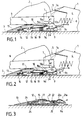
- La figure 1 est une vue en coupe verticale et longitudinale d'une butée avant suivant l'invention pourvue d'un dispositif de réglage hauteur automatique intégré dans la pédale formant palpeur de chute avant, dans le cas du maintien d'une chaussure de ski ayant une épaisseur de semelle minimale.
- La figure 2 est une vue en coupe verticale et longitudinale de la butée avant de la figure 1, adaptée au maintien d'une chaussure de ski ayant une épaisseur de semelle maximale.
- La figure 3 est une vue en coupe verticale et longitudinale partielle d'une variante d'exécution.
- Figure 1 is a vertical and longitudinal sectional view of a front stop according to the invention provided with an automatic height adjustment device integrated in the pedal forming front drop sensor, in the case of the maintenance of a ski boot having a minimum sole thickness.
- Figure 2 is a vertical and longitudinal sectional view of the front stop of Figure 1, adapted to the maintenance of a ski boot having a maximum sole thickness.
- Figure 3 is a partial vertical and longitudinal sectional view of an alternative embodiment.
Si on se réfère aux figures 1 et 2 on voit que ces figures représentent une fixation de sécurité ou "butée avant" 1 qui est destinée à maintenir l'avant d'une chaussure de ski 2 sur un ski 3. La butée avant 1 comprend un corps 4 qui est solidaire d'une embase fixée au ski. Ce corps 4 comporte, dans sa partie postérieure, une mâchoire 5 qui est destinée à maintenir le bord de la semelle 6 de la chaussure 2 qui a une épaisseur normalisée pouvant varier entre une épaisseur minimale e1 (chaussure représentée sur la figure 1) et une épaisseur maximale e2 (chaussure représentée sur la figure 2). La mâchoire de retenue 5 peut être de tout type connu et elle comporte deux ailes de retenue latérale 7 et un serre-semelle 7a qui assure la retenue de la chaussure dans le sens vertical. La mâchoire 5 peut être du type monobloc, auquel cas les deux ailes de retenue latérale 7 forment une seule pièce, ou bien encore la mâchoire 5 peut comprendre deux ailes 7 séparées, montées indépendamment à pivotement sur le corps 4 de la butée avant 1. La mâchoire 5 et plus particulièrement ses ailes de retenue latérale 7 sont sollicitées élastiquement par un mécanisme générateur d'énergie de tout type connu, logé à l'intérieur du corps 4 et qui est représenté schématiquement sur le dessin par son seul ressort 8. Ce ressort 8 est soumis à une précontrainte réglable de traction ou de compression, de manière à solliciter élastiquement les ailes de retenue latérales 7 conte la semelle 6 de la chaussure 2. La précontrainte réglable du ressort 8 détermine le seuil de déclenchement latéral de la butée avant, lorsque la jambe du skieur est soumise à un effort de torsion.If we refer to Figures 1 and 2 we see that these figures represent a safety binding or "front stop" 1 which is intended to hold the front of a
La butée avant suivant l'invention est pourvue d'un mécanisme de compensation de chute avant qui permet d'alléger la "dureté" de la butée avant, c'est-à-dire d'abaisser son seuil de déclenchement, dans le cas d'une chute avant du skieur combinée avec une torsion de sa jambe. La partie du mécanisme de compensation de chute avant qui est logée dans le corps 4 de la butée avant 1, n'a pas été représentée d'une manière détaillée et elle est indiquée schématiquement et uniquement par un basculeur 9 qui est articulé, sur le corps 4 de la butée avant 1 ou sur son embase, autour d'un axe horizontal et transversal 11. Ce basculeur 9 qui est situé dans la partie centrale, inférieure et postérieure du corps 4, comprend une branche postérieure 9a, s'étendant sensiblement horizontalement et longitudinalement vers l'arrière, et une branche antérieure 9b qui agit, comme il est indiqué par la flèche A sur les figures 1 et 2, sur le mécanisme générateur d'énergie, de manière à pouvoir faire varier le seuil de déclenchement de la fixation.The front stop according to the invention is provided with a front fall compensation mechanism which makes it possible to lighten the "hardness" of the front stop, that is to say to lower its triggering threshold, in the case of a front fall of the skier combined with a twist of his leg. The part of the front fall compensation mechanism that is housed in the
Le mécanisme de compensation de chute avant comprend également une pédale 12 qui forme un palpeur de chute avant et sur laquelle prend appui la partie antérieure de la semelle 6 de la chaussure 2. Cette pédale 12 est montée mobile sur une embase 13 fixée au ski, en arrière de la butée avant 1, et elle s'étend longitudinalement vers l'avant, en porte-à-faux, en pivotant, à sa partie postérieure, autour d'un axe horizontal et transversal 14. La pédale 12 est avantageusement réalisée en deux parties, à savoir une plaque d'appui supérieure 15, en matière plastique moulée, et une armature métallique sous-jacente 16. La plaque d'appui supérieure 15 de la pédale 12 porte, dans sa partie centrale, une plaquette anti-friction 17, par exemple en polytétrafluoroéthylène, sur laquelle s'applique effectivement la face inférieure de la semelle 6. Par ailleurs la plaque d'appui supérieure 15 de la pédale 12 comprend un prolongement antérieur 18 qui est constitué par une languette sensiblement horizontale. L'extrémité antérieure de cette languette 18 est située au-dessus et un peu en avant de l'extrémité postérieure de la branche postérieure 9a du basculeur 9. L'armature métallique inférieure 16 présente, à son extrémité postérieure, une partie transversale constituant l'axe de pivotement 14 de la pédale 12. L'armature 16 est solidaire de la plaque d'appui 15 de la pédale 12 et elle s'étend vers l'avant, en-dessous de la languette supérieure 18, sa partie extrême antérieure 16a étant située juste sous la partie extrême antérieure 18a de la languette 18, et se terminant par l'extrémité antérieure 12a de la pédale 12.The front fall compensation mechanism also includes a
La pédale 12 est sollicitée vers le haut par un ressort de compression 19 disposé entre l'embase de la pédale et la partie antérieure de l'armature 16. En position de repos soulevée qui est celle représentée sur la figure 1, la pédale 12 est immobilisée dans cette position par suite de la venue en contact d'éléments de butée prévus respectivement sur la pédale 12 et sur l'embase 13. Dans cette position de repos prédéterminée la face inférieure de la partie extrême antérieure 16a de l'armature 16 de la pédale 12 est écartée de la face supérieure de la partie extrême de la branche postérieure sous-jacente 9a du basculeur 9 d'une distance ou d'un jeu d. Ce jeu d est choisi de l'ordre de grandeur de la tolérance normalisée pour l'épaisseur de la semelle 6 de la chaussure, c'est-à-dire de la différence entre l'épaisseur maximale e2 (figure 2) et l'épaisseur minimale e1 (figure 1) qui sont admises pour la semelle 6. En pratique pour une semelle 6 d'une chaussure du type senior l'épaisseur normalisée, à l'endroit de l'embout avant de la semelle, est par exemple de 19 ± 1mm. Autrement dit les épaisseurs minimale e1 et maximale e2 de la semelle 6 sont respectivement de 18 et de 20mm. De ce fait le jeu d entre l'extrémité antérieure 12a de la semelle 12 et l'extrémité de la branche postérieure 9a du basculeur 9 est des l'ordre de 2mm.The
La pédale 12 occupe sa position de repos prédéterminée, représentée sur la figure 1, lorsqu'aucune chaussure n'est montée sur le ski. Lorsque l'avant d'une chaussure 2 ayant une semelle 6 d'épaisseur minimale e1 est engagé dans la butée avant 1, la face inférieure de la semelle 6 est tangente à la plaque anti-friction 17 alors que l'embout avant de la semelle est engagé dans la mâchoire 5 et la pédale 12 n'est pas repoussée vers le bas, à partir de sa position de repos. Toutefois si une pression verticale vers le bas est exercée sur l'avant de la chaussure, alors la pédale 12 s'abaisse contre la force de rappel du ressort 19 jusqu'au contact avec la branche 9a du basculeur 9.The
De préférence, la raideur du ressort 19 est choisie pour repousser franchement contre le serre-semelle 7a la semelle d'une chaussure de ski vide.Preferably, the stiffness of the
Ainsi qu'il est représenté sur la figure 2, lorsqu'une chaussure 2 ayant une semelle 6 d'épaisseur maximale e2 est engagée dans la butée avant 1, la semelle 6 appuie alors sur la pédale 12 suffisamment pour que le jeu d devienne nul, c'est-à-dire que l'extrémité antérieure 12a de la pédale 12 vienne juste en appuie sur l'extrémité de la branche postérieure 9a du basculeur 9. La encore cette disposition n'est pas impérative et un léger jeu d pourrait aussi subsister.As shown in FIG. 2, when a
Dans le cas d'une semelle 6 ayant une épaisseur comprise entre les épaisseurs maximale e2 et minimale e1, la pédale 12 occupe, lorsque la butée avant est enclenchée, une position intermédiaire, c'est-à-dire qu'il existe, entre l'extrémité antérieure 12a de la pédale 12 et l'extrémité de la branche postérieure 9a, un jeu réduit compris entre le jeu maximal d et un jeu nul en position de repos.In the case of a sole 6 having a thickness between the maximum thicknesses e2 and minimum thickness e1, the
Naturellement la position de repos, en hauteur, de la pédale 12 dépend de la distance entre la branche postérieure 9a du basculeur 9 et la surface supérieure du ski. Plus cette distance est faible, c'est-à-dire plus la branche postérieure 9a est proche du ski, plus l'extrémité antérieure 12a de la pédale 12 peut être basse.Naturally the rest position, in height, of the
D'après ce qui précède on voit donc que le dispositif de réglage hauteur est incorporé dans la pédale 12 formant palpeur de chute avant. Dans le cas d'une telle chute avant, le jeu entre l'extrémité avant de la pédale et la branche 9a du basculeur 9 s'annule, ou bien à cause de l'épaisseur de la semelle, ou bien sous l'effet de la poussée que la semelle exerce sur la pédale. La force exercée par la chaussure sur la pédale, indiquée par la flèche f sur les figures 1 et 2 est alors transmise au basculeur 9 par sa branche postérieure 9a, le basculeur 9 agissant alors, à l'intérieur de la butée avant 1, pour abaisser le seuil de déclenchement latéral de cette butée avant. Si la semelle 6 a l'épaisseur maximale e2, la pédale 12 exerce immédiatement, dès qu'elle est enfoncée, la force f sur la branche postérieure 9a du basculeur 9, alors qu'elle doit d'abord rattraper le jeu d, avant d'appuyer sur le basculeur 9 si la semelle a une épaisseur inférieure à l'épaisseur maximale e2, et si la pédale n'est pas déjà en appui sur la branche 9a du basculeur. Autrement dit la pédale 12 doit d'abord rattraper le jeu d prévu pour le réglage hauteur avant de pouvoir agir sur le seuil de déclenchement de la butée avant. Toutefois, il faut souligner que les efforts que la chaussure exerce sur la pédale dans le cas d'une chute avant sont nettement supérieurs à ceux qui sont en jeu dans la phase de réglage hauteur.From the above it is therefore seen that the height adjustment device is incorporated in the
Dans la variante d'exécution représentée partiellement sur la figure 3 la pédale 12 comprend, en-dessous de la plaque d'appui supérieure 15 portant la plaquette anti-friction 17, deux éléments mobiles verticalement indépendamment l'un de l'autre, à savoir une platine supérieure 21 et une platine inférieure 22. La platine supérieure 21 est solidaire de la plaque d'appui 15 et elle est articulée, a son extrémité postérieure, sur l'embase 13, autour d'un axe horizontal et transversal 23. Son extrémité antérieure 21a se trouve, en position de repos, à la distance d au-dessus de la branche postérieure 9a du basculeur 9. La platine inférieure 22 est articulée, à son extrémité postérieure, sur l'embase 13, autour d'un axe horizontal et transversal 24. Son extrémité antérieure 22a est, elle, en appui en permanence sur la branche postérieure 9a du basculeur 9. Un ressort de compression faible 25 est disposé entre les parties antérieures des deux platines 21 et 22 et il tend à les écarter mutuellement. Dans cette variante d'exécution le réglage hauteur s'effectue en faisant varier l'écartement relatif des deux platines 21 et 22. A cet effet le ressort 25 est plus faible que le ressort 8 du mécanisme générateur d'énergie. De ce fait le ressort 25 peut s'écraser seul, en premier lieu, lorsque la semelle d'une chaussure 6 est engagée dans la butée avant et prend appui sur la pédale 12, et ce, en fonction de l'épaisseur de la semelle 6. Pour une semelle 6 ayant l'épaisseur minimale e1, la platine supérieure 21 occupe la position représentée sur la figure 3, dans laquelle elle est repoussée vers le haut par le ressort 25 prenant appui sur la platine inférieure 22. Par contre si la semelle 6 a l'épaisseur maximale e2, cette semelle en prenant appui sur la plaquette anti-friction 17, provoque l'écrasement de la platine supérieure 21 sur la platine inférieure 22, si bien que son extrémité 21a vient juste au contact de la branche postérieure 9a. A partir de ce moment peut intervenir le mécanisme de compensation de chute avant.In the variant shown partially in FIG. 3, the
Claims (4)
- Safety ski binding designed to hold releasibly in place the front of a boot (2) mounted on the ski (3), comprising a body (4) attached to the ski and carrying at its rear portion a boot retention jaw (5) which incorporates two lateral retention wings (7), an energy-generating mechanism (8) housed in the body for returning the jaw elastically to a locked position, and a forward fall-compensation mechanism comprising a pedal (12) forming a forward fall-sensor mounted on the ski to the rear of the front stop (1), articulated, at its rear portion, on a seating (13) attached to the ski, about a horizontal and transverse axis (14, 23), returned upward, in a predetermined rest position, by a spring (19, 25) and having a forward extension (18) which, in the event that the skier falls forward, exerts a downward force on a movable control element, such as a rocker, belonging to the forward fall-compensation mechanism and housed in the body (4) of the front stop so as to lower a release threshold of the front stop, characterized in that the front end (12a, 21a) of the pedal (12) is, in the rest position of the pedal (12), located at a distance (d) above the movable control element (9) which approximates a standard tolerance for the thickness of the sole (6) of the boot, i.e., the allowed different between the maximum (e2) and minimum (e1) thicknesses of this sole 6.
- Safety binding according to claim 1, characterized in that the predetermined rest position of the pedal (12) is the same when no boot is mounted on the ski as when the front of a boot (2) having a sole (6) of minimal thickness (e1) is engaged in the front stop (1).
- Safety binding according to any of the preceding claims, characterized in that the pedal (12) is made in two parts, i.e., an upper support plate (15), made of molded plastic, carrying an anti-friction plate (17), and an underlying metal frame (16) attached to the support plate, having, at its rear end, a transverse part forming the pivot axis (14) of the pedal (12), the upper support plate (15) comprises a substantially horizontal forward extension (18), constituted by a substantially horizontal tongue, the frame (16) of the pedal extending forward beneath the upper tongue (18), and a compression spring (19), exerting upward stress on the pedal (12) is arranged between the seating (13) of the pedal and the front portion of the frame (16).
- Safety binding according to any one of claims 1 and 2, characterized in that the pedal (12) comprises an upper support plate (15) carrying an anti-friction plate (17) and, beneath this upper support plate, two plates vertically movable independently of one another, i.e., an upper plate (21) and a lower plate (22), the upper plate (21) is attached to the support plate (15) and it is articulated, at its rear end, to the seating (13), around a horizontal and transverse axis (23), its front end (21a) being, in rest position, at the distance d above the movable control element (9a), the lower plate (22) is articulated, at its rear end, on the seating (13) around a horizontal and transverse axis (24), and its front end (22a) is permanently supported on the rear end of the movable control element (9a) and a compression spring (25) is arranged between the front portions of the two plates (21,22) so as to space one from the other.
Applications Claiming Priority (2)
| Application Number | Priority Date | Filing Date | Title |
|---|---|---|---|
| FR9209513 | 1992-07-31 | ||
| FR929209513A FR2694206B1 (en) | 1992-07-31 | 1992-07-31 | Safety binding for ski. |
Publications (3)
| Publication Number | Publication Date |
|---|---|
| EP0580996A2 EP0580996A2 (en) | 1994-02-02 |
| EP0580996A3 EP0580996A3 (en) | 1994-05-25 |
| EP0580996B1 true EP0580996B1 (en) | 1996-05-15 |
Family
ID=9432504
Family Applications (1)
| Application Number | Title | Priority Date | Filing Date |
|---|---|---|---|
| EP93109157A Expired - Lifetime EP0580996B1 (en) | 1992-07-31 | 1993-06-08 | Safety ski binding |
Country Status (6)
| Country | Link |
|---|---|
| US (1) | US5344180A (en) |
| EP (1) | EP0580996B1 (en) |
| JP (1) | JPH06154387A (en) |
| AT (1) | ATE137984T1 (en) |
| DE (1) | DE69302636T2 (en) |
| FR (1) | FR2694206B1 (en) |
Cited By (3)
| Publication number | Priority date | Publication date | Assignee | Title |
|---|---|---|---|---|
| US5566968A (en) * | 1994-02-09 | 1996-10-22 | Salomon S.A. | Alpine ski binding element equipped with a compensation device |
| US5722681A (en) * | 1994-07-13 | 1998-03-03 | Salomon S.A. | Alpine ski binding apparatus |
| WO2002055161A1 (en) * | 2001-01-12 | 2002-07-18 | Powder Design Pty. Ltd. | Releasable boot binding |
Families Citing this family (8)
| Publication number | Priority date | Publication date | Assignee | Title |
|---|---|---|---|---|
| FR2708868B1 (en) * | 1993-08-13 | 1995-09-29 | Salomon Sa | Device for supporting a boot on a ski. |
| FR2763252B1 (en) * | 1997-05-13 | 1999-07-23 | Look Fixations Sa | SUPPORT PLATE FOR SECURITY FIXING |
| FR2803533B1 (en) * | 2000-01-07 | 2002-04-05 | Look Fixations Sa | SUPPORT DEVICE FOR THE FRONT OF A SKI SHOE ON A SKI |
| AT11239U1 (en) * | 2008-11-03 | 2010-07-15 | Atomic Austria Gmbh | SCHIBINDY WITH A POSITIONING AND FIXING DEVICE FOR THE BAKING BODY |
| FR2960440B1 (en) * | 2010-05-26 | 2013-08-02 | Salomon Sas | HIKING FIXATION FOR THE PRACTICE OF HIKING SKIING |
| FR2966747B1 (en) * | 2010-10-29 | 2013-01-11 | Salomon Sas | SECURITY FASTENING FOR THE PRACTICE OF SKIING. |
| FR2998187B1 (en) * | 2012-11-16 | 2014-12-19 | Rossignol Sa | SKI FIXING STOP AND FASTENING SYSTEM EQUIPPED WITH SUCH A FASTENING |
| CN107186525B (en) * | 2017-06-14 | 2023-08-04 | 安徽合力股份有限公司 | Clamping device for quick alignment and positioning of gearbox body |
Family Cites Families (8)
| Publication number | Priority date | Publication date | Assignee | Title |
|---|---|---|---|---|
| US4336956A (en) * | 1979-02-15 | 1982-06-29 | Vereinigte Baubeschlagfabriken Gretsch & Co. Gmbh | Safety toe unit for a ski binding |
| DE3230187C2 (en) * | 1982-08-13 | 1984-09-27 | Geze Gmbh, 7250 Leonberg | Side-release toe piece with two side jaws that can be swiveled out to the side |
| US4735435A (en) * | 1986-06-05 | 1988-04-05 | Marker Deutschland Gmbh | Front-piece for a safety ski-binding |
| FR2624387B1 (en) * | 1987-12-09 | 1990-04-06 | Salomon Sa | SECURITY FIXING FOR SKI |
| FR2624386B1 (en) * | 1987-12-09 | 1995-07-21 | Salomon Sa | SECURITY FIXING FOR SKI |
| FR2625911B1 (en) * | 1988-01-15 | 1990-06-08 | Salomon Sa | SECURITY FIXING FOR SKI |
| AT396067B (en) * | 1989-09-01 | 1993-05-25 | Tyrolia Freizeitgeraete | FRONT JAW |
| EP0506806A1 (en) * | 1989-12-18 | 1992-10-07 | Salomon S.A. | Safety binding for skis |
-
1992
- 1992-07-31 FR FR929209513A patent/FR2694206B1/en not_active Expired - Fee Related
-
1993
- 1993-06-08 DE DE69302636T patent/DE69302636T2/en not_active Expired - Fee Related
- 1993-06-08 AT AT93109157T patent/ATE137984T1/en active
- 1993-06-08 EP EP93109157A patent/EP0580996B1/en not_active Expired - Lifetime
- 1993-07-28 JP JP5186274A patent/JPH06154387A/en not_active Withdrawn
- 1993-07-29 US US08/098,831 patent/US5344180A/en not_active Expired - Fee Related
Cited By (3)
| Publication number | Priority date | Publication date | Assignee | Title |
|---|---|---|---|---|
| US5566968A (en) * | 1994-02-09 | 1996-10-22 | Salomon S.A. | Alpine ski binding element equipped with a compensation device |
| US5722681A (en) * | 1994-07-13 | 1998-03-03 | Salomon S.A. | Alpine ski binding apparatus |
| WO2002055161A1 (en) * | 2001-01-12 | 2002-07-18 | Powder Design Pty. Ltd. | Releasable boot binding |
Also Published As
| Publication number | Publication date |
|---|---|
| DE69302636D1 (en) | 1996-06-20 |
| JPH06154387A (en) | 1994-06-03 |
| EP0580996A2 (en) | 1994-02-02 |
| ATE137984T1 (en) | 1996-06-15 |
| FR2694206B1 (en) | 1994-09-02 |
| FR2694206A1 (en) | 1994-02-04 |
| US5344180A (en) | 1994-09-06 |
| EP0580996A3 (en) | 1994-05-25 |
| DE69302636T2 (en) | 1996-11-28 |
Similar Documents
| Publication | Publication Date | Title |
|---|---|---|
| EP0580996B1 (en) | Safety ski binding | |
| EP0530449B1 (en) | Device for modifying the pressure distribution of a ski on its sliding surface | |
| CH654485A5 (en) | SECURITY FIXING FOR SKIING. | |
| EP0025747B1 (en) | Toe binding for ski | |
| EP1616604A1 (en) | Fixation device for a boot to a sports article with separated elastic returning means | |
| FR2537442A1 (en) | SECURITY FASTENING FOR SKI | |
| EP0692288B1 (en) | Alpine ski-binding | |
| EP0653231B1 (en) | Binding element for skis | |
| EP0130864B1 (en) | Safety ski binding | |
| EP0674925B1 (en) | Skibinding | |
| EP2552559A1 (en) | Binding for the practice of skiing | |
| EP0658360A1 (en) | Intermediate device between a ski and the binding | |
| FR2560778A1 (en) | SECURITY FIXING FOR AUTOMATIC COMPENSATION SKI | |
| EP0634196B1 (en) | Binding element for alpine skis | |
| FR3096651A1 (en) | Automatic pedal for cycle | |
| EP0068921B1 (en) | Binding-device for holding the foot of a skier upon a ski, comprising a ski-boot and a toe-binding | |
| CH659952A5 (en) | SECURITY FIXING FOR SKIING. | |
| FR2631244A1 (en) | Front jaw equipping safety bindings for skis | |
| EP0700699B1 (en) | Ski binding | |
| EP0856337B1 (en) | Safety binding on the topsurface of a skiboot | |
| FR2627096A1 (en) | ALPINE SKI SECURITY FASTENING | |
| FR2687927A1 (en) | DEVICE FOR SUPPORTING A SHOE ON A SKI, ASSOCIATED WITH A SAFETY FRONT STOP. | |
| FR2739301A1 (en) | ELEMENT AND RETAINING ASSEMBLY OF A SHOE ON A BOARD OF SLIDING | |
| FR3080599A1 (en) | AUTOMATIC BICYCLE PEDAL | |
| FR2794028A1 (en) | Releasable binding for snowboard boot has hook levers engaging sole recesses and spring biased into place |
Legal Events
| Date | Code | Title | Description |
|---|---|---|---|
| PUAI | Public reference made under article 153(3) epc to a published international application that has entered the european phase |
Free format text: ORIGINAL CODE: 0009012 |
|
| AK | Designated contracting states |
Kind code of ref document: A2 Designated state(s): AT CH DE IT LI |
|
| PUAL | Search report despatched |
Free format text: ORIGINAL CODE: 0009013 |
|
| AK | Designated contracting states |
Kind code of ref document: A3 Designated state(s): AT CH DE IT LI |
|
| 17P | Request for examination filed |
Effective date: 19940614 |
|
| 17Q | First examination report despatched |
Effective date: 19951018 |
|
| GRAH | Despatch of communication of intention to grant a patent |
Free format text: ORIGINAL CODE: EPIDOS IGRA |
|
| GRAA | (expected) grant |
Free format text: ORIGINAL CODE: 0009210 |
|
| AK | Designated contracting states |
Kind code of ref document: B1 Designated state(s): AT CH DE IT LI |
|
| PG25 | Lapsed in a contracting state [announced via postgrant information from national office to epo] |
Ref country code: IT Free format text: LAPSE BECAUSE OF FAILURE TO SUBMIT A TRANSLATION OF THE DESCRIPTION OR TO PAY THE FEE WITHIN THE PRESCRIBED TIME-LIMIT;WARNING: LAPSES OF ITALIAN PATENTS WITH EFFECTIVE DATE BEFORE 2007 MAY HAVE OCCURRED AT ANY TIME BEFORE 2007. THE CORRECT EFFECTIVE DATE MAY BE DIFFERENT FROM THE ONE RECORDED. Effective date: 19960515 |
|
| REF | Corresponds to: |
Ref document number: 137984 Country of ref document: AT Date of ref document: 19960615 Kind code of ref document: T |
|
| REG | Reference to a national code |
Ref country code: CH Ref legal event code: NV Representative=s name: CABINET ROLAND NITHARDT CONSEILS EN PROPRIETE INDU |
|
| REF | Corresponds to: |
Ref document number: 69302636 Country of ref document: DE Date of ref document: 19960620 |
|
| PLBE | No opposition filed within time limit |
Free format text: ORIGINAL CODE: 0009261 |
|
| STAA | Information on the status of an ep patent application or granted ep patent |
Free format text: STATUS: NO OPPOSITION FILED WITHIN TIME LIMIT |
|
| 26N | No opposition filed | ||
| PGFP | Annual fee paid to national office [announced via postgrant information from national office to epo] |
Ref country code: CH Payment date: 19970926 Year of fee payment: 5 |
|
| PGFP | Annual fee paid to national office [announced via postgrant information from national office to epo] |
Ref country code: AT Payment date: 19980610 Year of fee payment: 6 |
|
| PG25 | Lapsed in a contracting state [announced via postgrant information from national office to epo] |
Ref country code: LI Free format text: LAPSE BECAUSE OF NON-PAYMENT OF DUE FEES Effective date: 19980630 Ref country code: CH Free format text: LAPSE BECAUSE OF NON-PAYMENT OF DUE FEES Effective date: 19980630 |
|
| PGFP | Annual fee paid to national office [announced via postgrant information from national office to epo] |
Ref country code: DE Payment date: 19980727 Year of fee payment: 6 |
|
| REG | Reference to a national code |
Ref country code: CH Ref legal event code: PL |
|
| PG25 | Lapsed in a contracting state [announced via postgrant information from national office to epo] |
Ref country code: AT Free format text: LAPSE BECAUSE OF NON-PAYMENT OF DUE FEES Effective date: 19990608 |
|
| PG25 | Lapsed in a contracting state [announced via postgrant information from national office to epo] |
Ref country code: DE Free format text: LAPSE BECAUSE OF NON-PAYMENT OF DUE FEES Effective date: 20000503 |