EP0580376B1 - Bildverarbeitungsverfahren zur Verringerung der Deckung von Markierungsmaterial in Druckprozessen - Google Patents
Bildverarbeitungsverfahren zur Verringerung der Deckung von Markierungsmaterial in Druckprozessen Download PDFInfo
- Publication number
- EP0580376B1 EP0580376B1 EP93305627A EP93305627A EP0580376B1 EP 0580376 B1 EP0580376 B1 EP 0580376B1 EP 93305627 A EP93305627 A EP 93305627A EP 93305627 A EP93305627 A EP 93305627A EP 0580376 B1 EP0580376 B1 EP 0580376B1
- Authority
- EP
- European Patent Office
- Prior art keywords
- pixel
- pixels
- marking material
- separation
- turned
- Prior art date
- Legal status (The legal status is an assumption and is not a legal conclusion. Google has not performed a legal analysis and makes no representation as to the accuracy of the status listed.)
- Expired - Lifetime
Links
Images



Classifications
-
- H—ELECTRICITY
- H04—ELECTRIC COMMUNICATION TECHNIQUE
- H04N—PICTORIAL COMMUNICATION, e.g. TELEVISION
- H04N1/00—Scanning, transmission or reproduction of documents or the like, e.g. facsimile transmission; Details thereof
- H04N1/46—Colour picture communication systems
- H04N1/50—Picture reproducers
-
- G—PHYSICS
- G06—COMPUTING OR CALCULATING; COUNTING
- G06K—GRAPHICAL DATA READING; PRESENTATION OF DATA; RECORD CARRIERS; HANDLING RECORD CARRIERS
- G06K15/00—Arrangements for producing a permanent visual presentation of the output data, e.g. computer output printers
- G06K15/02—Arrangements for producing a permanent visual presentation of the output data, e.g. computer output printers using printers
- G06K15/10—Arrangements for producing a permanent visual presentation of the output data, e.g. computer output printers using printers by matrix printers
- G06K15/102—Arrangements for producing a permanent visual presentation of the output data, e.g. computer output printers using printers by matrix printers using ink jet print heads
-
- G—PHYSICS
- G06—COMPUTING OR CALCULATING; COUNTING
- G06K—GRAPHICAL DATA READING; PRESENTATION OF DATA; RECORD CARRIERS; HANDLING RECORD CARRIERS
- G06K2215/00—Arrangements for producing a permanent visual presentation of the output data
- G06K2215/0002—Handling the output data
- G06K2215/0062—Handling the output data combining generic and host data, e.g. filling a raster
- G06K2215/0071—Post-treatment of the composed image, e.g. compression, rotation
- G06K2215/0074—Depleting the image
-
- G—PHYSICS
- G06—COMPUTING OR CALCULATING; COUNTING
- G06K—GRAPHICAL DATA READING; PRESENTATION OF DATA; RECORD CARRIERS; HANDLING RECORD CARRIERS
- G06K2215/00—Arrangements for producing a permanent visual presentation of the output data
- G06K2215/0082—Architecture adapted for a particular function
- G06K2215/0094—Colour printing
Definitions
- This invention relates to an image processing method for reducing the amount of marking material required to print a colored image, to avoid problems common to the use of excessive amounts of ink.
- Full color printing has become a desired goal of office products.
- One type of full color printer which has significant potential for fulfilling such a goal is the ink jet printer.
- a reservoir of liquid ink is connected to an ink output orifice via a capillary tube.
- a heater element is provided, responsive to an on/off or binary printing signal.
- the heater element rapidly heats ink in the capillary tube adjacent thereto to a gaseous state, producing a pressure differential which expels a droplet of ink from the orifice, directing the droplet to a sheet of receiving material, such as paper.
- Color printing is accomplished by providing multiple layers or separations of ink on the page.
- colors are provided by subtractive combinations of cyan, magenta and yellow inks.
- To print black a combination of equal amounts of cyan, magenta and yellow is printed, or a fourth black ink is used as a substitute.
- Undercolor removal a well known process in the printing arts, can be used to print a single layer of black ink as a substitute for the combination of equal amounts of cyan, magenta and yellow.
- J.A.C. Yule Principles of Color Reproduction , (John Wiley & Sons, Inc., New York, 1967), pages 294-327.
- Other full color printing processes may use dry powder or liquid toners.
- a problem of ink jet printers is that the liquid inks used have a finite drying time, which tends to be somewhat longer than desirable. Further, the drying time of any particular area is at least partly a function of the amount of ink deposited on that area. While satisfactory drying times are possible with black-only or single separation printing, once multiple separations are required, the large amount of liquid on the page causes the problems of ink puddling or pooling, bleeding to adjacent image areas, and flow through to the back side of the receiving material. Paper cockle is also a problem due to saturation of the paper receiving material and subsequent rapid drying. Particularly, problems are noted in the printed image at high ink coverage areas, and high coverage areas where high contrast image edges occur. While certain materials variations, such as different inks or special papers may resolve some of these problems, each brings its own distinct problems to the process. While special treated papers optimized for ink jet use are possible, plain papers are preferred from cost and convenience standpoints.
- ink coverage refers to the number of ON pixels in a region for all the separations, divided by the total number of pixels in the the region in one separation. Without undercolor removal, typical full color image may require ink coverage in the range of 200-300%. With undercolor removal, maximum ink coverage may be down to 200%, but no lower. Additionally, it would be highly desirable for the process to operate irrespective of image content, or on the separation binary bitmaps without further image information.
- ink jet printing has a notable problem with the case of high ink coverage
- other printing processes which are printed on a pixel by pixel basis also have problems with excessive marking material.
- electrophotographic printing methods using a pixel by pixel printing process for forming a latent image for development by dry or liquid toner marking materials can suffer from excessive marking material, evidenced by sheet cockling, and curling caused by differential shrinkage of toner and paper in the printing process.
- the image data is first error diffused from 8 bits per pixel per separation to 4 bits pixel per separation. Then, for each pixel, a count of up to 4 drops of each dye loading is computed, for each separation. There are multiple choices, ranked in order of total ink coverage. If the highest coverage choice exceeds the maximum allowable coverage, the separation with highest coverage is changed to use a lower coverage value for the same gray level, if possible. If it is not possible to stay at the same gray level, the gray level for that separation is dropped by one, and the error passed on to neighbors. The process iterates until the total ink coverage is as low as required Pixels within the 2 x 2 block are assigned values (0 or 1) by proceeding around the block in clockwise order, and filling in pixels in order.
- the high dye load pixels are turned on, then the medium, then the low.
- first black is turned on, until there are no more black pixels of that dye loading, then the next pixels in the cycle are cyan, until there are no more cyan required, then magenta, and yellow, and then the next dye load group.
- US-A 4,999,646 to Trask teaches limiting coverage to 100% coverage (by the above definition of coverage), or perhaps between 100 and 200% coverage (if 100% corresponds exactly to no white spaces on a page) , owing to the circular shape and overlap of print dots. Coverage is limited by using 2x2 super pixels and assigning each one drop per pixel in a combination that depends on the color required. Assuming one bit per separation input with full undercolor removal, there are eight possible colors that could be requested (including white). In order to reduce patterning due to the multiple swaths, two passes are used, each of a checkerboard pattern of pixels (the two passes being offset to provide full coverage). The two pass process allows ink to dry between passes.
- US-A-4,595,948 teaches a multicolor ink jet recording apparatus having a means for preventing blurring of ink.
- the values of a set of 8 bit color signals are used to select pregenerated templates, that have marking material reduction built into them.
- An object of the invention is to provide a method for reducing the amount of marking material used in an printer to reduce marking materials coverage in full color images to less than 200%, while minimally affecting the appearance of the color image.
- the present invention provides a method according to claim 1 and a device according to claim 9.
- the method of reducing marking material coverage includes the step of making a determination of marking material coverage for an area of the image, based on the number of pixels within the given area that are turned ON. Subsequently, if a determination is made that too much marking material will be printed within the given area, a fraction of the pixels in the area are turned off in each separation to reduce the amount of marking material that will be used for the given area. To prevent artifacts from occurring in the pixel reduction step, a processing path through each given area is used which tends to randomize the turn off effect.
- the method of determining marking material coverage within a given area may include the steps of: identifying density values of a set of pixels within a subset of the given area of the image for each separation; using the pixel values in the subset as addresses to a Look Up Table (LUT), each address entry in the LUT having associated with it a data entry representing a predicted amount of marking material coverage that will be printed within the subset of the area, given the pixel values in the given area.
- LUT Look Up Table
- the process is repeated for all the subsets within the given area, and the address values are summed to determine the amount of marking material resulting from each separation.
- the marking material coverage value for each separation are summed to determine the total amount of ink that will be used.
- a second condition may be applied to the turn OFF decision, based on whether, for all the separations, the same pixel has been turned off, to prevent the case of no color at the particular position in the image.
- the method of avoiding patterns which might appear as image processing artifacts includes the step of processing pixels within a given area in an order that tends to prevent moire patterns from arising. Accordingly, a path of processing pixels in accordance with the previously described turn OFF determination is selected so that, for a uniform area and a constant fraction of pixels turned OFF, the turned OFF pixel is at a different position in each scan line.
- One useful path is an area filling curve.
- the present invention is directed to a method of changing each separation in a color image in a manner that reduces the number of ON pixels in each separation, and accordingly the marking material deposited over an image.
- a turnoff ratio determination is made based on the multiple separation image. The same fraction of pixels is turned off in each separation, so that the overall hue of the image is not shifted. Interestingly, the brightness of color changes little in the image processed by the inventive method, suggesting that the excess deposited marking material did not contribute to color brightness.
- the reduction of pixels is accomplished in a manner avoiding patterns, to reduce moire. The reduction in the number of ON pixels only occurs in areas where there is too much marking material.
- FIG. 1 a basic functional block diagram for a system for carrying out the present invention is shown in Figure 1.
- a plurality of video inputs 10c, 10y, 10m, and 10k, each representing one of the cyan, magenta, yellow or black separations (B N (x,y)) of image B(x,y) are directed into the ink coverage reduction system Since the process of the system is mostly redundant for each separation, initially only the cyan bitmap B C (x,y) will be described.
- Bitmap B C (x,y) is a binary bitmap in this system, defined along fast (x-axis) and slow scan (y-axis) axes, describing the image in terms of 1 bit pixels arrayed in scan lines.
- Each pixel is an image signal, which may be said to have a condition or image state, which describes for a binary pixel whether a print dot will be made at the output or not. This may also be equated to whether the pixel is ON or OFF, 1 or 0.
- bitmap B C (x,y) is directed initially to a one byte (8 bit) latch 12, which stores eight one bit pixel values in order 1 to 8.
- This 8 bit stored binary string which represents the bitmap image in an 8 pixel x 1 scan line portion of the given area, is used as an address to access a 256 entry look up table (LUT) 14.
- LUT look up table
- the data stored at each of addresses 16 in the look up table 14 represents ink coverage values 18, for the 8 pixel area stored at latch 12. It will no doubt be appreciated that many of these ink coverage values are the same, as shown by the demonstration of address 00000001 and address 00000010, which each have ink coverage values of 1. Should ink coverage be non-linear in character, because, for example, the ink jet device tends to deposit more or less ink when operated in certain image formations, then such non-linearity may be accounted for in loading the LUT 14 values.
- I C (x,y) representing predicted ink coverage in an 8 pixel x 1 scan line.
- the output of accumulator 22 is a value m , the predicted or measured ink coverage value for each separation of the given area of the image.
- the values of I N (y), measured for each of the cyan, magenta, yellow and black separation bitmaps, are added to derive a value m , which is the predicted or measured ink coverage value for the given area of the image. It is possible that some colors bleed more than others; if so, some separations might be weighted more heavily in the summation.
- An 8 pixel by 8 scan line block for the given area has been selected for processing convenience, and because it reflects a useful size for the ink reduction determination. If the area is too large, the ink coverage variations will be averaged in the reduction determination, giving low ink coverage indications when portions within the large area exceed the maximum desirable ink coverage.
- the choice of area or window size is a compromise between the precision with which coverage can be measured (the larger the area the more possible ink coverage levels) and the accuracy of its measurement.
- One way of increasing the precision without reducing the locality is to use a weighted sum (more heavily weighting the center) to find the coverage near the the center of the window. This would work best for finding the coverage in the neighborhood of a single pixel.
- coverage was determined using an unweighted average over the 8 x 8 area, as, if this area should prove satisfactory, it would be much less expensive to compute.
- the 8 x 8 window allows for greater efficiency of implementation as it uses complete bytes. Computing coverage in an 8 x 8 window, always aligned on a 4 bit boundary can be done efficiently using small tables.
- a 256 entry table may be indexed by the contents of the scanline covered by the window, for each scanline in the window, summing the results; when it is not byte-aligned, two 16-element tables for may be indexed for each each scanline, to compute: cl[p1&0xf] + cr[p2>>4], where p1 and p2 are the values in the image beneath the window; cl and cr are appropriately initialized tables having 16 entries giving bit counts.
- This expression refers to the use of the low order four bits of p1 to index into table cl, and the high order bits of p2 are used to index into table cr.
- Value m is used at ON/OFF logic 24 to apply the turn off ratio d / m to each separation of the image, where d represents the maximum desired number of pixels ON in an area, and d / m , therefore represents a ratio reflecting that d pixels out of every m pixels in a separation bitmap should be left on. It may be convenient to compare ratio d / m to 1, where a ratio greater than 1 indicates no need to turn off any pixels. It will be assumed hereinafter that such a comparison has taken place and has indicated a value of d / m less than 1.
- ON/OFF logic 38 may include a counter, which counts from 0 to m by increments of d for each pixel on in B c (x,y). Upon reaching or exceeding m, an output representing an ON signal is produced, to indicate that the current pixel should be left on. This will be further illustrated hereinafter.
- the presence or absence of a print dot in each separation can be taken as a predicted amount of ink.
- a predicted value of ink coverage can be made.
- the measured amount of ink is a function of the gray level value of the pixel, or the percentage of the maximum ink value deposited at a pixel in the image.
- the "turn OFF ratio" or ON/OFF ratio of d / m would result in a periodic pattern, which, when imposed on a halftone pattern probably existing in B C (x,y), would result in undesirable moire patterns in the reproduction of the image. Accordingly, one method of alleviating this problem is to randomize the application of the turn OFF ratio to the bitmap. However, it is also desirable that the determination of ON/OFF be made with knowledge of the determination for adjacent pixels, so that the application of the turn OFF ratio can be applied uniformly through the given area.
- Figures 2a-e where Figure 2a shows the usual method of progressing through a bitmap, processing pixels 1 to n, from scan line 1 to scan line k, Figures 2b-e show other processing orders (shown for only 4 x 4 areas, as will be explained below), with a preferred processing order being the area filling curve of Figure 2e. It will no doubt be appreciated that other processing orders are possible, which process pixels in an order that is relatively random with respect to common halftone patterns, and retains dependence on adjacent pixels.
- Ordering of pixels is accomplished by storing a 4 x 4 set of pixels for which m has been determined in memory 25, and subsequently reading the values of B c (x,y) out of memory with processing order control 26, which reorders pixels of B c (x,y) in accordance with the selected pixel order function.
- a logical process is employed implementing the determined turn OFF ratio.
- the fraction of pixels to be left ON is the ratio of the desired coverage to the measured coverage. This can be exactly retained as a rational number, d / m .
- f initially set to zero, is the (fractional) number of pixels that should have been turned on since the last one was turned on, or alternatively the fraction of the way to the next pixel that should be turned on.
- the initial setting of f to zero is arbitrary, as over an entire image the initial value of f is of no consequence. To reduce inter-separation correlations it may be advantageous to use various values between 0 and m for the initial settings of the control variable for different separations.
- the function is reordered into the original image order as B CON/OFF (x,y), which is a mask representing the turn OFF function.
- white pixel prevention logic is provided, to prevent the occurrence of a corresponding pixel in every separation from being turned OFF, which might allow white or background show through. Assuming 100% coverage is acceptable, totally white pixels should not be introduced into the image.
- a set of ON/OFF conditions is created for a 4 x 4 area of the image, reducing the number of ON pixels in that area in accordance with the determining turn OFF ratio, B' CON/OFF (x,y).
- This set of values is then used as on input to a masking logic 42, which uses B' CON/OFF (x,y) in altering the bitmap B C (x,y) at block 42 from which the now adjusted image B' C (x,y)is directed to the printer controller.
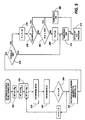
- Figure 3 presents the process steps in the described embodiment, which generally include the steps of 110) measuring potential ink coverage in separation N of B(x,y); 130) determining the location in the image of pixels which should be turned OFF in accordance with the turn OFF ratio; 140) comparing each separation with the others to prevent corresponding pixels in each separation from being all turned OFF; 160) setting pixels in the separation of B(x,y) OFF and 170) outputting the adjusted image to a print controller.
- the method of ink coverage measurement includes the steps of 200) for the cyan bitmap B C (x,y) initializing the scan line and pixel values to a starting value (here, 0); 202) storing a first subset of pixels (here, n) from a first scan line at latch 12; 220) using the stored n bit value to access a memory location in LUT 14; 230) retrieving an ink coverage value I C (y) for the set of pixels; and 240) storing the set ink coverage value I C (y) in memory 20.
- the scan line value is incremented so that the process may be repeated for the next subset of pixels from a second scan line. If a desired area of coverage, here an 8 scan line region has been examined, the test of step 260 is met, the scan line value is reset to 0 and at step 270, the pixel value is set for the next subset of pixels in each scan line. If the test at step 260 is met, the ink coverage value m C for the 8 x 8 area in the separation is determined by a standard summing function, indicated by the equation of step 280. At step 290, m c , m m , m y , m k are summed to derive a value of m for the given area of the image.
- Steps 340 and 350 together store the pixel values of B C (x,y) in a memory 25.
- pixels are read out of memory 25 by reorder processor 26 in order F C (x,y), to avoid moire.
- F C (x,y) may vary from separation to separation, if required to avoid moire
- bitmap B C (x,y) is examined to determine whether the current pixel is ON or OFF. If it is off, the pixel remains off (step 372), and the next pixel is processed (step 374). If bitmap B C (x,y) is examined at step 370 and the current pixel is ON, at step 376, f is incremented by the value d . At step 378, the "count" is compared to 1. The count represents a running sum of other separations that are turned ON at the current x,y position. If the count equals 1, then only the current separation is turned ON, and accordingly, to avoid a white space, the current pixel should be turned ON at step 380.
- f is compared to m . If f is less than or equal to m , then the pixels remains ON, at step 380. If f is not less than or equal to m , then f is decremented by m at step 384, and the pixel is turned OFF at step 372.
- each separation turn off function B NON/OFF (x,y) (represented for the purpose of this figure as B c , B m , B y , B k ) is ANDed with the others (step 420) to derive cm, cy, ck, my, mk, yk, which are then ORed together to derive a determination SEP ON/OFF .
- Step 440 If SEP ON/OFF is greater than 0 (Step 440), then at least one of the separations is to be turned ON, and no action is required. B CON/OFF (x,y) is directed to an output at step 450. However if SEP ON/OFF is equal to 0 (Step 440), then B ON/OFF (x,y) is turned ON. This is a rather simplistic solution, since undoubtedly, the choice ot separation which is turned ON in white pixel prevention should be alternated among the separations that were turned OFF Otherwise, if, for example, the cyan separation is always processed first, then the image make be skewed with a greater amount of cyan than desired.
- ink coverage can be measured by reference to the bitmap of the image, and that by a comparison of measured ink coverage with desired ink coverage, an ON/OFF ratio can be determined and applied to the pixels in the separations of the image to reduce ink coverage.
- the determination is made in a manner that minimizes moire, and preferably, makes the determination of OFF or ON in any single separation with knowledge about the state of the corresponding pixels in other separations.
Landscapes
- Engineering & Computer Science (AREA)
- Physics & Mathematics (AREA)
- Multimedia (AREA)
- General Engineering & Computer Science (AREA)
- General Physics & Mathematics (AREA)
- Theoretical Computer Science (AREA)
- Mathematical Physics (AREA)
- Signal Processing (AREA)
- Ink Jet (AREA)
- Record Information Processing For Printing (AREA)
- Editing Of Facsimile Originals (AREA)
- Dot-Matrix Printers And Others (AREA)
- Color, Gradation (AREA)
- Ink Jet Recording Methods And Recording Media Thereof (AREA)
- Color Image Communication Systems (AREA)
Claims (11)
- Verfahren zum Verarbeiten eines Farbbildes für das Drucken, um die Menge des dafür verwendeten Markierungsmaterials zu reduzieren, wobei sich das Farbbild aus mehreren Auszügen aus Markierungsmaterial zusammensetzt, wobei ein Markierungsmaterialgesamtdeckungswert in einem bestimmten Bereich innerhalb des Bildes vorausgesagt wird und der vorausgesagte Markierungsmaterialgesamtdeckungswert in Antwort auf einen Vergleich mit einem gewünschten maximalen Wert reduziert wird, dadurch gekennzeichnet, daß jeder Auszug durch eine Bitmap aus 1-Bit-Pixeln mit jeweils einem Pixelwert definiert wird, die in einer Matrix aus Scanzeilen angeordnet sind, wobei das Verfahren umfaßt:Messen der entsprechenden Markierungsmaterialdeckung (mc, mm, my, mk) in dem Bereich in jeder Auszugsbitmap,Summieren der Markierungsmaterialdeckung der Auszüge in dem Bereich, um die vorausgesagte Markierungsmaterialdeckung (m) zu bestimmen,Vergleichen der gewünschten Markierungsmaterialdeckung (d) mit der vorausgesagten Markierungsmaterialgesamtdeckung (m), um ein ON/OFF-Verhältnis (d/m) zu erhalten, wobei das ON/OFF-Verhältnis (d/m) die Anzahl der OFF zu schaltenden Pixel unabhängig von deren Pixelwert in bezug auf die Anzahl der Pixel in einem Auszug angibt,Setzen der Anzahl der Pixel unabhängig von deren Zustand auf OFF innerhalb einer größeren Anzahl von Pixeln in einem Auszug in Übereinstimmung mit dem OFF-Schaltverhältnis, wobei für jedes Pixel in dem Auszug in Übereinstimmung mit einer vom Zustand der zuvor verarbeiteten Pixel abhängigen Funktion bestimmt wird, ob dieses Pixel OFF geschaltet werden soll, undAusgeben der Auszugsbitmap zu einem Druckcontroller.
- Verfahren nach Anspruch 1, dadurch gekennzeichnet, daß der Schritt zum Messen der Markierungsmaterialdeckung folgende Teilschritte umfaßt:Eingeben der Pixelwerte eines Satzes von k Pixeln aus einer einzelnen Scanzeile aus Pixeln in einen Latchspeicher (12), wobei k eine ganze Zahl von Pixeln angibt,Vorsehen einer vorgeladenen Nachschlagetabelle (14) mit einem Satz von k Bit-adressen, wobei jede Adresse Dateneinträgen einschließlich einer möglichen Kombination von Markierungsmaterialdeckungswerten für einen Satz von k Pixeln entspricht,Speichern der Markierungsmaterialdeckungswerte aus der Nachschlagetabelle (14) in einem Speicher (20) für jeden Satz von k Pixelwerten für einen Satz von Scanzeilen, undSummieren für das Bild der Markierungsmaterialdeckungswerte für jeden Auszug in dem Bereich eines Satzes von k Pixelwerten in einem Satz von Scanzeilen.
- Verfahren nach Anspruch 1 oder 2, dadurch gekennzeichnet, daß der Schritt zum OFF-Setzen einer Anzahl von Pixeln in der Bitmap unabhängig von deren Zustand in einer größeren Anzahl von Pixeln in einem Auszug in Übereinstimmung mit dem OFF-Schaltverhältnis folgende Teilschritte umfaßt:Inkrementieren des Wertes eines Zählers (38) um eine vorbestimmte auf das OFF/ON-Verhältnis bezogene Größe, wobei das Erhöhen des Zählwertes die Wahrscheinlichkeit erhöht, daß das Pixel OFF gesetzt wird,Vergleichen des Zählwertes mit einer Bezugsgröße, um zu bestimmen, ob das Pixel OFF gesetzt werden soll,wenn bestimmt wurde, daß das Pixel OFF geschaltet werden sollte, Rücksetzen des Zählers (38), so daß die Wahrscheinlichkeit für das OFF-Schalten des nächsten Pixels herabgesetzt wird,Durchführen eines logischen UND-Prozesses zwischen dem Pixelwert und der ON/OFF-Bestimmung.
- Verfahren nach wenigstens einem der Ansprüche 1 bis 3, dadurch gekennzeichnet, daß der Schritt zum Vergleichen der gewünschten Markierungsmaterialdeckung mit der gemessenen Markierungsmaterialdeckung, um ein OFF-Schaltverhältnis zu erhalten, das die Anzahl der OFF zu schaltenden Pixel in einer größeren Anzahl von Pixeln in einem Auszug angibt, den folgenden zusätzlichen Schritt umfaßt:
Bestimmen der Position von Pixeln im Bild, die in Übereinstimmung mit dem OFF-Schaltverhältnis OFF geschaltet werden sollen. - Verfahren nach Anspruch 4, dadurch gekennzeichnet, daß der Schritt zum Bestimmen der Position der Pixel im Bild, die in Übereinstimmung mit dem OFF-Verhältnis OFF geschaltet werden sollen, den folgenden Teilschritt umfaßt:
Verarbeiten der Pixel in dem Bereich in einer vorbestimmten Reihenfolge. - Verfahren nach Anspruch 5, dadurch gekennzeichnet, daß die Verarbeitungsreihenfolge dem Pfad einer Raumfüllkurve durch jedes Pixel in dem Bereich entspricht.
- Verfahren nach Anspruch 4, dadurch gekennzeichnet, daß der Schritt zum Bestimmen der Position von Pixeln im Bild, die in Übereinstimmung mit dem OFF-Verhältnis OFF geschaltet werden sollen, folgenden zusätzlichen Schritt umfaßt:
Vergleichen des Zustands der entsprechenden Pixel in jeder Auszugsbitmap und ON-Schalten von wenigstens einem Pixel, wenn entsprechende OFF geschaltete Pixeln festgestellt werden. - Verfahren nach wenigstens einem der Ansprüche 1 bis 7, dadurch gekennzeichnet, daß das Verfahren zum Verarbeiten eines Farbbildes für das Drucken durch einen Tintenstrahldrucker verwendet wird, um die dafür verwendete Tinte zu reduzieren.
- Vorrichtung zum Verarbeiten eines Farbbildes für das Drucken, um die Menge des dafür verwendeten Markierungsmaterials zu reduzieren, wobei sich das Farbbild aus mehreren Auszügen aus Markierungsmaterial zusammensetzt, wobei ein Markierungsmaterialgesamtdeckungswert in einem bestimmten Bereich innerhalb des Bildes vorausgesagt wird und der vorausgesagte Markierungsmaterialgesamtdeckungswert in Antwort auf einen Vergleich mit einem gewünschten maximalen Wert reduziert wird, wobei jeder Auszug durch eine Bitmap aus 1-Bit-Pixeln mit jeweils einem Pixelwert definiert wird, die in einer Matrix aus Scanzeilen angeordnet sind, wobei die Vorrichtung umfaßt:eine Einrichtung zum Voraussagen der Markierungsmaterialdeckung eines Bereichs im Ausgabebild in Abhängigkeit vom Eingabebild, und gekennzeichnet durcheine Einrichtung zum Bestimmen des Verhältnisses der OFF zu schaltenden Pixel unabhängig von deren Zustand in Abhängigkeit von der gewünschten Markierungsmaterialdeckung und der vorausgesagten Markierungsmaterialdeckung,eine Positionierungseinrichtung zum Bestimmen der Positionen der Pixel in einem Auszug des Bildes, die in Übereinstimmung mit dem OFF-Schaltverhältnis OFF geschaltet werden sollen,eine OFF-Schaltbestimmungseinrichtung zum Bestimmen, ob ein Pixel in Übereinstimmung mit dem OFF-Schaltverhältnis OFF geschaltet werden soll,eine Logikschaltung, die als Eingabe die Pixelwerte in jedem Auszug sowie das OFF-Schaltverhältnis aus der OFF-Schaltbestimmungseinrichtung nimmt und als Ausgabe einen Pixelwert für ein Bild mit reduziertem Markierungsmaterial ausgibt, wobei für jedes Pixel im Auszug in Übereinstimmung mit einer vom Zustand von zuvor verarbeiteten Pixeln abhängigen Funktion bestimmt wird, ob dieses Pixel OFF geschaltet werden soll, undeiner Ausgabeeinrichtung zum Ausgeben der Auszugsbitmap zu einem Druckcontroller.
- Vorrichtung nach Anspruch 9, wobei die OFF-Schaltbestimmungseinrichtung zum Bestimmen, ob ein Pixel in Übereinstimmung mit dem OFF-Schaltverhältnis OFF geschaltet werden soll, umfaßt:einen Zähler (18), der einen Zählwert aufrechterhält, der mit jedem verarbeiteten Pixel um eine auf das OFF-Schaltverhältnis bezogene vorbestimmte Größe inkrementiert wird, wobei das Erhöhen des Zählwertes die Wahrscheinlichkeit erhöht, daß das Pixel OFF gesetzt wird,eine Vergleichereinrichtung zum Vergleichen des Zählwertes mit einer Bezugsgröße, um zu bestimmen, ob das Pixel OFF gesetzt werden soll, undeine Einrichtung zum Rücksetzen des Zählers (38), so daß die Wahrscheinlichkeit für das OFF-Schalten des nächsten Pixels herabgesetzt wird.
- Vorrichtung nach Anspruch 9, wobei die OFF-Schaltbestimmungseinrichtung zum Bestimmen, ob ein Pixel in Übereinstimmung mit dem OFF-Schaltverhältnis OFF geschaltet werden soll, umfaßt:
eine Vergleichereinrichtung zum Vergleichen des Zustands der entsprechenden Pixel in jeder Auszugsbitmap und zum ON-Schalten von wenigstens einem Pixel, wenn festgestellt wird, daß entsprechende Pixel OFF geschaltet wurden.
Applications Claiming Priority (2)
| Application Number | Priority Date | Filing Date | Title |
|---|---|---|---|
| US917643 | 1992-07-23 | ||
| US07/917,643 US5515479A (en) | 1992-07-23 | 1992-07-23 | Image processing method to reduce marking material coverage in printing processes |
Publications (2)
| Publication Number | Publication Date |
|---|---|
| EP0580376A1 EP0580376A1 (de) | 1994-01-26 |
| EP0580376B1 true EP0580376B1 (de) | 1999-10-06 |
Family
ID=25439109
Family Applications (1)
| Application Number | Title | Priority Date | Filing Date |
|---|---|---|---|
| EP93305627A Expired - Lifetime EP0580376B1 (de) | 1992-07-23 | 1993-07-19 | Bildverarbeitungsverfahren zur Verringerung der Deckung von Markierungsmaterial in Druckprozessen |
Country Status (7)
| Country | Link |
|---|---|
| US (1) | US5515479A (de) |
| EP (1) | EP0580376B1 (de) |
| JP (1) | JPH06191144A (de) |
| BR (1) | BR9302940A (de) |
| CA (1) | CA2100886C (de) |
| DE (1) | DE69326645T2 (de) |
| MX (1) | MX9303440A (de) |
Families Citing this family (36)
| Publication number | Priority date | Publication date | Assignee | Title |
|---|---|---|---|---|
| JP3229454B2 (ja) * | 1992-10-16 | 2001-11-19 | キヤノン株式会社 | インクジェット記録方法およびインクジェット記録装置 |
| DE69515837T2 (de) * | 1994-05-11 | 2000-12-14 | Seiko Epson Corp., Tokio/Tokyo | Tintenstrahlaufzeichnungsverfahren und -gerät |
| US5717837A (en) * | 1994-06-08 | 1998-02-10 | Asahi Kogaku Kogyo Kabushiki Kaisha | Thermal printer and thermal printer head driving system |
| JP3337173B2 (ja) * | 1994-06-23 | 2002-10-21 | セイコーエプソン株式会社 | 画像形成装置 |
| US5649071A (en) * | 1994-09-26 | 1997-07-15 | Xerox Corporation | Image processing method to reduce marking material coverage in sequential color printing processes |
| WO1996010238A1 (en) * | 1994-09-27 | 1996-04-04 | Apple Computer, Inc. | Color printing system and method with reduced bleed |
| JP3689458B2 (ja) * | 1995-09-08 | 2005-08-31 | キヤノン株式会社 | 画像処理装置及び方法 |
| JP3559633B2 (ja) * | 1995-12-05 | 2004-09-02 | キヤノン株式会社 | 記録装置およびインクジェット記録方法 |
| US5841951A (en) * | 1996-02-09 | 1998-11-24 | Seiko Epson Corporation | Ink duty-cycle control |
| US5754743A (en) * | 1996-04-10 | 1998-05-19 | Snap-On Technologies, Inc. | Apparatus and method for printing color screen displays on a monochrome printer |
| US5689344A (en) * | 1996-04-29 | 1997-11-18 | Xerox Corporation | Mitigation of tenting deletions in color xerographic printers |
| US5825986A (en) * | 1996-06-26 | 1998-10-20 | Cks Partners | Method for determining ink requirements |
| US5894358A (en) * | 1996-06-27 | 1999-04-13 | Xerox Corporation | Adaptable color density management system |
| JPH10166664A (ja) * | 1996-12-12 | 1998-06-23 | Casio Electron Mfg Co Ltd | カラー印刷装置 |
| US6081340A (en) * | 1997-03-31 | 2000-06-27 | Xerox Corporation | Image processing method to reduce marking material coverage with non-linear specifications |
| US6707572B1 (en) * | 1997-09-12 | 2004-03-16 | Tesseron, Ltd. | Filtering method to reduce pixel density |
| US6049393A (en) * | 1997-11-19 | 2000-04-11 | Tektronix, Inc. | Method for enhancing resolution in a printed image |
| WO2000073076A1 (en) * | 1998-04-11 | 2000-12-07 | Copyer Co., Ltd. | Ink-jet recording method and apparatus |
| US6407825B1 (en) | 1998-12-17 | 2002-06-18 | Eastman Kodak Company | Colorant reduction method for digital images |
| US6445463B1 (en) * | 1999-01-19 | 2002-09-03 | Xerox Corporation | Image processing method to reduce marking material coverage in printing processes |
| US6161919A (en) * | 1999-02-22 | 2000-12-19 | Xerox Corporation | Ink coverage reduction method for printers capable of printing multiple drop sizes |
| US7110140B1 (en) | 1999-08-05 | 2006-09-19 | Xerox Corporation | Methods and systems for undercolor reduction |
| US7265856B1 (en) | 2001-03-21 | 2007-09-04 | Lexmark International Inc. | Method and system for receiving and processing multiple compressed print data streams |
| US7190485B2 (en) * | 2001-06-14 | 2007-03-13 | Eastman Kodak Company | Method for multilevel printing of digital images using reduced colorant amounts |
| US7016082B2 (en) | 2001-07-05 | 2006-03-21 | Kodak Polychrome Graphics, Llc | Halftone dot thinning |
| US6435657B1 (en) | 2001-08-20 | 2002-08-20 | Eastman Kodak Company | Method for multicolorant printing of digital images using reduced colorant amounts |
| WO2004010684A1 (en) * | 2002-07-24 | 2004-01-29 | Kodak Polychrome Graphics | Halftone dot thinning |
| EP1388806A1 (de) * | 2002-08-05 | 2004-02-11 | GRETAG IMAGING Trading AG | Digitales Druckverfahren mit Tintenmengenbegrenzung |
| US7245395B2 (en) * | 2002-12-04 | 2007-07-17 | Eastman Kodak Company | Calibrating a digital printer using a cost function |
| US7239422B2 (en) * | 2002-12-04 | 2007-07-03 | Eastman Kodak Company | Color gamut mapping using a cost function |
| US7173734B2 (en) * | 2002-12-11 | 2007-02-06 | Xerox Corporation | Intercolor bleed reduction in liquid ink printers |
| US7196817B2 (en) * | 2002-12-12 | 2007-03-27 | Eastman Kodak Company | Printing of digital images using reduced colorant amounts while preserving perceived color |
| US7359088B2 (en) * | 2003-10-16 | 2008-04-15 | Lexmark International, Inc. | Methods and systems for estimating single or multi-color toner coverage on a printer page |
| US7365879B2 (en) * | 2004-05-13 | 2008-04-29 | Eastman Kodak Company | Determining sets of n-dimensional colorant control signals |
| US7897655B2 (en) | 2004-11-09 | 2011-03-01 | Eastman Kodak Company | Ink jet ink composition |
| WO2016070902A1 (en) * | 2014-11-03 | 2016-05-12 | Hewlett-Packard Development Company L.P. | Pixel processing |
Family Cites Families (11)
| Publication number | Priority date | Publication date | Assignee | Title |
|---|---|---|---|---|
| JPS5968245A (ja) * | 1982-10-13 | 1984-04-18 | Ricoh Co Ltd | 多色インクジエツト記録方法 |
| US4763190A (en) * | 1986-06-30 | 1988-08-09 | Xerox Corporation | Digital color correction circuit |
| US5237344A (en) * | 1987-11-05 | 1993-08-17 | Canon Kabushiki Kaisha | Ink jet recording apparatus and method with dot thinning |
| US4930018A (en) * | 1988-12-02 | 1990-05-29 | Hewlett-Packard Company | Method and system for enhancing the quality of both color and black and white images produced by ink jet printers |
| US5111302A (en) * | 1988-12-02 | 1992-05-05 | Hewlett-Packard Company | Method and system for enhancing the quality of both color and black and white images produced by ink jet and electrophotographic printers |
| JPH02178656A (ja) * | 1988-12-28 | 1990-07-11 | Fuji Photo Film Co Ltd | 下色除去方法及びその装置 |
| US4965593A (en) * | 1989-07-27 | 1990-10-23 | Hewlett-Packard Company | Print quality of dot printers |
| US4999646A (en) * | 1989-11-29 | 1991-03-12 | Hewlett-Packard Company | Method for enhancing the uniformity and consistency of dot formation produced by color ink jet printing |
| US5031050A (en) * | 1990-02-26 | 1991-07-09 | Hewlett-Packard Company | Method and system for reproducing monochromatic and color images using ordered dither and error diffusion |
| US5335315A (en) * | 1990-09-17 | 1994-08-02 | Toppan Printing Co., Ltd. | Method for determining a graphic area ratio of a printing plate and an apparatus therefor |
| US5233366A (en) * | 1992-05-26 | 1993-08-03 | Xerox Corporation | Half-tone printing with thermal ink jet using random spot distribution in one dimension |
-
1992
- 1992-07-23 US US07/917,643 patent/US5515479A/en not_active Expired - Lifetime
-
1993
- 1993-06-09 MX MX9303440A patent/MX9303440A/es not_active IP Right Cessation
- 1993-06-29 JP JP5159802A patent/JPH06191144A/ja active Pending
- 1993-07-19 DE DE69326645T patent/DE69326645T2/de not_active Expired - Fee Related
- 1993-07-19 EP EP93305627A patent/EP0580376B1/de not_active Expired - Lifetime
- 1993-07-20 CA CA002100886A patent/CA2100886C/en not_active Expired - Fee Related
- 1993-07-21 BR BR9302940A patent/BR9302940A/pt not_active IP Right Cessation
Also Published As
| Publication number | Publication date |
|---|---|
| BR9302940A (pt) | 1994-02-22 |
| DE69326645T2 (de) | 2000-04-20 |
| CA2100886C (en) | 1999-05-04 |
| EP0580376A1 (de) | 1994-01-26 |
| CA2100886A1 (en) | 1994-01-24 |
| JPH06191144A (ja) | 1994-07-12 |
| MX9303440A (es) | 1994-03-31 |
| DE69326645D1 (de) | 1999-11-11 |
| US5515479A (en) | 1996-05-07 |
Similar Documents
| Publication | Publication Date | Title |
|---|---|---|
| EP0580376B1 (de) | Bildverarbeitungsverfahren zur Verringerung der Deckung von Markierungsmaterial in Druckprozessen | |
| US5563985A (en) | Image processing method to reduce marking material coverage in printing processes | |
| US5519815A (en) | Image processing method to reduce marking material coverage in printing processes | |
| US5635967A (en) | Image processing method to reduce marking material coverage in printing processes | |
| EP0540173B1 (de) | Farbentrennung für grafischen Tintenstrahl-Druck | |
| US6081340A (en) | Image processing method to reduce marking material coverage with non-linear specifications | |
| US8055180B2 (en) | Copy-forgery-inhibited pattern density parameter determination method, copy-forgery-inhibited pattern image generation method, and image processing | |
| US6445463B1 (en) | Image processing method to reduce marking material coverage in printing processes | |
| US6435657B1 (en) | Method for multicolorant printing of digital images using reduced colorant amounts | |
| US5812744A (en) | Joint design of dither matrices for a set of colorants | |
| US20050219634A1 (en) | Copy-forgery-inhibited pattern image generation method and image processing apparatus | |
| US5463471A (en) | Method and system of color halftone reproduction | |
| EP1267565B1 (de) | Verfahren für mehrschichtiges Drucken von digitalen Bildern bei Verwendung von reduzierten Farbstoffmengen | |
| US5649071A (en) | Image processing method to reduce marking material coverage in sequential color printing processes | |
| JPH05308514A (ja) | 画素値量子化方法 | |
| EP0817112A2 (de) | Verfahren und Gerät für einen Tintenstrahldrucker | |
| US6161919A (en) | Ink coverage reduction method for printers capable of printing multiple drop sizes | |
| JPH09183256A (ja) | 多重レベル複数カラー入力画像を再生する方法 | |
| US7173734B2 (en) | Intercolor bleed reduction in liquid ink printers | |
| JPH07299932A (ja) | 中間調スクリーニング処理における印字システムの伝達特性の補償方法 | |
| EP1437678B1 (de) | Kolorimetrisches Verfahren zur Reduktion des Tintenverbrauchs für Drucker | |
| EP0581574B1 (de) | System und Verfahren zum intensitätsvariablen Drucken | |
| US5689344A (en) | Mitigation of tenting deletions in color xerographic printers | |
| EP0248616A2 (de) | Bilddruckgerät | |
| US7339698B1 (en) | Image processing method and apparatus |
Legal Events
| Date | Code | Title | Description |
|---|---|---|---|
| PUAI | Public reference made under article 153(3) epc to a published international application that has entered the european phase |
Free format text: ORIGINAL CODE: 0009012 |
|
| AK | Designated contracting states |
Kind code of ref document: A1 Designated state(s): DE FR GB IT |
|
| 17P | Request for examination filed |
Effective date: 19940705 |
|
| 17Q | First examination report despatched |
Effective date: 19970514 |
|
| GRAG | Despatch of communication of intention to grant |
Free format text: ORIGINAL CODE: EPIDOS AGRA |
|
| GRAG | Despatch of communication of intention to grant |
Free format text: ORIGINAL CODE: EPIDOS AGRA |
|
| GRAH | Despatch of communication of intention to grant a patent |
Free format text: ORIGINAL CODE: EPIDOS IGRA |
|
| GRAH | Despatch of communication of intention to grant a patent |
Free format text: ORIGINAL CODE: EPIDOS IGRA |
|
| GRAA | (expected) grant |
Free format text: ORIGINAL CODE: 0009210 |
|
| AK | Designated contracting states |
Kind code of ref document: B1 Designated state(s): DE FR GB IT |
|
| REF | Corresponds to: |
Ref document number: 69326645 Country of ref document: DE Date of ref document: 19991111 |
|
| ITF | It: translation for a ep patent filed | ||
| ET | Fr: translation filed | ||
| PLBE | No opposition filed within time limit |
Free format text: ORIGINAL CODE: 0009261 |
|
| STAA | Information on the status of an ep patent application or granted ep patent |
Free format text: STATUS: NO OPPOSITION FILED WITHIN TIME LIMIT |
|
| 26N | No opposition filed | ||
| REG | Reference to a national code |
Ref country code: GB Ref legal event code: IF02 |
|
| PGFP | Annual fee paid to national office [announced via postgrant information from national office to epo] |
Ref country code: DE Payment date: 20070712 Year of fee payment: 15 |
|
| PGFP | Annual fee paid to national office [announced via postgrant information from national office to epo] |
Ref country code: GB Payment date: 20070718 Year of fee payment: 15 |
|
| PGFP | Annual fee paid to national office [announced via postgrant information from national office to epo] |
Ref country code: IT Payment date: 20070730 Year of fee payment: 15 |
|
| PGFP | Annual fee paid to national office [announced via postgrant information from national office to epo] |
Ref country code: FR Payment date: 20070710 Year of fee payment: 15 |
|
| GBPC | Gb: european patent ceased through non-payment of renewal fee |
Effective date: 20080719 |
|
| PG25 | Lapsed in a contracting state [announced via postgrant information from national office to epo] |
Ref country code: DE Free format text: LAPSE BECAUSE OF NON-PAYMENT OF DUE FEES Effective date: 20090203 |
|
| REG | Reference to a national code |
Ref country code: FR Ref legal event code: ST Effective date: 20090331 |
|
| PG25 | Lapsed in a contracting state [announced via postgrant information from national office to epo] |
Ref country code: GB Free format text: LAPSE BECAUSE OF NON-PAYMENT OF DUE FEES Effective date: 20080719 |
|
| PG25 | Lapsed in a contracting state [announced via postgrant information from national office to epo] |
Ref country code: IT Free format text: LAPSE BECAUSE OF NON-PAYMENT OF DUE FEES Effective date: 20080719 Ref country code: FR Free format text: LAPSE BECAUSE OF NON-PAYMENT OF DUE FEES Effective date: 20080731 |