EP0580096A1 - Sound absorbing block - Google Patents
Sound absorbing block Download PDFInfo
- Publication number
- EP0580096A1 EP0580096A1 EP93111501A EP93111501A EP0580096A1 EP 0580096 A1 EP0580096 A1 EP 0580096A1 EP 93111501 A EP93111501 A EP 93111501A EP 93111501 A EP93111501 A EP 93111501A EP 0580096 A1 EP0580096 A1 EP 0580096A1
- Authority
- EP
- European Patent Office
- Prior art keywords
- soundproofing element
- shaped shell
- element according
- shell
- acoustic
- Prior art date
- Legal status (The legal status is an assumption and is not a legal conclusion. Google has not performed a legal analysis and makes no representation as to the accuracy of the status listed.)
- Granted
Links
- 238000012856 packing Methods 0.000 claims abstract description 7
- 229910010293 ceramic material Inorganic materials 0.000 claims abstract description 5
- 239000002557 mineral fiber Substances 0.000 claims description 4
- 238000004026 adhesive bonding Methods 0.000 claims description 3
- 239000000919 ceramic Substances 0.000 claims 1
- 239000004927 clay Substances 0.000 claims 1
- 239000011449 brick Substances 0.000 abstract description 9
- 238000009413 insulation Methods 0.000 abstract description 3
- 239000000463 material Substances 0.000 abstract description 3
- 230000001747 exhibiting effect Effects 0.000 abstract 1
- 238000000034 method Methods 0.000 description 7
- 238000010521 absorption reaction Methods 0.000 description 6
- 238000004519 manufacturing process Methods 0.000 description 6
- 238000001125 extrusion Methods 0.000 description 4
- 230000004888 barrier function Effects 0.000 description 2
- 238000010276 construction Methods 0.000 description 1
- 230000006735 deficit Effects 0.000 description 1
- 238000010304 firing Methods 0.000 description 1
- 239000011490 mineral wool Substances 0.000 description 1
- 238000000465 moulding Methods 0.000 description 1
- 230000003068 static effect Effects 0.000 description 1
- 230000008961 swelling Effects 0.000 description 1
Images
Classifications
-
- E—FIXED CONSTRUCTIONS
- E04—BUILDING
- E04B—GENERAL BUILDING CONSTRUCTIONS; WALLS, e.g. PARTITIONS; ROOFS; FLOORS; CEILINGS; INSULATION OR OTHER PROTECTION OF BUILDINGS
- E04B1/00—Constructions in general; Structures which are not restricted either to walls, e.g. partitions, or floors or ceilings or roofs
- E04B1/62—Insulation or other protection; Elements or use of specified material therefor
- E04B1/74—Heat, sound or noise insulation, absorption, or reflection; Other building methods affording favourable thermal or acoustical conditions, e.g. accumulating of heat within walls
- E04B1/82—Heat, sound or noise insulation, absorption, or reflection; Other building methods affording favourable thermal or acoustical conditions, e.g. accumulating of heat within walls specifically with respect to sound only
- E04B1/84—Sound-absorbing elements
- E04B1/8404—Sound-absorbing elements block-shaped
-
- E—FIXED CONSTRUCTIONS
- E01—CONSTRUCTION OF ROADS, RAILWAYS, OR BRIDGES
- E01F—ADDITIONAL WORK, SUCH AS EQUIPPING ROADS OR THE CONSTRUCTION OF PLATFORMS, HELICOPTER LANDING STAGES, SIGNS, SNOW FENCES, OR THE LIKE
- E01F8/00—Arrangements for absorbing or reflecting air-transmitted noise from road or railway traffic
- E01F8/0005—Arrangements for absorbing or reflecting air-transmitted noise from road or railway traffic used in a wall type arrangement
- E01F8/0047—Arrangements for absorbing or reflecting air-transmitted noise from road or railway traffic used in a wall type arrangement with open cavities, e.g. for covering sunken roads
- E01F8/0052—Grate-style, e.g. as wall facing
- E01F8/0058—Grate-style, e.g. as wall facing with damping material, e.g. rockwool, sand
-
- E—FIXED CONSTRUCTIONS
- E04—BUILDING
- E04B—GENERAL BUILDING CONSTRUCTIONS; WALLS, e.g. PARTITIONS; ROOFS; FLOORS; CEILINGS; INSULATION OR OTHER PROTECTION OF BUILDINGS
- E04B1/00—Constructions in general; Structures which are not restricted either to walls, e.g. partitions, or floors or ceilings or roofs
- E04B1/62—Insulation or other protection; Elements or use of specified material therefor
- E04B1/74—Heat, sound or noise insulation, absorption, or reflection; Other building methods affording favourable thermal or acoustical conditions, e.g. accumulating of heat within walls
- E04B1/82—Heat, sound or noise insulation, absorption, or reflection; Other building methods affording favourable thermal or acoustical conditions, e.g. accumulating of heat within walls specifically with respect to sound only
- E04B1/84—Sound-absorbing elements
- E04B2001/8423—Tray or frame type panels or blocks, with or without acoustical filling
- E04B2001/8433—Tray or frame type panels or blocks, with or without acoustical filling with holes in their face
-
- E—FIXED CONSTRUCTIONS
- E04—BUILDING
- E04B—GENERAL BUILDING CONSTRUCTIONS; WALLS, e.g. PARTITIONS; ROOFS; FLOORS; CEILINGS; INSULATION OR OTHER PROTECTION OF BUILDINGS
- E04B1/00—Constructions in general; Structures which are not restricted either to walls, e.g. partitions, or floors or ceilings or roofs
- E04B1/62—Insulation or other protection; Elements or use of specified material therefor
- E04B1/74—Heat, sound or noise insulation, absorption, or reflection; Other building methods affording favourable thermal or acoustical conditions, e.g. accumulating of heat within walls
- E04B1/82—Heat, sound or noise insulation, absorption, or reflection; Other building methods affording favourable thermal or acoustical conditions, e.g. accumulating of heat within walls specifically with respect to sound only
- E04B1/84—Sound-absorbing elements
- E04B2001/8423—Tray or frame type panels or blocks, with or without acoustical filling
- E04B2001/8442—Tray type elements
-
- E—FIXED CONSTRUCTIONS
- E04—BUILDING
- E04B—GENERAL BUILDING CONSTRUCTIONS; WALLS, e.g. PARTITIONS; ROOFS; FLOORS; CEILINGS; INSULATION OR OTHER PROTECTION OF BUILDINGS
- E04B1/00—Constructions in general; Structures which are not restricted either to walls, e.g. partitions, or floors or ceilings or roofs
- E04B1/62—Insulation or other protection; Elements or use of specified material therefor
- E04B1/74—Heat, sound or noise insulation, absorption, or reflection; Other building methods affording favourable thermal or acoustical conditions, e.g. accumulating of heat within walls
- E04B1/82—Heat, sound or noise insulation, absorption, or reflection; Other building methods affording favourable thermal or acoustical conditions, e.g. accumulating of heat within walls specifically with respect to sound only
- E04B1/84—Sound-absorbing elements
- E04B2001/8457—Solid slabs or blocks
- E04B2001/8476—Solid slabs or blocks with acoustical cavities, with or without acoustical filling
- E04B2001/848—Solid slabs or blocks with acoustical cavities, with or without acoustical filling the cavities opening onto the face of the element
- E04B2001/8485—Solid slabs or blocks with acoustical cavities, with or without acoustical filling the cavities opening onto the face of the element the opening being restricted, e.g. forming Helmoltz resonators
Definitions
- the invention relates to a soundproofing element with the features according to the preamble of claim 1.
- Sound insulation elements are used to create acoustic wall coverings in buildings to improve sound absorption, noise protection walls and the like.
- the mainly acoustically effective sound-absorbing packing e.g. a mineral fiber fleece, arranged on the back of an acoustic tile (grid tile) so that it covers the holes opening there, and is held in place by a rectangular brick frame.
- the shape and size of the brick frame is matched to the acoustic tile and with it, e.g. connected by gluing.
- soundproofing elements with this design are attached to a wall that determines the size of the noise barrier.
- a walling of the soundproofing elements in the association is desirable per se for structural reasons - and also prescribed according to DIN 1053 - however, for design reasons, a cross joint laying is regularly required. For these, however, a separate static proof of strength must be provided.
- a soundproofing element of the type specified at the outset is known (DE-U 66 01 653), which is constructed in one piece, for example with mineral wool Has filled cavity and is delimited on one side by a perforated wall.
- the production by means of the extrusion process makes it possible to manufacture the soundproofing element in different lengths, as a result of which the time required for bricking is reduced.
- a disadvantage of this known soundproofing element is that, particularly when used as acoustic wall covering in the interior of buildings, it must be made of a very good quality ceramic material in order to avoid uneven shrinkage or warping during the firing process, which make the connection unsafe during processing and can also impair the external appearance that is important for such soundproofing elements.
- the object of the invention is to propose a soundproofing element of the type specified at the outset, which permits simpler and therefore cheaper production and is simple Can be processed in association with visible cross joint.
- the soundproofing element according to the invention can be walled up in a bond with a visible cross joint, because a natural joint is created between the acoustic tiles, for example square, connected to the continuous U-shell.
- the soundproofing element according to the invention is also advantageous over the known soundproofing elements with rectangular brick frames described at the outset. Because in that the holder in the soundproofing element according to the invention is no longer designed as a brick frame, but in the form of a flat U-shell has, a plurality of acoustic tiles, side by side or one above the other, combined with the continuous - and in this case approximately groove-shaped - U-shell to form a soundproofing unit and processed in this form. Such a procedure is not possible with the known soundproofing elements because the brick frames forming the holder for the sound absorbing pack are completely sealed off from one another.
- the bracket formed by the U-shell does not completely enclose the sound-absorbing pack, but leaves it free on two opposite sides. However, this does not interfere with the functionality, because the sound-absorbing packing, which preferably consists of a mineral fiber fleece, has sufficient inherent rigidity to prevent it falling out or swelling out.
- the U-shell is expediently produced by the extrusion process, preferably ceramic material, e.g. Sound, is used.
- ceramic material e.g. Sound
- this method can be used to produce any length of the U-shell corresponding to the number of acoustic tiles to be arranged side by side or one above the other.
- any other molding process e.g. for molded concrete parts, conceivable.
- a soundproofing element essentially consists of at least two lattice tiles 1 with straight perforation or oblique perforation (FIG. 4), a sound absorption pack 2 covering the back of the lattice tiles 1 in the form of a plate made of a mineral fiber fleece and a holder 3 in the form of a U-shaped cross section.
- shaped Shell which surrounds the sound absorbing pack 2 from above and below - in Fig. 3 - and whose U-legs 4 are glued with their front edges to the back of the lattice brick 1.
- each lattice brick 1 has an approximately square shape and the dimensions of the U-shell 3 are adapted to this.
- the sound absorption pack 2 does not take up the entire space that is available between the rear of the lattice tiles 1 and within the U-shell 3. Rather, there is a free space 6 between the pack 2 and the plate-shaped web 5 of the U-shell 3, the size of which can influence the sound absorption capacity of the soundproofing element in a certain sense. However, it goes without saying that the space 6 can also be filled with another pack.
- a plurality of lattice tiles 1 can be arranged next to one another and by an undivided U-shell 3 into one Unity.
- the length of the U-shell 3 then corresponds to the total length of the lattice tiles 1 arranged next to one another.
- the sound-absorbing pack 2 can be formed by a strip of an absorption material, the length of which likewise corresponds to that of the overall arrangement.
- Such sound absorption units can be prefabricated and processed on the construction site, in a vertical or horizontal arrangement, considerably faster than the known soundproofing elements with a rectangular frame and in association.
- the length of the U-shell can also be considered to choose the length of the U-shell to be greater than the total length of the acoustic tiles attached to it.
- the protruding part of the U-shell or the like can be anchored in adjacent masonry. be used.
Abstract
Description
Die Erfindung betrifft ein Schallschutzelement mit den Merkmalen gemäß dem Oberbegriff des Anspruches 1.The invention relates to a soundproofing element with the features according to the preamble of claim 1.
Schallschutzelemente dienen zur Erstellung von akustischen Wandbekleidungen in Gebäuden zur Verbesserung der Schallabsorption, von Lärmschutzwänden und dergleichen. Bei den bekannten Schallschutzelementen dieser Art ist die in der Hauptsache akustisch wirksame schallschluckende Packung, z.B. ein Mineralfaservlies, an der Rückseite eines Akustikziegels (Gitterziegels) so angeordnet, daß sie die dort mündenden Löcher bedeckt, und wird von einem rechteckigen Ziegelrahmen an Ort und Stelle gehalten. Der Ziegelrahmen ist in seiner Form und Größe auf den Akustikziegel abgestimmt und mit diesem, z.B. durch Klebung, verbunden. Zum Aufbau beispielsweise einer Lärmschutzwand werden Schallschutzelemente mit dieser Ausbildung an einer die Größe der Lärmschutzwand bestimmenden Mauer befestigt. Dabei ist eine Vermauerung der Schallschutzelemente im Verband aus statischen Gründen an sich wünschenswert - und nach DIN 1053 auch vorgeschrieben - jedoch wird aus gestalterischen Gründen regelmässig eine Kreuzfugenverlegung gefordert. Für diese muß jedoch ein gesonderter statischer Festigkeitsnachweis erbracht werden.Sound insulation elements are used to create acoustic wall coverings in buildings to improve sound absorption, noise protection walls and the like. In the known soundproofing elements of this type, the mainly acoustically effective sound-absorbing packing, e.g. a mineral fiber fleece, arranged on the back of an acoustic tile (grid tile) so that it covers the holes opening there, and is held in place by a rectangular brick frame. The shape and size of the brick frame is matched to the acoustic tile and with it, e.g. connected by gluing. To build a noise barrier, for example, soundproofing elements with this design are attached to a wall that determines the size of the noise barrier. A walling of the soundproofing elements in the association is desirable per se for structural reasons - and also prescribed according to DIN 1053 - however, for design reasons, a cross joint laying is regularly required. For these, however, a separate static proof of strength must be provided.
Weiterhin ist auch ein Schallschutzelement der eingangs angegebenen Art bekannt (DE-U 66 01 653), das einstückig aufgebaut ist, einen beispielsweise mit Mineralwolle gefüllten Hohlraum aufweist und an einer Seite von einer Lochwand begrenzt ist. Die Herstellung im Wege des Strangpreßverfahrens ermöglicht es, das Schallschutzelement in verschiedenen Längen zu fertigen, wodurch der Zeitaufwand beim Vermauern geringer ist. Nachteilig an diesem bekannten Schallschutzelement ist jedoch, daß es, insbesondere bei Verwendung als akustische Wandbekleidung im Inneren von Gebäuden, aus einem Keramikmaterial sehr guter Qualität hergestellt sein muß, um ungleiche Schwindungen oder Verwerfungen beim Brennvorgang zu vermeiden, welche die Verbindung bei der Verarbeitung unsicher gestalten und außerdem das für solche Schallschutzelemente wichtige äußere Erscheinungsbild beeinträchten können. Daraus resultiert ein verhältnismässig hoher Preis des Schallschutzelements. Weiterhin muß die Lochung der einen Wand des Schallschutzelements in dem noch formbaren Zustand des aus der Strangpresse austretenden Stranges eingestanzt werden. Dies erfordert eine verhältnismässig komplizierte Vorrichtung, weil vermieden werden muß daß der Strang auch anderweitig verformt wird. Die Einbringung einer Schräglochung, die für Akustikziegel häufig gefordert ist, macht diese Vorrichtung noch komplizierter. Auch das trägt zur Erhöhung des Gestehungspreises des bekannten Schallschutzelements bei.Furthermore, a soundproofing element of the type specified at the outset is known (DE-U 66 01 653), which is constructed in one piece, for example with mineral wool Has filled cavity and is delimited on one side by a perforated wall. The production by means of the extrusion process makes it possible to manufacture the soundproofing element in different lengths, as a result of which the time required for bricking is reduced. A disadvantage of this known soundproofing element, however, is that, particularly when used as acoustic wall covering in the interior of buildings, it must be made of a very good quality ceramic material in order to avoid uneven shrinkage or warping during the firing process, which make the connection unsafe during processing and can also impair the external appearance that is important for such soundproofing elements. This results in a relatively high price for the soundproofing element. Furthermore, the perforation of one wall of the soundproofing element must be stamped in the still formable state of the strand emerging from the extrusion press. This requires a relatively complicated device because it must be avoided that the strand is deformed in any other way. The inclusion of an oblique hole, which is often required for acoustic tiles, makes this device even more complicated. This also contributes to increasing the cost price of the known soundproofing element.
Schließlich besteht ein Nachteil dieses bekannten Schallschutzelements darin, daß es bei seiner langgestreckten Ausführung, die wegen der schnellen Verarbeitbarkeit wünschenswert ist, nicht im Verband mit sichtbarer Kreuzfuge vermauert werden kann.Finally, there is a disadvantage of this known soundproofing element that, with its elongated design, which is desirable because of the quick processability, it cannot be bricked up in association with a visible cross joint.
Aufgabe der Erfindung ist es, ein Schallschutzelement der eingangs angegebenen Art vorzuschlagen, das eine einfachere und daher billigere Herstellung erlaubt und auf einfache Weise im Verband mit sichtbarer Kreuzfuge verarbeitet werden kann.The object of the invention is to propose a soundproofing element of the type specified at the outset, which permits simpler and therefore cheaper production and is simple Can be processed in association with visible cross joint.
Erfindungsgemäß wird das durch die Ausgestaltung nach dem Kennzeichen des Anspruches 1 erreicht.According to the invention this is achieved by the configuration according to the characterizing part of claim 1.
Durch die getrennte Herstellung der die Lochwand bildenden Akustikziegel einerseits und der den Rest des Elementkörpers bildenden U-förmigen Schale andererseits sowie durch deren nachträgliche Verbindung miteinander ergibt sich überraschenderweise trotz des damit verbundenen Montageaufwandes ein wirtschaftlich, d.h. im Endpreis günstigeres Schallschutzelement. Denn es ist dadurch möglich, die die Lochwand bildenden Akustikziegel in herkömmlicher Weise, d.h. im Wege des Strangpreßverfahrens, zu fertigen, wobei komplizierte Vorrichtungen zur Erzeugung der Lochung nicht erforderlich sind. Weiterhin kann die U-förmige Schale in einem andersartigen Herstellungsverfahren sowie aus einem andersartigen und in jedem Fall billigeren Material als die Akustikziegel selbst hergestellt werden, so daß materialangepasste Maßnahmen zur Gewährleistsung der notwendigen Präzision getroffen werden können. Da die U-förmige Schale nach der Verarbeitung nach außen hin nicht in Erscheinung tritt, ist eine Beeinträchtigung des äußeren Erscheinungsbildes nicht zu erwarten. Schließlich kann das erfindungsgemässe Schallschutzelement im Verband mit sichtbarer Kreuzfuge vermauert werden, weil zwischen den mit der durchgehenden U-Schale verbundenen, beispielsweise quadratischen Akustikziegeln eine natürliche Fuge entsteht.The separate production of the acoustic tiles forming the perforated wall on the one hand and the U-shaped shell forming the rest of the element body on the other hand and by their subsequent connection to one another surprisingly results in an economical, i.e. Sound insulation element cheaper in the final price. Because it is thereby possible to use the acoustic tiles forming the perforated wall in a conventional manner, i.e. by means of the extrusion process, to manufacture, whereby complicated devices for producing the perforation are not required. Furthermore, the U-shaped shell can be produced in a different manufacturing process and from a different and in any case cheaper material than the acoustic tiles themselves, so that material-adapted measures can be taken to ensure the necessary precision. Since the U-shaped shell does not appear to the outside after processing, an impairment of the external appearance is not to be expected. Finally, the soundproofing element according to the invention can be walled up in a bond with a visible cross joint, because a natural joint is created between the acoustic tiles, for example square, connected to the continuous U-shell.
Auch gegenüber den eingangs geschilderten bekannten Schallschutzelementen mit rechteckigen Ziegelrahmen ist das erfindungsgemässe Schallschutzelement von Vorteil. Denn dadurch, daß die Halterung in dem erfindungsgemäßen Schallschutzelement nicht mehr als ein Ziegelrahmen ausgebildet ist, sondern die Form einer flachen U-Schale hat, kann eine Mehrzahl von Akustikziegeln, nebeneinander oder übereinander zusammengefasst, mit der durchgehenden - und in diesem Fall annähernd rinnenförmigen - U-Schale zu einer Schallschutzeinheit vereinigt und in dieser Form verarbeitet werden. Ein solches Vorgehen ist bei den bekannten Schallschutzelementen deshalb nicht möglich, weil die die Halterung für die Schallschluck-Packung bildenden Ziegelrahmen rundum gegeneinander abgeschlossen sind. Durch die Verbindung von mindestens zwei Akustikziegeln mit einer durchgehenden U-Schale lassen sich zwei Elemente um eine volle Ziegelbreite gegeneinander versetzen, so daß eine Kreuzfuge entsteht und zugleich im Verband gemauert ist. Damit ist der gestalterische Anspruch mit der Forderung von DIN 1053 verbunden. Da auf der Rückseite des Schallschutzelements eine dessen ganzem Querschnitt entsprechende Verbindungsfläche zur Verfügung steht, die durch die Rückseite des plattenförmigen U-Steges der Schale gebildet ist, kann auch an eine Befestigung im Wege der Verklebung oder Vermörtelung mit der Stützmauer gedacht werden.The soundproofing element according to the invention is also advantageous over the known soundproofing elements with rectangular brick frames described at the outset. Because in that the holder in the soundproofing element according to the invention is no longer designed as a brick frame, but in the form of a flat U-shell has, a plurality of acoustic tiles, side by side or one above the other, combined with the continuous - and in this case approximately groove-shaped - U-shell to form a soundproofing unit and processed in this form. Such a procedure is not possible with the known soundproofing elements because the brick frames forming the holder for the sound absorbing pack are completely sealed off from one another. By connecting at least two acoustic tiles with a continuous U-shell, two elements can be offset against each other by a full width of the tile, so that a cross joint is created and at the same time bricked in the bond. This means that the design requirements are linked to the requirements of DIN 1053. Since on the back of the soundproofing element there is a connection surface corresponding to its entire cross-section, which is formed by the back of the plate-shaped U-web of the shell, it can also be thought of fastening by means of gluing or mortaring with the retaining wall.
Weiterhin ist es gegebenenfalls möglich, bei entsprechend tiefer Ausbildung der U-Schale auf eine rückseitige Stützmauer ganz zu verzichten, weil das Schallschutzelement nunmehr allein durch die U-Schale rückseitig geschlossen ist und die Schalen in ihrer Verbindung miteinander eine hinreichende Tragfähigkeit und Stabilität haben.Furthermore, it is possible, if the U-shell is made correspondingly deeper, to dispense entirely with a retaining wall on the back, because the soundproofing element is now closed at the rear solely by the U-shell and the shells in their connection with one another have sufficient load-bearing capacity and stability.
Die durch die U-Schale gebildete Halterung umschließt zwar die Schallschluck-Packung nicht vollständig, sondern läßt diese an zwei gegenüberliegenden Seiten frei. Jedoch stört dies die Funktionsfähigkeit nicht, weil regelmäßig die Schallschluck-Packung, die vorzugsweise aus einem Mineralfaservlies besteht, eine hinreichende Eigensteifigkeit hat, die ein Herausfallen oder Herausquellen verhindert.The bracket formed by the U-shell does not completely enclose the sound-absorbing pack, but leaves it free on two opposite sides. However, this does not interfere with the functionality, because the sound-absorbing packing, which preferably consists of a mineral fiber fleece, has sufficient inherent rigidity to prevent it falling out or swelling out.
Die Herstellung der U-Schale erfolgt zweckmäßigerweise im Strangpreßverfahren, wobei vorzugsweise Keramikmaterial, z.B. Ton, zum Einsatz kommt. Im Wege dieses Verfahrens lassen sich bei der geschilderten Mehrfachanordnung von Akustikziegeln zu einer Schallschluckeinheit beliebige Längen der U-Schale entsprechend der Anzahl von neben- oder übereinander anzuordnenden Akustikziegeln herstellen. Jedoch ist jedes andere Formungsverfahren, z.B. für Beton-Formteile, denkbar.The U-shell is expediently produced by the extrusion process, preferably ceramic material, e.g. Sound, is used. In the described multiple arrangement of acoustic tiles to form a sound absorbing unit, this method can be used to produce any length of the U-shell corresponding to the number of acoustic tiles to be arranged side by side or one above the other. However, any other molding process, e.g. for molded concrete parts, conceivable.
Ausführungsbeispiele der Erfindung ergeben sich aus der nachfolgenden Beschreibung anhand der beiliegenden Zeichnungen. In den Zeichnungen zeigen:
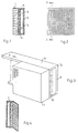
- Fig. 1
- Einen Schnitt längs der Linie I-I in Fig.;
- Fig. 2
- eine Vorderansicht eines Schallschutzelements nach der Erfindung;
- Fig. 3
- eine schaubildliche Darstellung des Schallschutzelements nach Fig. 2, wobei die Lochung des Akustikziegels aus Gründen der Vereinfachung unvollständig gezeichnet ist, und
- Fig. 4
- eine zur Fig. 1 analoge Darstellung eines erfindungsgemäßen Schallschutzelements, bei dem Akustikziegel mit Schräglochung zur Anwendung kommen.
- Fig. 1
- A section along the line II in Fig .;
- Fig. 2
- a front view of a soundproofing element according to the invention;
- Fig. 3
- 2, the perforation of the acoustic tile being drawn incompletely for reasons of simplification, and
- Fig. 4
- a representation analogous to FIG. 1 of a soundproofing element according to the invention, in which acoustic tiles with oblique perforations are used.
Ein erfindungsgemäßes Schallschutzelement besteht im wesentlichen aus mindestens zwei Gitterziegeln 1 mit Geradlochung oder Schräglochung (Fig. 4), einer die Rückseite der Gitterziegel 1 bedeckenden Schallschluck-Packung 2 in Form einer Platte aus einem Mineralfaservlies und einer Halterung 3 in Gestalt einer im Querschnitt U-förmigen Schale, welche die Schallschluck-Packung 2 von oben und unten - in Fig. 3 - umgreift und deren U-Schenkel 4 mit ihren Stirnrändern an der Rückseite der Gitterziegel 1 angeklebt sind. In dem gezeigten Ausführungsbeispiel hat jeder Gitterziegel 1 etwa quadratische Form und die Abmessungen der U-Schale 3 sind dieser angepaßt.A soundproofing element according to the invention essentially consists of at least two lattice tiles 1 with straight perforation or oblique perforation (FIG. 4), a sound absorption pack 2 covering the back of the lattice tiles 1 in the form of a plate made of a mineral fiber fleece and a holder 3 in the form of a U-shaped cross section. shaped Shell, which surrounds the sound absorbing pack 2 from above and below - in Fig. 3 - and whose
In dem dargestellten Ausführungsbeispiel nimmt die Schallschluck-Packung 2 nicht den ganzen Raum ein, der zwischen der Rückseite der Gitterziegel 1 und innerhalb der U-Schale 3 zur Verfügung steht. Vielmehr ist zwischen der Packung 2 und dem plattenförmigen Steg 5 der U-Schale 3 ein freier Raum 6 vorhanden, durch dessen Größe in gewissen Sinn die Schallschluckfähigkeit des Schallschutzelements beeinflußt werden kann. Es versteht sich jedoch, daß auch der Raum 6 mit einer weiteren Packung ausgefüllt sein kann.In the exemplary embodiment shown, the sound absorption pack 2 does not take up the entire space that is available between the rear of the lattice tiles 1 and within the U-shell 3. Rather, there is a free space 6 between the pack 2 and the plate-
Anstelle des in Fig. 3 gezeigten Schallschutzelementes, bei dem eine U-Schale 3 mit zwei Gitterziegeln 1 verbunden ist, können in der Richtung des Pfeils A (Fig. 3) mehrere Gitterziegel 1 nebeneinander angeordnet und durch eine ungeteilte U-Schale 3 zu einer Einheit vereinigt sein. Dabei entspricht die Länge der U-Schale 3 dann der Gesamtlänge der nebeneinander angeordneten Gitterziegel 1. Entsprechend kann die Schallschluck-Packung 2 durch einen Streifen aus einem Absorptionsmaterial gebildet sein, dessen Länge ebenfalls derjenigen der Gesamtanordnung entspricht. Derartige Schallschluck-Einheiten können vorgefertigt und auf der Baustelle, in vertikaler oder horizontaler Anordnung, erheblich rascher als die bekannten Schallschutzelemente mit rechteckigem Rahmen und im Verband verarbeitet werden. Insbesondere in dieser Ausführung ist es auch möglich, auf eine Stützmauer an der Rückseite des plattenförmigen U-Steges zu verzichten, weil die neben- oder übereinander angeordneten und mit ihren U-Schenkeln 4 miteinander verbundenen U-Schalen 3 eine ausreichende Eigenstabilität entwickeln.Instead of the soundproofing element shown in FIG. 3, in which a U-shell 3 is connected to two lattice tiles 1, in the direction of arrow A (FIG. 3), a plurality of lattice tiles 1 can be arranged next to one another and by an undivided U-shell 3 into one Unity. The length of the U-shell 3 then corresponds to the total length of the lattice tiles 1 arranged next to one another. Accordingly, the sound-absorbing pack 2 can be formed by a strip of an absorption material, the length of which likewise corresponds to that of the overall arrangement. Such sound absorption units can be prefabricated and processed on the construction site, in a vertical or horizontal arrangement, considerably faster than the known soundproofing elements with a rectangular frame and in association. In this embodiment in particular, it is also possible to dispense with a retaining wall on the rear side of the plate-shaped U-web, because the U-legs are arranged next to or above one another and with their
Es kann auch daran gedacht werden, die Länge der U-Schale grösser als die Gesamtlänge der darauf befestigten Akustikziegel zu wählen. Der überstehende Teil der U-Schale kann dabei zur Verankerung in angrenzendem Mauerwerk od.dgl. herangezogen werden.It can also be considered to choose the length of the U-shell to be greater than the total length of the acoustic tiles attached to it. The protruding part of the U-shell or the like can be anchored in adjacent masonry. be used.
Claims (7)
dadurch gekennzeichnet,
daß die die Löcher enthaltende Längswand durch zwei oder mehrere nebeneinander angeordnete Akustikziegel (1) mit Lochung gebildet ist, daß der restliche Teil des Keramikkörpers durch eine U-förmige Schale (3) gebildet ist, deren Länge der Summe der Einzellängen der Akustikziegel (1) wenigstens annähernd entspricht, und daß die Akustikziegel (1) mit den Stirnrändern der U-Schenkel (4) der U-förmigen Schale (3) verbunden sind.Soundproofing element in the form of a cuboid body having a cavity, of which a longitudinal wall (1) has a plurality of holes that pass through to the cavity and in the cavity of which a sound-absorbing packing (2) is arranged,
characterized,
that the longitudinal wall containing the holes is formed by two or more acoustic tiles (1) arranged next to one another with perforations, that the remaining part of the ceramic body is formed by a U-shaped shell (3), the length of which is the sum of the individual lengths of the acoustic tiles (1) corresponds at least approximately, and that the acoustic tiles (1) are connected to the end edges of the U-legs (4) of the U-shaped shell (3).
dadurch gekennzeichnet,
daß die schallschluckende Packung (2) ein Mineralfaservlies ist.Soundproofing element according to claim 1,
characterized,
that the sound absorbing packing (2) is a mineral fiber fleece.
dadurch gekennzeichnet,
daß die schallschluckende Packung (2) den Raum zwischen der Rückfläche der Akustikziegel (1) und dem plattenförmigen Steg (5) der U-förmigen Schale (3) nur teilweise ausfüllt.Soundproofing element according to claim 1 or 2,
characterized,
that the sound absorbing packing (2) only partially fills the space between the rear surface of the acoustic tiles (1) and the plate-shaped web (5) of the U-shaped shell (3).
dadurch gekennzeichnet,
daß die U-förmige Schale aus Keramikmaterial, insbesondere Ton, besteht.Soundproofing element according to one of claims 1 to 3,
characterized,
that the U-shaped shell made of ceramic material, in particular clay.
dadurch gekennzeichnet,
daß die U-förmige Schale mit den Akustikziegeln durch Klebung verbunden ist.Soundproofing element according to one of claims 1 to 4,
characterized,
that the U-shaped shell is connected to the acoustic tiles by gluing.
dadurch gekennzeichnet,
daß eine über zwei hinausgehende Mehrzahl von Akustikziegeln (1) nebeneinander oder übereinander angeordnet und mit einer einstückigen, durchgehenden U-förmigen Schale (3) verbunden ist.Soundproofing element according to one of claims 1 to 5,
characterized,
that a plurality of acoustic tiles (1) going beyond two are arranged side by side or one above the other and connected to a one-piece, continuous U-shaped shell (3).
dadurch gekennzeichnet,
daß die schallschluckende Packung (2) ein Streifen von der Länge der U-förmigen Schale ist.Soundproofing element according to claim 6,
characterized,
that the sound absorbing packing (2) is a strip the length of the U-shaped shell.
Applications Claiming Priority (2)
| Application Number | Priority Date | Filing Date | Title |
|---|---|---|---|
| DE9209991U | 1992-07-24 | ||
| DE9209991U DE9209991U1 (en) | 1992-07-24 | 1992-07-24 |
Publications (2)
| Publication Number | Publication Date |
|---|---|
| EP0580096A1 true EP0580096A1 (en) | 1994-01-26 |
| EP0580096B1 EP0580096B1 (en) | 1996-04-10 |
Family
ID=6882004
Family Applications (1)
| Application Number | Title | Priority Date | Filing Date |
|---|---|---|---|
| EP93111501A Expired - Lifetime EP0580096B1 (en) | 1992-07-24 | 1993-07-17 | Sound absorbing block |
Country Status (3)
| Country | Link |
|---|---|
| EP (1) | EP0580096B1 (en) |
| AT (1) | ATE136613T1 (en) |
| DE (2) | DE9209991U1 (en) |
Cited By (4)
| Publication number | Priority date | Publication date | Assignee | Title |
|---|---|---|---|---|
| EP0718347A1 (en) | 1994-12-24 | 1996-06-26 | Advanced Elastomer Systems, L.P. | Method to adhere thermoplastic elastomer blends to polyester substrates |
| WO2002022961A1 (en) | 2000-09-13 | 2002-03-21 | Wienerberger Bricks N.V. | Acoustic construction element for sound insulation in a broad range of frequencies |
| WO2003076736A1 (en) | 2002-03-14 | 2003-09-18 | Wienerberger Bricks N.V. | Acoustic construction element |
| EP2728082A1 (en) * | 2012-10-30 | 2014-05-07 | Denise Graul | Multi-layer brick and method for its production |
Families Citing this family (1)
| Publication number | Priority date | Publication date | Assignee | Title |
|---|---|---|---|---|
| CN103938560A (en) * | 2014-05-09 | 2014-07-23 | 佛山市中国科学院上海硅酸盐研究所陶瓷研发中心 | Ceramic sound absorption barrier |
Citations (4)
| Publication number | Priority date | Publication date | Assignee | Title |
|---|---|---|---|---|
| FR1576243A (en) * | 1967-08-17 | 1969-07-25 | ||
| US3846949A (en) * | 1972-01-26 | 1974-11-12 | Asahi Chemical Ind | Sound insulating block |
| DE2746849A1 (en) * | 1977-10-19 | 1979-04-26 | Volmer Betonwerk Gmbh & Co Kg | Construction block for noise screen wall - has E=shaped plan with sound absorbent sealing panels across open chambers |
| DE3012071A1 (en) * | 1980-03-28 | 1981-10-01 | Karl 5249 Hamm Rische | Sound insulating concrete type building slab - has readily replaceable non-combustible dense mineral wool panel to seal chamber |
Family Cites Families (4)
| Publication number | Priority date | Publication date | Assignee | Title |
|---|---|---|---|---|
| DE1928220U (en) * | 1965-06-23 | 1965-12-02 | Villeroy & Boch | SOUND-ABSORBING PANEL-SHAPED COMPONENT. |
| DE6601653U (en) * | 1966-10-08 | 1969-03-20 | W Gail'sche Tonwerke Kg | COMPONENTS FOR THE MANUFACTURE OF SOUND-ABSORBING WALLS |
| DE1963110A1 (en) * | 1969-12-07 | 1971-06-24 | Licentia Gmbh | Blue lateral magnet arrangement |
| DE8008573U1 (en) * | 1980-03-28 | 1980-07-17 | Rische, Karl, 5249 Hamm | SOUND-INSULATING AND SOUND-absorbing COMPONENT |
-
1992
- 1992-07-24 DE DE9209991U patent/DE9209991U1/de not_active Expired - Lifetime
-
1993
- 1993-07-17 AT AT93111501T patent/ATE136613T1/en not_active IP Right Cessation
- 1993-07-17 EP EP93111501A patent/EP0580096B1/en not_active Expired - Lifetime
- 1993-07-17 DE DE59302157T patent/DE59302157D1/en not_active Expired - Fee Related
Patent Citations (4)
| Publication number | Priority date | Publication date | Assignee | Title |
|---|---|---|---|---|
| FR1576243A (en) * | 1967-08-17 | 1969-07-25 | ||
| US3846949A (en) * | 1972-01-26 | 1974-11-12 | Asahi Chemical Ind | Sound insulating block |
| DE2746849A1 (en) * | 1977-10-19 | 1979-04-26 | Volmer Betonwerk Gmbh & Co Kg | Construction block for noise screen wall - has E=shaped plan with sound absorbent sealing panels across open chambers |
| DE3012071A1 (en) * | 1980-03-28 | 1981-10-01 | Karl 5249 Hamm Rische | Sound insulating concrete type building slab - has readily replaceable non-combustible dense mineral wool panel to seal chamber |
Cited By (4)
| Publication number | Priority date | Publication date | Assignee | Title |
|---|---|---|---|---|
| EP0718347A1 (en) | 1994-12-24 | 1996-06-26 | Advanced Elastomer Systems, L.P. | Method to adhere thermoplastic elastomer blends to polyester substrates |
| WO2002022961A1 (en) | 2000-09-13 | 2002-03-21 | Wienerberger Bricks N.V. | Acoustic construction element for sound insulation in a broad range of frequencies |
| WO2003076736A1 (en) | 2002-03-14 | 2003-09-18 | Wienerberger Bricks N.V. | Acoustic construction element |
| EP2728082A1 (en) * | 2012-10-30 | 2014-05-07 | Denise Graul | Multi-layer brick and method for its production |
Also Published As
| Publication number | Publication date |
|---|---|
| EP0580096B1 (en) | 1996-04-10 |
| ATE136613T1 (en) | 1996-04-15 |
| DE59302157D1 (en) | 1996-05-15 |
| DE9209991U1 (en) | 1992-09-24 |
Similar Documents
| Publication | Publication Date | Title |
|---|---|---|
| EP0580096B1 (en) | Sound absorbing block | |
| EP0051101A1 (en) | Cement slab, and process and device for producing the same | |
| EP0378217B1 (en) | Brick with vertical hollow passages and method of erecting a sound insulation wall | |
| DE102014108952A1 (en) | Slab edge formwork element | |
| EP1592852B1 (en) | Lost casing body | |
| EP1842984B1 (en) | Profiled edge element for concrete decks | |
| DE3631257C2 (en) | Component for soundproof walls | |
| DE102006022871B4 (en) | Method for producing a thermally insulating wall and thermally insulating wall | |
| DE3109937A1 (en) | Anti-noise wall element | |
| CH698206B1 (en) | Access basket for prefabricated double wall elements. | |
| DE10315441B4 (en) | Brick and method of laying the same | |
| AT399187B (en) | SOUND-INSULATING BUILDING WALL AND BRICK FOR USE IN SUCH | |
| EP1020584B1 (en) | Building block | |
| DE1911445A1 (en) | Prefabricated building element for concrete ceilings and concrete walls | |
| WO1997018374A1 (en) | Prefabricated window unit | |
| DE4407174A1 (en) | Brick roller shutter box | |
| DE19904394A1 (en) | Multi-function column for incorporation in external building walls | |
| DE102017108876A1 (en) | Shuttering element for the construction of noise barriers | |
| AT508153B1 (en) | NOISE ELEMENT | |
| DE2441164C2 (en) | Sound-absorbing wall element | |
| EP1767715A2 (en) | A glass brick wall | |
| AT397400B (en) | Connecting element for the layers of a multi-layer masonry structure | |
| DE3442183A1 (en) | Panel system having at least one panel which consists of cemented material | |
| DE19802270B4 (en) | Corner element for the cladding of walls or the like and method and device for producing such corner elements | |
| EP0561390A1 (en) | Buildingblock for electroinstallation |
Legal Events
| Date | Code | Title | Description |
|---|---|---|---|
| PUAI | Public reference made under article 153(3) epc to a published international application that has entered the european phase |
Free format text: ORIGINAL CODE: 0009012 |
|
| AK | Designated contracting states |
Kind code of ref document: A1 Designated state(s): AT BE CH DE FR GB LI LU NL |
|
| 17P | Request for examination filed |
Effective date: 19940617 |
|
| 17Q | First examination report despatched |
Effective date: 19950721 |
|
| GRAH | Despatch of communication of intention to grant a patent |
Free format text: ORIGINAL CODE: EPIDOS IGRA |
|
| GRAA | (expected) grant |
Free format text: ORIGINAL CODE: 0009210 |
|
| AK | Designated contracting states |
Kind code of ref document: B1 Designated state(s): AT BE CH DE FR GB LI LU NL |
|
| REF | Corresponds to: |
Ref document number: 136613 Country of ref document: AT Date of ref document: 19960415 Kind code of ref document: T |
|
| REG | Reference to a national code |
Ref country code: CH Ref legal event code: NV Representative=s name: PATENTANWALTSBUERO JEAN HUNZIKER |
|
| RAP2 | Party data changed (patent owner data changed or rights of a patent transferred) |
Owner name: ERLUS BAUSTOFFWERKE AG |
|
| PGFP | Annual fee paid to national office [announced via postgrant information from national office to epo] |
Ref country code: DE Payment date: 19960515 Year of fee payment: 4 |
|
| REF | Corresponds to: |
Ref document number: 59302157 Country of ref document: DE Date of ref document: 19960515 |
|
| PGFP | Annual fee paid to national office [announced via postgrant information from national office to epo] |
Ref country code: FR Payment date: 19960522 Year of fee payment: 4 |
|
| PGFP | Annual fee paid to national office [announced via postgrant information from national office to epo] |
Ref country code: LU Payment date: 19960601 Year of fee payment: 4 |
|
| PGFP | Annual fee paid to national office [announced via postgrant information from national office to epo] |
Ref country code: BE Payment date: 19960607 Year of fee payment: 4 |
|
| NLT2 | Nl: modifications (of names), taken from the european patent patent bulletin |
Owner name: ERLUS BAUSTOFFWERKE AG |
|
| GBT | Gb: translation of ep patent filed (gb section 77(6)(a)/1977) |
Effective date: 19960531 |
|
| PGFP | Annual fee paid to national office [announced via postgrant information from national office to epo] |
Ref country code: AT Payment date: 19960731 Year of fee payment: 4 |
|
| ET | Fr: translation filed | ||
| PGFP | Annual fee paid to national office [announced via postgrant information from national office to epo] |
Ref country code: CH Payment date: 19960802 Year of fee payment: 4 |
|
| PLBE | No opposition filed within time limit |
Free format text: ORIGINAL CODE: 0009261 |
|
| STAA | Information on the status of an ep patent application or granted ep patent |
Free format text: STATUS: NO OPPOSITION FILED WITHIN TIME LIMIT |
|
| 26N | No opposition filed | ||
| PG25 | Lapsed in a contracting state [announced via postgrant information from national office to epo] |
Ref country code: LU Free format text: LAPSE BECAUSE OF NON-PAYMENT OF DUE FEES Effective date: 19970717 Ref country code: GB Free format text: LAPSE BECAUSE OF NON-PAYMENT OF DUE FEES Effective date: 19970717 Ref country code: AT Free format text: LAPSE BECAUSE OF NON-PAYMENT OF DUE FEES Effective date: 19970717 |
|
| PG25 | Lapsed in a contracting state [announced via postgrant information from national office to epo] |
Ref country code: LI Free format text: LAPSE BECAUSE OF NON-PAYMENT OF DUE FEES Effective date: 19970731 Ref country code: CH Free format text: LAPSE BECAUSE OF NON-PAYMENT OF DUE FEES Effective date: 19970731 Ref country code: BE Free format text: LAPSE BECAUSE OF NON-PAYMENT OF DUE FEES Effective date: 19970731 |
|
| BERE | Be: lapsed |
Owner name: ERLUS BAUSTOFFWERKE A.G. Effective date: 19970731 |
|
| PG25 | Lapsed in a contracting state [announced via postgrant information from national office to epo] |
Ref country code: NL Free format text: LAPSE BECAUSE OF NON-PAYMENT OF DUE FEES Effective date: 19980201 |
|
| GBPC | Gb: european patent ceased through non-payment of renewal fee |
Effective date: 19970717 |
|
| REG | Reference to a national code |
Ref country code: CH Ref legal event code: PL |
|
| PG25 | Lapsed in a contracting state [announced via postgrant information from national office to epo] |
Ref country code: FR Free format text: LAPSE BECAUSE OF NON-PAYMENT OF DUE FEES Effective date: 19980331 |
|
| NLV4 | Nl: lapsed or anulled due to non-payment of the annual fee |
Effective date: 19980201 |
|
| PG25 | Lapsed in a contracting state [announced via postgrant information from national office to epo] |
Ref country code: DE Free format text: LAPSE BECAUSE OF NON-PAYMENT OF DUE FEES Effective date: 19980401 |
|
| REG | Reference to a national code |
Ref country code: FR Ref legal event code: ST |