EP0579902B1 - Automatischer Variator für Überlappung und Durchgang eines Drehschiebers - Google Patents
Automatischer Variator für Überlappung und Durchgang eines Drehschiebers Download PDFInfo
- Publication number
- EP0579902B1 EP0579902B1 EP93105631A EP93105631A EP0579902B1 EP 0579902 B1 EP0579902 B1 EP 0579902B1 EP 93105631 A EP93105631 A EP 93105631A EP 93105631 A EP93105631 A EP 93105631A EP 0579902 B1 EP0579902 B1 EP 0579902B1
- Authority
- EP
- European Patent Office
- Prior art keywords
- shaft
- valve
- ice
- spindle
- assembly according
- Prior art date
- Legal status (The legal status is an assumption and is not a legal conclusion. Google has not performed a legal analysis and makes no representation as to the accuracy of the status listed.)
- Expired - Lifetime
Links
Images


Classifications
-
- F—MECHANICAL ENGINEERING; LIGHTING; HEATING; WEAPONS; BLASTING
- F01—MACHINES OR ENGINES IN GENERAL; ENGINE PLANTS IN GENERAL; STEAM ENGINES
- F01L—CYCLICALLY OPERATING VALVES FOR MACHINES OR ENGINES
- F01L7/00—Rotary or oscillatory slide valve-gear or valve arrangements
- F01L7/02—Rotary or oscillatory slide valve-gear or valve arrangements with cylindrical, sleeve, or part-annularly shaped valves
- F01L7/026—Rotary or oscillatory slide valve-gear or valve arrangements with cylindrical, sleeve, or part-annularly shaped valves with two or more rotary valves, their rotational axes being parallel, e.g. 4-stroke
-
- F—MECHANICAL ENGINEERING; LIGHTING; HEATING; WEAPONS; BLASTING
- F01—MACHINES OR ENGINES IN GENERAL; ENGINE PLANTS IN GENERAL; STEAM ENGINES
- F01L—CYCLICALLY OPERATING VALVES FOR MACHINES OR ENGINES
- F01L1/00—Valve-gear or valve arrangements, e.g. lift-valve gear
- F01L1/34—Valve-gear or valve arrangements, e.g. lift-valve gear characterised by the provision of means for changing the timing of the valves without changing the duration of opening and without affecting the magnitude of the valve lift
-
- F—MECHANICAL ENGINEERING; LIGHTING; HEATING; WEAPONS; BLASTING
- F01—MACHINES OR ENGINES IN GENERAL; ENGINE PLANTS IN GENERAL; STEAM ENGINES
- F01L—CYCLICALLY OPERATING VALVES FOR MACHINES OR ENGINES
- F01L13/00—Modifications of valve-gear to facilitate reversing, braking, starting, changing compression ratio, or other specific operations
- F01L13/0015—Modifications of valve-gear to facilitate reversing, braking, starting, changing compression ratio, or other specific operations for optimising engine performances by modifying valve lift according to various working parameters, e.g. rotational speed, load, torque
-
- F—MECHANICAL ENGINEERING; LIGHTING; HEATING; WEAPONS; BLASTING
- F02—COMBUSTION ENGINES; HOT-GAS OR COMBUSTION-PRODUCT ENGINE PLANTS
- F02B—INTERNAL-COMBUSTION PISTON ENGINES; COMBUSTION ENGINES IN GENERAL
- F02B1/00—Engines characterised by fuel-air mixture compression
- F02B1/02—Engines characterised by fuel-air mixture compression with positive ignition
- F02B1/04—Engines characterised by fuel-air mixture compression with positive ignition with fuel-air mixture admission into cylinder
-
- F—MECHANICAL ENGINEERING; LIGHTING; HEATING; WEAPONS; BLASTING
- F02—COMBUSTION ENGINES; HOT-GAS OR COMBUSTION-PRODUCT ENGINE PLANTS
- F02B—INTERNAL-COMBUSTION PISTON ENGINES; COMBUSTION ENGINES IN GENERAL
- F02B75/00—Other engines
- F02B75/02—Engines characterised by their cycles, e.g. six-stroke
- F02B2075/022—Engines characterised by their cycles, e.g. six-stroke having less than six strokes per cycle
- F02B2075/027—Engines characterised by their cycles, e.g. six-stroke having less than six strokes per cycle four
-
- F—MECHANICAL ENGINEERING; LIGHTING; HEATING; WEAPONS; BLASTING
- F02—COMBUSTION ENGINES; HOT-GAS OR COMBUSTION-PRODUCT ENGINE PLANTS
- F02B—INTERNAL-COMBUSTION PISTON ENGINES; COMBUSTION ENGINES IN GENERAL
- F02B2275/00—Other engines, components or details, not provided for in other groups of this subclass
- F02B2275/18—DOHC [Double overhead camshaft]
-
- F—MECHANICAL ENGINEERING; LIGHTING; HEATING; WEAPONS; BLASTING
- F02—COMBUSTION ENGINES; HOT-GAS OR COMBUSTION-PRODUCT ENGINE PLANTS
- F02F—CYLINDERS, PISTONS OR CASINGS, FOR COMBUSTION ENGINES; ARRANGEMENTS OF SEALINGS IN COMBUSTION ENGINES
- F02F7/00—Casings, e.g. crankcases
- F02F7/006—Camshaft or pushrod housings
Definitions
- the present invention relates an automatic variator assembly for use in internal combustion engines (i.e., cars, trucks, etc.) or any machine which uses double effect distribution sequential valve shaft as disclosed in co-pending application entitled DOUBLE EFFECT DISTRIBUTION SEQUENTIAL VALVE SHAFT, filed concurrently herewith, and incorporated herein by reference.
- the present invention deals with an automatic valve overlap and valve section variator, for use in internal combustion engines.
- valves in internal combustion engines is related to the precise timing of the opening of the intake valve in relation to the precise timing of the opening of the intake valve in relation to the opening of the exhaust valve at given points in the location of the piston, be it at the bottom or at the top of the cylinder.
- the exhaust valve begins to open at the end of the third stroke and remains open during the entire fourth stroke, at which point the intake valve begins to open before the fist stroke. The instant during which both valves are open is designated "overlap" in this description.
- the object of the invention is to provide an automatic variator assembly for an internal combustion engine using the double effect distribution sequential valve shaft system ("SVS") and allowing an axial displacement and a rotation of the shaft through a simplified actuating mechanism. This object is achieved with an automatic variator assembly according to the independent claim 1.
- this invention modifies the opening section, as more fully described below, to enlarge or reduce the space through which the gases will flow in the distribution system.
- the enlargement of valve area occurs only by depressing the valve deeper, which has proven to cause serious difficulties in the behavior of cams and springs.
- the device of the present invention unlike the prior art, allows the valve overlap and the opening section to be varied in a double effect distribution sequential valve shaft.
- the present invention includes an automatic valve overlap and valve section variator for use in internal combustion engines and machines which use valve-type distribution systems with cams or distribution valve shafts.
- the invention includes an automatic mechanism controlled by a microprocessor which is activated by a signal received from a tachometer, or gas analyzer, or both.
- the automatic mechanism activates a motor reducer with a step motor or a servo motor which turns a number of predetermined turns or steps.
- the motor reducer by means of a hollow and internally threaded crown of the reducer, causes an end of a spindle to advance against bearings which push the SVS shaft against a dragging pulley by means of a multiple entrance grooved screw etched in at one end of the SVS shaft and an axle box inside the pulley in such a way that a differential and controlled turn is produced in the SVS shaft with respect to a dragging pulley.
- a differential and controlled turn is produced in the SVS shaft with respect to a dragging pulley.
- the rotation which changes the angular position of the SVS shaft is concurrent with a longitudinal displacement of the shaft, both resulting from the action of the spindle against the end of the shaft.
- Such displacement will change the relative positions of the perforations or openings in the shaft and in the jacket in which the shaft is inserted, whereby their common area will be less than if they coincided entirely.
- the variation in valve area may occur in either sense, i.e. the common valve area may be increased or decreased.
- the step motor or servo motor can be actuated in forward or reverse with the effect of changing simultaneously the overlap and the valve section conditions of the distribution system. Such effect is obtained by the coordinated variation of both SVS shafts, one for intake and one for exhaust.
- Fig. 1A illustrates the distribution system with which the present invention is used.
- Fig. 1B illustrates a detailed view of a portion of the distribution system in Fig. 1A.
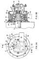
- Fig. 2A illustrates a top elevation view of the variator of the present invention.
- Fig. 2B illustrates a cross-sectional side elevation view of the variator of Fig. 1A taken along the line A-A.
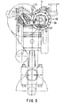
- Fig. 3 illustrates the mounting of the system of the present invention on the distribution system illustrated in Fig. 1A in a frontal view.
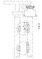
- Fig. 4 illustrates the mounting of the system of the present invention in a lateral view.
- Fig. 5 illustrates the mounting of the system of the present invention in a superior view.
- the present invention is described below by illustrating its function as it relates to a system in an engine with a double effect distribution sequential valve shaft system ("SVS"), as shown in Figs. 1A and 1B, located in the cylinder head of the engine and driven by toothed pulleys and belts, gears, or chains with one shaft for intake and another for exhaust.
- SVS sequential valve shaft system
- the SVS shafts include two longitudinal shafts (a) and (b) on the cylinder head 5 aligned with the engine axis, comprising a jacket 1 and a shaft formed with holes, i.e., a holed shaft.
- the engine includes motor block 7, piston 8, cylinder head 5, connecting rod 12, a distribution toothed belt 9, distribution and reduction toothed pulley 11, tension pulley 13, and motion distribution toothed pulley 14.
- a housing for two jackets is provided in the cylinder head cover 5, with outer water chambers.
- the jacket 1 with perforations or openings 20 from side to side in the vertical plane of the jacket, is inserted into the housing under pressure and with a sealer. Each opening 20 coincides with a combustion chamber of each cylinder of the engine.
- a double effect distribution sequential valve shaft 2 is mounted inside the jacket 1 with a very accurate tolerance.
- the shaft also has perforations or openings 22 extending from side to side in the vertical plane. Each opening 22 is separated from the other by the same distance between cylinders and is placed at a predetermined angle in the vertical plane, depending on the sequence of intake or exhaust on the type of engine.
- the openings 22 of the shaft are side to side in the vertical plane, at every complete turn, one of the openings 22 communicates twice every turn through an opening 20 in the jacket 1 with a hole 24 in the head of one combustion chamber of a given cylinder 3, for which reason it is named "double effect.”
- one complete turn of the crankshaft need only result in 1/4 of a turn of the double effect distribution sequential valve shaft 2.
- the rotation of the valve shaft is transmitted from a pulley 14 on the crankshaft 25 by means of pulleys and toothed belts 11 and 9, with a corresponding difference of diameters to reduce the number of turns to 4:1.
- the exhaust or intake exit is shown at 4 in Fig. 1B.
- the present invention is described below according to details of Figs. 2A, 2B, 3, 4 and 5.
- the present invention is an automatic mechanism commanded by a servo-motor or a step motor whose turns are controlled by an electronic circuit.
- the electronic circuit receives instructions from a tachometer, gas analyzer, or both, which indicates the variations of valve overlap for a certain rate of revolutions per minute.
- a motor reducer 42 forms a single body with a worm gear and an endless worm or screw.
- a holder plate of the motor reducer 42 is coupled to a motor body 37 by means of screws 43.
- the shaft 2 has at its end a grooved trapezoidal screw channel 41 with multiple entrances which is screwed into a hollow and grooved axle box 34 which is engaged with a toothed pulley 49 by means of a pin.
- the axle box 34 is restrained from moving longitudinally by means of a seeger ring 35.
- a plate 27 supports the whole unit and is fixed to the block by means of screws 38.
- the plate 27 supports a ball bearing 30 which is fixed in its position with the seeger ring 15 and rubber locks 28 and 29.
- the toothed pulley 49 and the axle box 34 are fixed to the ball bearing 30 by means of a ring 31 and screws 33 such that longitudinal movement of the pulley is restrained and the pulley is only able to turn.
- the SVS shaft 2 has etched on its end a housing for axial ball bearings 40.
- a cap with screws 45 and a rubber lock 46 close the housing.
- a pushing spindle 44 is retained between both axial ball bearings 30.
- the pushing spindle 44 in turn is screwed into the hollow bore of the worm gear of the motor reducer 42.
- the spindle 44 has a longitudinal square section groove in which a pin 39 enters, in such a way as to prevent the spindle 44 from turning while allowing longitudinal movement.
- the pin 39 is fixed to the body 37 by means of a screw 32.
- the motor reducer 42 When the motor reducer 42 receives a signal, it moves a determined amount of turns or steps. The rotation of the motor reducer 42 is transmitted to the spindle 44 which pushes the shaft 2 along the grooves 41. The shaft 2 thereby turns over itself according to the produced advance. When the motor reducer 42 completes its rotation, the whole unit has produced a differential rotation resulting in advance of the shaft 2 and amplification or reduction of the common area between the shaft perforations or openings 22 and those of its jackets. The rotation of the shaft 2 also changes the valve overlap with respect to the other twin shaft, and with reference to the position of the piston at the top or bottom of its motion.
- the opening for the intake or the exhaust of the mixture or the gases through the cylinder head covers has been indicated at 24 and the opening on the shaft has been indicated at 22.
- the opening 22 has been advanced relative to the opening 24.
- the projections of the openings in Fig. 5 have been indicated without taking into account the turning of the shaft 2.
- the effective opening is determined by the common area between the opening 24 and the opening 22. The maximum possible opening will be area of opening X.
- valve overlap and the valve section is carried out while the engine is running and at any range of revolutions per minute.
- a removable cap 47 allows for the change of a distribution belt 48_ whose possible positions are indicated at 48.
- Fig. 3 shows the mounting of the system in a frontal view, while the mounting of the system laterally is shown in Fig. 4.
- Fig. 5 shows the top view of the assembly shown in Fig. 4.
- the device of the present invention may be moved directly by a separate reducer, by a single body motor reducer of the type having a worm gear or crown and endless worm or screw or by other known type.
- the screw threads may be of any known type.
- the threaded axle box 34 and shaft 2 may have one or multiple entrances of any pitch. In other words, if the pitch were infinite there should be a groove of parallel teeth so that when the spindle 44 pushes the shaft 2 there is only longitudinal movement, without rotation, thereby varying only the valve section in the system.
- the axle box 34 may be a separate element or form one single body with the pulley.
- the pulley and the spindle 44 may be mounted on bushings or bearings of any type.
- Lubrication may be in an independent circuit or, depending on the engine, or may be provided by auto-lubricating mechanisms.
- the invention may be moved indirectly by the main engine or by an independent, electric, hydraulic or pneumatic or any known type of motor.
- the spindle 44 may be moved directly or indirectly by hydraulic or pneumatic systems.
- the invention may be commanded by an electronic or electric circuit, with input of one or more variables or combinations thereof. Further, the invention may be set up with a sensor in such a way that when the main engine stops, the valve overlap position and the valve section return to the position at the point of start up.
- the present invention advantageously allows the optimum performance of intake or exhaust of gases at any rate of revolutions per minute, to be obtained automatically.
- the present invention allows: (a) greater efficiency in expulsion of exhaust gases; (b) greater efficiency of mixture intake; (c) better combustion in the chambers; (d) greater power generation at a given rate of revolutions per minute; and (e) less combustion residuals due to a better burning of the fuel mixture.
Landscapes
- Engineering & Computer Science (AREA)
- Mechanical Engineering (AREA)
- General Engineering & Computer Science (AREA)
- Valve Device For Special Equipments (AREA)
- Valve-Gear Or Valve Arrangements (AREA)
- Control Of Throttle Valves Provided In The Intake System Or In The Exhaust System (AREA)
Claims (7)
- Automatische Variator-Anordnung für eine Brennkraftmaschine oder BKM umfassend:- eine zylindrische Ventilwelle mit einer in einer senkrechten Ebene von einer Seite zur anderen durchgehenden Öffnung, die von einer Kurbelwelle BKM angetrieben wird,- einer automatisch arbeitenden Einrichtung, die von einem Mikroprozessor gesteuert wird, der von einem Signal eines Drehzahlgebers oder eines Gasanalysators oder von beiden beaufschlagt wird, und- Mittel zur Bewegung der Ventilwelle,dadurch gekennzeichnet, daß- der Variator zur Veränderung des Ventildurchgangs und der Ventilüberlappung bei einem doppelt wirkenden Ventilwellen-Verteilungsfolgesystem der BKM dient, das umfaßt:= ein Verteilungssystem, bestehend aus zwei drehenden Ventilwellen (2), die in zylindrischen Hülsen (1) innerhalb des Zylinderkopfes der BKM angeordnet sind,= wobei jede Welle (2) unter verschiedenen Winkeln bezogen auf eine senkrechte Ebene verlaufend mehr als eine von einer Seite zur anderen durchgehende Öffnung (22) aufweist und jede Hülse (1) in gleicher Weise mehr als ein Paar Öffnungen (20) unter demselben Winkel bezogen auf eine senkrechte Ebene aufweist,= wobei jeweils ein offener Kanal gebildet wird, wenn die Öffnungen (22, 20) bei jeder halben Umdrehung der Welle (2) miteinander fluchten, um einen Durchgang für den Einlaß des Brennstoffgemisches oder für den Auslaß der Verbrennungsgase zwischen den zugehörigen Zylinderkopföffnungen (24) und der Einlaß- und Auslaßleitung der BKM herzustellen,- die Mittel zur Bewegung der Ventilwelle (2) sind:= eine Druckstange (44),= ein Getriebemotor (42) oder Schrittmotor oder Hilfsmotor, der von besagter automatischer Einrichtung beaufschlagt wird und sich um eine vorgegebene Anzahl von Umdrehungen oder Schritten dreht, wodurch bewirkt wird, daß ein Ende der Druckstange (44) sich bewegt und die Ventilwelle (2) vorwärtsschiebt oder zurückzieht,= eine Achsialbuchse (34) mit Innengewinde und= ein mehrgängiges Schraubgewinde (41), das in ein Ende der Ventilwelle (2) eingearbeitet ist und sich in der Achsialbuchse (34) derartig dreht, daß eine kleine und geregelte Verdrehung der Welle (2) hervorgerufen wird, wenn die Druckstange (44) die Welle (2) verschiebt und dabei eine aus einer Drehung und axialen Verschiebung zusammengesetzte Bewegung der Welle (2) hervorruft,- wobei diese Verschiebung innerhalb der die Welle (2) umgebenden Hülse (1) bei einer BKM den Ventilöffnungsquerschnitt und die Ventilüberlappung verändert.
- Variator-Anordnung nach Anspruch 1, jedoch mit der Maßgabe, daß die Steigung des Gewindes unendlich ist, so daß die Ausnehmungen parallel verlaufen und nur eine Längsverschiebung stattfindet und nur der Ventilöffnungsquerschnitt verändert wird, wenn die Druckstange (44) die Welle (2) vorwärts bewegt.
- Variator-Anordnung nach Anspruch 1 oder 2, dadurch gekennzeichnet, daß der Getriebemotor (42) eine Getriebeschnecke aufweist und daß die Druckstange (44) in die Gewindeschnecke eingeschraubt ist.
- Variator-Anordnung nach einem der Ansprüche 1 bis 3, dadurch gekennzeichnet, daß die Achsialbuchse (34) mit Innengewinde relativ zur Druckstange (44) unbeweglich angeordnet ist und daß das Schraubgewinde (41) in die Achsialbuchse (34) mit Innengewinde eingeschraubt ist.
- Variator-Anordnung nach einem der Ansprüche 1 bis 4, dadurch gekennzeichnet, daß der Getriebemotor (2) in Abhängigkeit von einem Mikroprozessor arbeitet, der die Veränderungen der Ventilüberlappung für einen vorgegebenen Bereich von Umdrehungen pro Minute angibt.
- Variator-Anordnung nach Anspruch 5, dadurch gekennzeichnet, daß der Mikroprozessor in Abhängigkeit von einem Drehzahlgeber arbeitet, der die Veränderungen der Ventilüberlappung für einen bestimmten Bereich von Umdrehungen pro Minute angibt.
- Variator-Anordnung nach einem der Ansprüche 1 bis 6, dadurch gekennzeichnet, daß sie bei einer BKM mit nur einem Zylinder verwendet wird, wobei die beiden sich drehenden, im Zylinderkopf der BKM angeordneten Ventilwellen (2) eine Öffnung (22) aufweisen, die sich quer durch sie hindurch erstrecken, und wobei die Hülsen (1) in der Wandung der Hülsen (1) ein Paar diametral gegenüberliegende Öffnungen (20) aufweisen.
Applications Claiming Priority (4)
| Application Number | Priority Date | Filing Date | Title |
|---|---|---|---|
| AR322785 | 1992-07-20 | ||
| AR32278592 | 1992-07-20 | ||
| AR32286292 | 1992-07-31 | ||
| AR322862 | 1992-07-31 |
Publications (2)
| Publication Number | Publication Date |
|---|---|
| EP0579902A1 EP0579902A1 (de) | 1994-01-26 |
| EP0579902B1 true EP0579902B1 (de) | 1997-08-13 |
Family
ID=25591012
Family Applications (1)
| Application Number | Title | Priority Date | Filing Date |
|---|---|---|---|
| EP93105631A Expired - Lifetime EP0579902B1 (de) | 1992-07-20 | 1993-04-06 | Automatischer Variator für Überlappung und Durchgang eines Drehschiebers |
Country Status (6)
| Country | Link |
|---|---|
| US (1) | US5309876A (de) |
| EP (1) | EP0579902B1 (de) |
| JP (1) | JP2575274B2 (de) |
| AT (1) | ATE156893T1 (de) |
| DE (1) | DE69313048T2 (de) |
| ES (1) | ES2106914T3 (de) |
Cited By (1)
| Publication number | Priority date | Publication date | Assignee | Title |
|---|---|---|---|---|
| WO2002097244A1 (en) * | 2001-05-30 | 2002-12-05 | Bishop Innovation Limited | Valve timing mechanism for a rotary valve internal combustion engine |
Families Citing this family (19)
| Publication number | Priority date | Publication date | Assignee | Title |
|---|---|---|---|---|
| US5392743A (en) * | 1994-03-28 | 1995-02-28 | Dokonal; Jindrich | Variable duration rotary valve |
| US5572967A (en) * | 1994-08-26 | 1996-11-12 | Three Star Enterprises, Inc. | Variable roller valve system for internal combustion engine |
| US5582140A (en) * | 1995-05-04 | 1996-12-10 | Strieber; Louis C. | Rotatable timed mechanism for feeding vaporous fluid to a combustion cylinder |
| US6125819A (en) * | 1995-08-08 | 2000-10-03 | Strieber; Louis Charles | Rotating piston engine with variable effective compression stroke |
| US5841669A (en) * | 1996-01-26 | 1998-11-24 | Howmet Research Corporation | Solidification control including pattern recognition |
| US5579730A (en) * | 1996-02-09 | 1996-12-03 | Trotter; Richard C. | Rotary valve head assembly and related drive system for internal combustion engines |
| US5706775A (en) * | 1996-04-12 | 1998-01-13 | New Avenue Development Corp. | Rotary valve apparatus for internal combustion engines and methods of operating same |
| US5967108A (en) | 1996-09-11 | 1999-10-19 | Kutlucinar; Iskender | Rotary valve system |
| US6029617A (en) * | 1998-05-12 | 2000-02-29 | Lambert; Steven | Modular rotary discoid valve assembly for engines and other applications |
| US6443110B2 (en) | 1999-12-10 | 2002-09-03 | Jamal Umar Qattan | Rotary valve head system for multi-cylinder internal combustion engines |
| US6691664B2 (en) * | 2001-04-12 | 2004-02-17 | Joseph Samuel Pisano | Direct port rotary valve mechanism with variable timing for internal combustion engines |
| US6595177B1 (en) | 2002-02-27 | 2003-07-22 | Kramer Jewelers, Inc. #2 | Rotary sleeve port for an internal combustion engine |
| RU2243387C2 (ru) * | 2002-03-04 | 2004-12-27 | Чоповский Борис Петрович | Двигатель внутреннего сгорания (варианты) |
| US20040256281A1 (en) * | 2003-03-19 | 2004-12-23 | Keith Cangiarella | Novelty message kit |
| GR1006591B (el) * | 2008-06-02 | 2009-11-11 | Βαση στηριξης φωτοβολταϊκων συλλεκτων περιστρεφομενη περι οριζοντιου και κατακορυφου αξονα ταυτοχρονα | |
| US8714119B2 (en) * | 2008-06-05 | 2014-05-06 | Stuart B. Pett, Jr. | Parallel cycle internal combustion engine with double headed, double sided piston arrangement |
| US8499727B1 (en) | 2008-06-05 | 2013-08-06 | Stuart B. Pett, Jr. | Parallel cycle internal combustion engine |
| RU2008132472A (ru) * | 2008-08-07 | 2010-02-20 | Андрей Владимирович Фотеев (RU) | Бескулачковый газораспределительный механизм на основе двух пар цилиндрических золотников с возможностью регулировки фаз газораспределения |
| US10711667B2 (en) * | 2018-01-31 | 2020-07-14 | Jonathan TAVERNIER | Internal combustion engine with tubular valves and braking system |
Citations (1)
| Publication number | Priority date | Publication date | Assignee | Title |
|---|---|---|---|---|
| US1513911A (en) * | 1922-01-28 | 1924-11-04 | Clyde W Keller | Internal-combustion engine |
Family Cites Families (18)
| Publication number | Priority date | Publication date | Assignee | Title |
|---|---|---|---|---|
| US1863875A (en) * | 1929-08-31 | 1932-06-21 | Rabezzana Hector | Internal combustion engine |
| US2839036A (en) * | 1956-05-07 | 1958-06-17 | Kiekhaefer Corp | Rotary valve timing mechanism |
| US3993036A (en) * | 1974-08-27 | 1976-11-23 | Tischler Wald E | Internal combustion engine |
| US4163438A (en) * | 1975-11-26 | 1979-08-07 | Dana Corporation | Rotary valve timing apparatus |
| US4302985A (en) * | 1979-12-21 | 1981-12-01 | Ford Motor Company | Phase controlling system for two rotatable shafts |
| DE3146613A1 (de) * | 1981-11-25 | 1983-06-01 | Ford-Werke AG, 5000 Köln | Vorrichtung zum belastungs- und drehzahlabhaengigen veraendern der ventilsteuerzeiten von brennkraftmaschinen |
| JPS5987214A (ja) * | 1982-11-12 | 1984-05-19 | Toyota Motor Corp | 内燃機関のバルブタイミング制御装置 |
| JPS60125712A (ja) * | 1983-12-12 | 1985-07-05 | Yuki Tsukamoto | エンジンの吸排気バルブ装置 |
| JPS61237825A (ja) * | 1985-04-12 | 1986-10-23 | Mazda Motor Corp | ロ−タリバルブ付エンジン |
| US4864984A (en) * | 1986-09-02 | 1989-09-12 | Blish Nelson A | Rotary valve internal combustion engine |
| US4738223A (en) * | 1986-11-13 | 1988-04-19 | Andreasen Howard L | Horse training apparatus |
| DE3830382C1 (de) * | 1988-09-07 | 1990-01-18 | Daimler-Benz Aktiengesellschaft, 7000 Stuttgart, De | |
| JPH02169818A (ja) * | 1988-12-21 | 1990-06-29 | Fuji Heavy Ind Ltd | 2サイクルエンジン |
| JPH086568B2 (ja) * | 1989-04-13 | 1996-01-24 | 日産自動車株式会社 | エンジンの弁作動制御装置 |
| US4976229A (en) * | 1990-02-12 | 1990-12-11 | Siemens Automotive L.P. | Engine camshaft phasing |
| US4976227A (en) * | 1990-04-16 | 1990-12-11 | Draper David J | Internal combustion engine intake and exhaust valve control apparatus |
| JPH04241709A (ja) * | 1991-01-11 | 1992-08-28 | Toyota Motor Corp | 軸間位相変換装置 |
| US5105784A (en) * | 1991-04-08 | 1992-04-21 | General Motors Corporation | Rotary valve and system for duration and phase control |
-
1993
- 1993-01-21 US US08/006,944 patent/US5309876A/en not_active Expired - Fee Related
- 1993-04-06 DE DE69313048T patent/DE69313048T2/de not_active Expired - Fee Related
- 1993-04-06 EP EP93105631A patent/EP0579902B1/de not_active Expired - Lifetime
- 1993-04-06 AT AT93105631T patent/ATE156893T1/de active
- 1993-04-06 ES ES93105631T patent/ES2106914T3/es not_active Expired - Lifetime
- 1993-04-15 JP JP5088675A patent/JP2575274B2/ja not_active Expired - Lifetime
Patent Citations (1)
| Publication number | Priority date | Publication date | Assignee | Title |
|---|---|---|---|---|
| US1513911A (en) * | 1922-01-28 | 1924-11-04 | Clyde W Keller | Internal-combustion engine |
Cited By (1)
| Publication number | Priority date | Publication date | Assignee | Title |
|---|---|---|---|---|
| WO2002097244A1 (en) * | 2001-05-30 | 2002-12-05 | Bishop Innovation Limited | Valve timing mechanism for a rotary valve internal combustion engine |
Also Published As
| Publication number | Publication date |
|---|---|
| JPH0681619A (ja) | 1994-03-22 |
| DE69313048T2 (de) | 1998-01-15 |
| DE69313048D1 (de) | 1997-09-18 |
| EP0579902A1 (de) | 1994-01-26 |
| US5309876A (en) | 1994-05-10 |
| JP2575274B2 (ja) | 1997-01-22 |
| ATE156893T1 (de) | 1997-08-15 |
| ES2106914T3 (es) | 1997-11-16 |
Similar Documents
| Publication | Publication Date | Title |
|---|---|---|
| EP0579902B1 (de) | Automatischer Variator für Überlappung und Durchgang eines Drehschiebers | |
| EP0636768B1 (de) | Automatische Verstellvorrichtung zur Verstellung der Ventilsteuerzeiten | |
| CA1240576A (en) | Phasing device for machinery applications | |
| US5860328A (en) | Shaft phase control mechanism with an axially shiftable splined member | |
| US5509384A (en) | Variable valve timing gear | |
| EP0741235B1 (de) | Doppelausgangs-Nockenwellenphasenregler | |
| DE3619956C2 (de) | ||
| DE19903594A1 (de) | Verstellbare Ventilsteuervorrichtung | |
| KR19990037055A (ko) | 가역식 디젤 연소 기관의 밸브 제어용 장치 및 그 방법 | |
| AU761000B2 (en) | Overhead camshaft V-2 engine | |
| EP0367192A1 (de) | Ventilantriebsvorrichtung für Brennkraftmaschine | |
| DE19852252A1 (de) | Hydraulische Einrichtung zur Einstellung des Öffnungs- und Schließzeitpunkts eines Motorventils | |
| DE69409619T2 (de) | Sequentieller Drehschieber mit doppeltwirkender Steuerung | |
| US5125372A (en) | Hydraulically operated engine valve system | |
| EP0791727B1 (de) | Nockenwelle einer Brennkraftmaschine, die von einer variablen Ventilsteuervorrichtung angetrieben wird | |
| DE69711281T2 (de) | Variable Ventilsteuervorrichtung für Verbrennungsmotor | |
| KR0130587B1 (ko) | 내연기관의 가변압축비 장치 | |
| WO1991002897A1 (de) | Kraftstoffeinspritzpumpe für brennkraftmaschinen | |
| JPH07189624A (ja) | バルブのオーバラップ又はタイミング、及びバルブ断面の自動変更装置 | |
| DE19731974A1 (de) | Hubkolbenbrennkraftmaschine | |
| US5133305A (en) | Internal combustion engine having rotary engine body | |
| KR0180877B1 (ko) | 차량 엔진의 로커암타입 흡기밸브 흡기량 가변장치 | |
| SU1259049A1 (ru) | Двигатель внутреннего сгорани | |
| KR970000750B1 (ko) | 자동차용 흡,배기밸브 개폐 가변장치 | |
| EP0394763A1 (de) | Verbrennungsmotor |
Legal Events
| Date | Code | Title | Description |
|---|---|---|---|
| PUAI | Public reference made under article 153(3) epc to a published international application that has entered the european phase |
Free format text: ORIGINAL CODE: 0009012 |
|
| AK | Designated contracting states |
Kind code of ref document: A1 Designated state(s): AT DE ES FR GB IT SE |
|
| 17P | Request for examination filed |
Effective date: 19940712 |
|
| 17Q | First examination report despatched |
Effective date: 19950327 |
|
| GRAG | Despatch of communication of intention to grant |
Free format text: ORIGINAL CODE: EPIDOS AGRA |
|
| GRAH | Despatch of communication of intention to grant a patent |
Free format text: ORIGINAL CODE: EPIDOS IGRA |
|
| GRAH | Despatch of communication of intention to grant a patent |
Free format text: ORIGINAL CODE: EPIDOS IGRA |
|
| GRAA | (expected) grant |
Free format text: ORIGINAL CODE: 0009210 |
|
| AK | Designated contracting states |
Kind code of ref document: B1 Designated state(s): AT DE ES FR GB IT SE |
|
| REF | Corresponds to: |
Ref document number: 156893 Country of ref document: AT Date of ref document: 19970815 Kind code of ref document: T |
|
| REF | Corresponds to: |
Ref document number: 69313048 Country of ref document: DE Date of ref document: 19970918 |
|
| ITF | It: translation for a ep patent filed | ||
| REG | Reference to a national code |
Ref country code: ES Ref legal event code: FG2A Ref document number: 2106914 Country of ref document: ES Kind code of ref document: T3 |
|
| ET | Fr: translation filed | ||
| PGFP | Annual fee paid to national office [announced via postgrant information from national office to epo] |
Ref country code: GB Payment date: 19980330 Year of fee payment: 6 |
|
| PGFP | Annual fee paid to national office [announced via postgrant information from national office to epo] |
Ref country code: FR Payment date: 19980409 Year of fee payment: 6 |
|
| PGFP | Annual fee paid to national office [announced via postgrant information from national office to epo] |
Ref country code: DE Payment date: 19980414 Year of fee payment: 6 |
|
| PGFP | Annual fee paid to national office [announced via postgrant information from national office to epo] |
Ref country code: AT Payment date: 19980415 Year of fee payment: 6 |
|
| PGFP | Annual fee paid to national office [announced via postgrant information from national office to epo] |
Ref country code: SE Payment date: 19980416 Year of fee payment: 6 |
|
| PGFP | Annual fee paid to national office [announced via postgrant information from national office to epo] |
Ref country code: ES Payment date: 19980428 Year of fee payment: 6 |
|
| PLBE | No opposition filed within time limit |
Free format text: ORIGINAL CODE: 0009261 |
|
| 26N | No opposition filed | ||
| PG25 | Lapsed in a contracting state [announced via postgrant information from national office to epo] |
Ref country code: GB Free format text: LAPSE BECAUSE OF NON-PAYMENT OF DUE FEES Effective date: 19990406 Ref country code: AT Free format text: LAPSE BECAUSE OF NON-PAYMENT OF DUE FEES Effective date: 19990406 |
|
| PG25 | Lapsed in a contracting state [announced via postgrant information from national office to epo] |
Ref country code: SE Free format text: LAPSE BECAUSE OF NON-PAYMENT OF DUE FEES Effective date: 19990407 Ref country code: ES Free format text: LAPSE BECAUSE OF EXPIRATION OF PROTECTION Effective date: 19990407 |
|
| GBPC | Gb: european patent ceased through non-payment of renewal fee |
Effective date: 19990406 |
|
| PG25 | Lapsed in a contracting state [announced via postgrant information from national office to epo] |
Ref country code: FR Free format text: LAPSE BECAUSE OF NON-PAYMENT OF DUE FEES Effective date: 19991231 |
|
| EUG | Se: european patent has lapsed |
Ref document number: 93105631.1 |
|
| REG | Reference to a national code |
Ref country code: FR Ref legal event code: ST |
|
| PG25 | Lapsed in a contracting state [announced via postgrant information from national office to epo] |
Ref country code: DE Free format text: LAPSE BECAUSE OF NON-PAYMENT OF DUE FEES Effective date: 20000201 |
|
| REG | Reference to a national code |
Ref country code: ES Ref legal event code: FD2A Effective date: 20010601 |
|
| PG25 | Lapsed in a contracting state [announced via postgrant information from national office to epo] |
Ref country code: IT Free format text: LAPSE BECAUSE OF NON-PAYMENT OF DUE FEES Effective date: 20050406 |