EP0579856B1 - Vorrichtung zum Heissbefeuchten von Gesichtstüchern - Google Patents
Vorrichtung zum Heissbefeuchten von Gesichtstüchern Download PDFInfo
- Publication number
- EP0579856B1 EP0579856B1 EP92112622A EP92112622A EP0579856B1 EP 0579856 B1 EP0579856 B1 EP 0579856B1 EP 92112622 A EP92112622 A EP 92112622A EP 92112622 A EP92112622 A EP 92112622A EP 0579856 B1 EP0579856 B1 EP 0579856B1
- Authority
- EP
- European Patent Office
- Prior art keywords
- water
- heating element
- heating
- towels
- water pipe
- Prior art date
- Legal status (The legal status is an assumption and is not a legal conclusion. Google has not performed a legal analysis and makes no representation as to the accuracy of the status listed.)
- Expired - Lifetime
Links
- 238000010438 heat treatment Methods 0.000 title claims abstract description 19
- XLYOFNOQVPJJNP-UHFFFAOYSA-N water Substances O XLYOFNOQVPJJNP-UHFFFAOYSA-N 0.000 claims abstract description 38
- 229910052751 metal Inorganic materials 0.000 claims abstract description 8
- 239000002184 metal Substances 0.000 claims abstract description 8
- 239000007921 spray Substances 0.000 claims description 8
- 229910052782 aluminium Inorganic materials 0.000 claims description 4
- XAGFODPZIPBFFR-UHFFFAOYSA-N aluminium Chemical compound [Al] XAGFODPZIPBFFR-UHFFFAOYSA-N 0.000 claims description 4
- 239000000969 carrier Substances 0.000 claims 3
- 239000004411 aluminium Substances 0.000 claims 1
- 238000005507 spraying Methods 0.000 abstract description 5
- 230000001815 facial effect Effects 0.000 description 3
- 239000004744 fabric Substances 0.000 description 2
- 239000011888 foil Substances 0.000 description 2
- 238000000034 method Methods 0.000 description 2
- 238000009736 wetting Methods 0.000 description 2
- 238000011109 contamination Methods 0.000 description 1
- 230000000694 effects Effects 0.000 description 1
- 230000005611 electricity Effects 0.000 description 1
- 239000000945 filler Substances 0.000 description 1
- 238000005429 filling process Methods 0.000 description 1
- 238000004806 packaging method and process Methods 0.000 description 1
- 238000005086 pumping Methods 0.000 description 1
- 230000000717 retained effect Effects 0.000 description 1
- 229910001220 stainless steel Inorganic materials 0.000 description 1
- 239000010935 stainless steel Substances 0.000 description 1
- 239000000341 volatile oil Substances 0.000 description 1
Images

Classifications
-
- A—HUMAN NECESSITIES
- A47—FURNITURE; DOMESTIC ARTICLES OR APPLIANCES; COFFEE MILLS; SPICE MILLS; SUCTION CLEANERS IN GENERAL
- A47K—SANITARY EQUIPMENT NOT OTHERWISE PROVIDED FOR; TOILET ACCESSORIES
- A47K10/00—Body-drying implements; Toilet paper; Holders therefor
- A47K10/04—Towel racks; Towel rails; Towel rods; Towel rolls, e.g. rotatable
- A47K10/06—Towel racks; Towel rails; Towel rods; Towel rolls, e.g. rotatable combined with means for drying towels
-
- A—HUMAN NECESSITIES
- A45—HAND OR TRAVELLING ARTICLES
- A45D—HAIRDRESSING OR SHAVING EQUIPMENT; EQUIPMENT FOR COSMETICS OR COSMETIC TREATMENTS, e.g. FOR MANICURING OR PEDICURING
- A45D44/00—Other cosmetic or toiletry articles, e.g. for hairdressers' rooms
-
- A—HUMAN NECESSITIES
- A47—FURNITURE; DOMESTIC ARTICLES OR APPLIANCES; COFFEE MILLS; SPICE MILLS; SUCTION CLEANERS IN GENERAL
- A47J—KITCHEN EQUIPMENT; COFFEE MILLS; SPICE MILLS; APPARATUS FOR MAKING BEVERAGES
- A47J27/00—Cooking-vessels
- A47J27/04—Cooking-vessels for cooking food in steam; Devices for extracting fruit juice by means of steam ; Vacuum cooking vessels
-
- A—HUMAN NECESSITIES
- A47—FURNITURE; DOMESTIC ARTICLES OR APPLIANCES; COFFEE MILLS; SPICE MILLS; SUCTION CLEANERS IN GENERAL
- A47K—SANITARY EQUIPMENT NOT OTHERWISE PROVIDED FOR; TOILET ACCESSORIES
- A47K10/00—Body-drying implements; Toilet paper; Holders therefor
- A47K10/24—Towel dispensers, e.g. for piled-up or folded textile towels; Toilet paper dispensers; Dispensers for piled-up or folded textile towels provided or not with devices for taking-up soiled towels as far as not mechanically driven
- A47K10/32—Dispensers for paper towels or toilet paper
- A47K2010/3266—Wet wipes
- A47K2010/3293—Wet wipes combined with wipe warming devices
Definitions
- the invention relates to a device for the hot wetting of facial tissues with the features according to the claims.
- Moisturized and heated facial tissues in which ethereal oils are preferably added to the steam, are a known means of refreshment and are often used by airlines or in restaurants to refresh passengers or customers.
- the towels are moistened, rolled and either wrapped in aluminum foil in the hot air oven or wrapped in plastic foil in the hot air or microwave oven, then unwrapped from the packaging and given to the gesture.
- US-A-4 947 026 shows a device in which, on the one hand, water is heated to the boil in an open bowl arranged under the cloths for moistening cloths, and water vapor is thereby produced, and on the other hand, the hot water is dripped onto the cloths from above by means of a pump becomes.
- This elaborate design is unsuitable for practical use because, in particular, the open water container does not rule out contamination of the water and spillage of water when bumping into the device and, on the other hand, the elaborate pumping system does not ensure that the towels are always even and that they lack sufficient time control sufficiently moistened, but not too wet.
- all of the water in the container which must at least cover the heating loop, must be brought to a boil.
- the aim of the present invention is to provide a device for the hot moistening of wipes which avoids the disadvantages of known devices and is easy and safe to use.
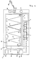
- the device according to the invention consists of an outer body (2) and an inner body (1) accessible through a front door (not shown).
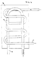
- the radiator system is attached under the metal base plate (5) of the inner body (1) in a closed room (4). It preferably consists of an aluminum plate (6) into which a tubular heating element (7) and a water pipe (8) made of stainless steel are cast.
- This radiator system (3) which is flat on the surface, is attached directly to the inner body (1) under the metal base plate (5), for example by screws.
- the tubular heater (7) heats the aluminum plate (6) and thus the metal base plate (5) of the inner body (1) and at the same time the water in the water pipe (8).
- the entire radiator system (3) is thermostatically controlled.
- the water pipe (8) is connected on the one hand to the portion container (19) and on the other hand via the line (11) to the spray system (12).
- the water in the water pipe (8) is heated, it rises thermally in the hose (11) to the spray system (12), where it is sprayed over the cloths (13).
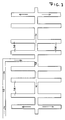
- the spray system (12) is attached to the ceiling (9) of the inner body (1) and, as shown in FIG. 3, consists of four parallel pipes (14) over each cloth underneath, to the right and left of the gable ( 16) of the respective cloth carrier (15).
- the tubes (14) have holes on their underside which allow the hot water to be sprayed onto the cloths underneath.
- the support structure (15) for the cloths (13) has the shape of several steep gable roofs (25) standing side by side, as shown in FIG.
- a frame preferably made of light metal, which can be pulled out of the inner body (1) on rails (26), supports the individual gable roofs (25), which consist of thin metal rods and so little access to hot spray water and hot steam possible hinder.
- the cloths are placed individually on such a roof and can then be optimally moistened from above due to the selected arrangement of the tubes (14).
- the upper edge (16) of the carrier (15) lies closely below the tubes (14).
- the hot water after switching on the device in the radiator system (3) and pressed purely thermally through the pipes (14) evaporates partly at the edges of the holes and reaches the wipes to be moistened partly as hot steam and partly as hot water. If the metered amount of water from the portion container (19) is used, the spraying from above ends automatically. The cloths then have the optimal level of moisture.
- the optimal amount of water can be identified on the portion container (19) by a corresponding marking (18) so that slight changes in the moisture level of the wipes are possible for the user by filling a smaller or larger amount into the portion container.
- the device preferably has a larger-volume storage container (22) which is filled via a fold-out filler neck (23) and can hold water for several heating processes.
- a tap (24) is attached between the storage container (22) and the portion container (19) and is opened and closed manually as soon as the water level in the position container (19) has reached the predetermined marking (18). It is also possible to automate this filling process in a suitable manner.
- the device is connected to the household electricity supply with a normal safety plug (28).
- the device preferably has an on / off switch (29). If the device is switched on, this can be indicated by a light indicator (30).
- a suitable signal can be used to indicate when the optimal wetting of the wipes has been reached by means of an acoustic signal. Since there are very many applications in which such an acoustic signal can have a disruptive effect, such as at conferences, the acoustic signal can also be switched off by a signal switch (31).
Landscapes
- Health & Medical Sciences (AREA)
- Public Health (AREA)
- Engineering & Computer Science (AREA)
- Food Science & Technology (AREA)
- Body Washing Hand Wipes And Brushes (AREA)
- Treatment Of Fiber Materials (AREA)
- Thermotherapy And Cooling Therapy Devices (AREA)
- Detail Structures Of Washing Machines And Dryers (AREA)
- Surface Heating Bodies (AREA)
Description
- Gegenstand der Erfindung ist eine Vorrichtung zum Heißbefeuchten von Gesichtstüchrern mit den Merkmalen gemäß den Ansprüchen.
- Befeuchtete und erhitzte Gesichtstücher, bei denen dem Dampf vorzugsweise ätherische Öle zugesetzt sind, sind ein bekanntes Mittel zur Erfrischung und werden gerne von Fluggesellschaften oder in Restaurants zur Erfrischung der Fluggäste oder Kunden ausgegeben.
- Üblicherweise werden die Handtücher angefeuchtet, gerollt und entweder in Aluminium-Folie eingewickelt im Heißluftherd oder in Kunststoff-Folie eingewickelt im Heißluft- oder Mikrowellenherd erhitzt, dann aus der Verpackung ausgewickelt und an die Geste ausgegeben.
- Das Ein- und Auswickeln ist umständlich und verbietet insbesondere den Einsatz solcher Gesichtstücher an fast allen Orten und bei Gelegenheiten, bei denen nicht Heißluftherde oder dergleichen vorhanden sind.
- In US-A-3 902 044 und US-4 084 080 werden Vorrichtungen vorgeschlagen, die mittels des in ihnen erzeugten Dampfes ein Erhitzen und Befeuchten von Tüchern erlauben sollen. Praktische Versuche haben jedoch ergeben, daß auf diese Weise die Tücher weder ausreichend erhitzt werden können noch ausreichende Mengen an Feuchtigkeit aufnehmen.
- US-A-4 947 026 zeigt eine Vorrichtung, bei der zum Befeuchten von Tüchern einerseits in einer unter den Tüchern angeordneten offenen Schale Wasser bis zum Kochen erhitzt wird und dadurch Wasserdampf entsteht, andererseits das heiße Wasser mittels einer Pumpe von oben auf die Tücher aufgetropft wird. Diese aufwendige Gestaltung ist für den praktischen Gebrauch ungeeignet, weil insbesondere einerseits der offene Wasserbehälter ein Verschmutzen des Wassers und ein Überschwappen des Wassers beim Anstoßen an die Vorrichtung nicht ausschließt und andererseits das aufwendige Pumpsystem mangels ausreichender zeitlicher Kontrolle nicht gewährleistet, daß die Tücher immer gleichmäßig und ausreichend befeuchtet, aber nicht zu naß werden. Zusätzlich muß das gesamte Wasser in dem Behälter, das die Heizschleife zunächst zumindest bedecken muß, zum Kochen gebracht werden.
- Ziel der vorliegenden Erfindung ist die Bereitstellung ines Geräts zum Heißbefeuchten von Tüchern, das die Nachteile bekannter Geräte vermeidet und leicht und sicher zu bedienen ist.
- Diese Aufgabe wird dadurch gelöst, daß die zu befeuchtenden Handtücher im Innenraum des Geräts auf steilgiebelähnliche Träger gelegt werden, unter der Bodenplatte des Innenraums des Geräts eine Heizvorrichtung für das Wasser angebracht ist, durch die einerseits die Bodenplatte beheizt wird und durch die andererseits das erhitzte Wasser einem unter der Decke des Innenraums angebrachten Rohrsystem ohne besondere Pumpvorrichtung zugeführt und dort auf die Handtücher gespritzt wird. Von den Handtüchern nicht aufgenommenes oder überschüssiges Wasser tropft auf die Bodenplatte zurück und verdampft von dort wieder. Das aufzuheizende Wasser wird einem, gegebenenfalls aus einem größeren Vorratsbehälter nachfüllbaren, Portionsbehälter entnommen, der seinerseits so dimensioniert ist, daß die darin enthaltene Wassermenge gerade für eine ausreichende Befeuchtung und Erhitzung ausreicht. Anhand der beigefügten Zeichnungen wird die Erfindung näher erläutert.
- Figur 1 zeigt eine Front-/Innenansicht des Geräts,
- Figur 2 ist eine perspektifische Darstellung des Trägersystems für die Tücher,
- Figur 3 ist eine schematische Darstellung des Sprühsystems,
- Figur 4 ist eine schematische Darstellung des Heizkörpersystems.
- Wie aus Figur 1 ersichtlich ist, besteht die erfindungsgemäße Vorrichtung aus einem Außenkörper (2) und einem, durch eine nicht gezeichnete Fronttüre zugänglichen Innenkörper (1). Unter der Metallbodenplatte (5) des Innenkörpers (1) ist in einem abgeschlossenen Raum (4) das Heizkörpersystem angebracht. Es besteht vorzugsweise aus einer Aluminiumplatte (6), in die ein Rohrheizkörper (7) und ein Wasserrohr (8) aus Edelstahl eingegossen sind. Dieses an der Oberfläche plane Heizkörpersystem (3) wird unter der Metallbodenplatte (5) des Innenkörpers (1) direkt an dieser befestigt, beispielsweise durch Schrauben. Der Rohrheizkörper (7) erhitzt die Aluminiumplatte (6) und damit die Metallbodenplatte (5) des Innenkörpers (1) und gleichzeitig das Wasser in dem Wasserrohr(8). Das gesamte Heizkörpersystem (3) ist thermostatisch geregelt.
- Das Wasserrohr (8) ist einerseits mit dem Portionsbehälter (19) und andererseits über die Leitung (11) mit dem Sprühsystem (12) verbunden. Wenn das Wasser in dem Wasserrohr (8) erhitzt wird, steigt es in den Schlauch (11) thermisch bis zum Sprühsystem (12) auf, wo es über den ausgelegten Tüchern (13) versprüht wird.
- Das Sprühsystem (12) ist an der Decke (9) des Innenkörpers (1) angebracht und besteht, wie Figur 3 zeigt, aus jeweils vier parallel verlaufenden Rohren (14) über jedem darunter befindlichen Tuch, und zwar rechts und links von dem Giebel (16) des jeweiligen Tuchträgers (15). Die Rohre (14) weisen an ihrer Unterseite Löcher auf, die es ermöglichen, daß das heiße Wasser auf die darunter befindlichen Tücher gesprüht wird.
- Die Trägerkonstruktion (15) für die Tücher (13) hat die Form mehrerer nebeneinander stehender, steiler Giebeldächer (25), wie Figur 2 zeigt. Ein vorzugsweise aus Leichtmetall bestehendes Gestell,das auf Schienen (26) aus dem Innenkörper (1) herausgezogen werden kann, trägt die einzelnen Giebeldächer (25), die aus dünnen Metallstäben bestehen und so sowohl den Zugang von heißem Sprühwasser wie heißem Dampf so wenig wie möglich behindern. Die Tücher werden einzeln auf ein solches Dach gelegt und können dann aufgrund der gewählten Anordnung der Rohre (14) optimal von oben befeuchtet werden Die Oberkante (16) der Träger (15) liegt dabei dicht unter den Rohren (14).
- Das nach dem Einschalten des Geräts im Heizkörpersystem (3) erhitzte und rein thermisch durch die Rohre (14) gepreßte heiße Wasser verdampft teilweise an den Lochrändern und erreicht teils als heißer Dampf, teils als heißes Wasser die zu befeuchtenden Tücher. Wenn die dosierte Wassermenge aus dem Portionsbehälter (19) verbraucht ist, endet das Besprühen von oben automatisch. Die Tücher haben dann den optimalen Feuchtigkeitsgrad erhalten. Die optimale Wassermenge kann auf dem Portionsbehälter (19) durch eine entsprechende Markierung (18) gekennzeichnet werden, so daß geringfügige Abwandlungen des Feuchtigkeitsgrades der Tücher durch Einfüllen einer kleineren oder größeren Menge in den Portionsbehälter für den Anwender möglich sind.
- Überschüssiges Wasser, das an den Tüchern vorbeispritzt, fällt auf die erhitzte Bodenplatte (5) und verdampft so. Auch das im Innenraum sich sammelnde Dampfkondensat gelangt auf die Bodenplatte und verdampft dort erneut. Wenn der Sprühvorgang von oben wegen des Aufbrauchs des Wasservorrats aus dem Portionsbehälter beendet ist, ist durch diesen Dampfkreislauf sichergestellt, daß die feuchten Tücher auch danach weiter heiß bleiben. Andererseits hat der heiße Dampf keinen Einfluß auf den Feuchtigkeitsgrad der Tücher mehr. Wenn dieser aufgrund des Besprühens einmal erreicht ist, bleibt er erhalten, ohne daß es weiterer Regelung seitens des Benutzers bedarf. Daß das Heizkörpersystem (3) thermostatisch auch in Abhängigkeit davon, ob das Rohr (8) noch Wasser enthält oder nicht, geregelt wird, ist selbstverständlich. Insgesamt ist eine Regelung per Hand weder für den Befeuchtungsprozess noch für den Vorgang des Erhitzens notwendig.
- Neben dem Portionsbehälter (19) weist die Vorrichtung vorzugsweise einen größervolumigen Vorratsbehälter (22) auf, der über einen ausklappbaren Einfüllstutzen (23) befüllt wird und Wasser für mehrere Heizvorgänge aufnehmen kann. Zwischen dem Vorratsbehälter (22) und dem Portionsbehälter (19) ist ein Hahn (24) angebracht, der manuell geöffnet und geschlossen wird, sobald der Wasserstand im Postionsbehälter (19) die vorgegebene Markierung (18) erreicht hat. Es ist auch möglich, diesen Befüllvorgang in geeigneter Weise zu automatisieren.
- Das Gerät wird mit einem normalen Sicherheitsstecker (28) an die Stromversorgung des Haushaltsstroms angeschlossen. Das Gerät weist vorzugsweise ein Ein-/Ausschalter (29) auf. Wenn das Gerät eingeschaltet ist, kann dies durch eine Leuchtanzeige (30) angezeigt werden. Durch geeignete Schaltung kann der Zeitpunkt des Erreichens der optimalen Befeuchtung der Tücher durch ein akustisches Signal angezeigt werden. Da es sehr viele Anwendungen gibt, bei denen ein solches akustisches Signal aber störend wirken kann, wie beispielsweise bei Konferenzen, kann durch einen Signalschalter (31) das akustische Signal auch ausgeschaltet werden.
Claims (4)
- Vorrichtung zum Heißbefeuchten von Gesichtstüchern mit einem beheizbaren Behälter für das Wasser, einer Anordnung zum Aufbringen von heißem Wasser auf die Tücher von oben bestehend aus einem an der Decke (9) des Innenraums (1) angebrachten Sprühsystem (12) und einem Träger für die Tücher, dadurch gekennzeichnet, daßa) das Erhitzen des Wassers in einem Heizkörpersystem (3), bestehend aus einem Heizkörper (7) und einem Wasserrohr(8), erfolgt, wobei das Wasserrohr einerseits mit einem Portionsbehälter (19) und andererseits mit einem Sprühsystem (12) verbunden ist,b) der Heizkörper von unten an der Bodenplatte (5) des Innenkörpers (1) der Vorrichtung angeordnet ist,c) die Träger (15) für die Tücher eine steilgiebelartige Form haben undd) das Sprühsystem (12) aus den Zuleitungen (12) sowie dem parallel zu den Giebeln (16) der Träger (15) rechts und links von diesen angeordneten Rohren (14) besteht, wobei die Rohre an ihrer Unterseite Auslassöffnungen aufweisen.
- Vorrichtung nach Anspruch 1, dadurch gekennzeichnet, daß der Heizkörper (7) die Form eines Rohrheizkörpers hat und zusammen mit dem Wasserrohr (8) in eine oben plane Aluminiumplatte (6) eingegossen ist.
- Vorrichtung nach einem der Ansprüche 1 oder 2, dadurch gekennzeichnet, daß die Träger (15) aus dünnen Metallstäben bestehen und auf einem Metallrahmen befestigt sind, der auf Schienen (26) aus dem Innenkörper(1) herausgezogen werden kann.
- Vorrichtung nach einem oder merherer der Ansprüche 1 bis 3, dadurch gekennzeichnet, daß zur Befüllung des Portionsbehälters (19) ein Vorratsbehälter (22) vorgesehen und in der Verbindungsleitung zwischen beiden ein Absperrhahn (24) angeordnet ist.
Priority Applications (9)
| Application Number | Priority Date | Filing Date | Title |
|---|---|---|---|
| EP92112622A EP0579856B1 (de) | 1992-07-23 | 1992-07-23 | Vorrichtung zum Heissbefeuchten von Gesichtstüchern |
| DE59203482T DE59203482D1 (de) | 1992-07-23 | 1992-07-23 | Vorrichtung zum Heissbefeuchten von Gesichtstüchern. |
| ES92112622T ES2078607T3 (es) | 1992-07-23 | 1992-07-23 | Dispositivo para el humedecimiento en caliente de pañuelos para refrescar el rostro. |
| DK92112622.3T DK0579856T3 (da) | 1992-07-23 | 1992-07-23 | Apparat til varmbefugtning af ansigtsklude |
| AT92112622T ATE126979T1 (de) | 1992-07-23 | 1992-07-23 | Vorrichtung zum heissbefeuchten von gesichtstüchern. |
| JP23494592A JPH0678860A (ja) | 1992-07-23 | 1992-09-02 | オシボリを加熱・加湿する装置 |
| US07/944,910 US5296681A (en) | 1991-01-15 | 1992-09-15 | Apparatus for hot moistening face-towels |
| TW082103608A TW225584B (de) | 1992-07-23 | 1993-05-10 | |
| GR950402782T GR3017678T3 (en) | 1992-07-23 | 1995-10-06 | Device for heating and moistening face towels. |
Applications Claiming Priority (1)
| Application Number | Priority Date | Filing Date | Title |
|---|---|---|---|
| EP92112622A EP0579856B1 (de) | 1992-07-23 | 1992-07-23 | Vorrichtung zum Heissbefeuchten von Gesichtstüchern |
Publications (2)
| Publication Number | Publication Date |
|---|---|
| EP0579856A1 EP0579856A1 (de) | 1994-01-26 |
| EP0579856B1 true EP0579856B1 (de) | 1995-08-30 |
Family
ID=8209838
Family Applications (1)
| Application Number | Title | Priority Date | Filing Date |
|---|---|---|---|
| EP92112622A Expired - Lifetime EP0579856B1 (de) | 1991-01-15 | 1992-07-23 | Vorrichtung zum Heissbefeuchten von Gesichtstüchern |
Country Status (8)
| Country | Link |
|---|---|
| EP (1) | EP0579856B1 (de) |
| JP (1) | JPH0678860A (de) |
| AT (1) | ATE126979T1 (de) |
| DE (1) | DE59203482D1 (de) |
| DK (1) | DK0579856T3 (de) |
| ES (1) | ES2078607T3 (de) |
| GR (1) | GR3017678T3 (de) |
| TW (1) | TW225584B (de) |
Families Citing this family (1)
| Publication number | Priority date | Publication date | Assignee | Title |
|---|---|---|---|---|
| CA2377031A1 (en) * | 1999-07-21 | 2001-02-01 | Gottlieb Moosbrugger | Individual moistening apparatus |
Family Cites Families (2)
| Publication number | Priority date | Publication date | Assignee | Title |
|---|---|---|---|---|
| US4947026A (en) * | 1989-04-17 | 1990-08-07 | Groom Raymond C | Towel heating and moistening |
| DE4100961C2 (de) * | 1991-01-15 | 1995-03-30 | Gunter Tschauder | Vorrichtung zum Dampfbefeuchten von Gesichtstüchern |
-
1992
- 1992-07-23 ES ES92112622T patent/ES2078607T3/es not_active Expired - Lifetime
- 1992-07-23 EP EP92112622A patent/EP0579856B1/de not_active Expired - Lifetime
- 1992-07-23 DK DK92112622.3T patent/DK0579856T3/da active
- 1992-07-23 AT AT92112622T patent/ATE126979T1/de active
- 1992-07-23 DE DE59203482T patent/DE59203482D1/de not_active Expired - Fee Related
- 1992-09-02 JP JP23494592A patent/JPH0678860A/ja not_active Withdrawn
-
1993
- 1993-05-10 TW TW082103608A patent/TW225584B/zh active
-
1995
- 1995-10-06 GR GR950402782T patent/GR3017678T3/el unknown
Also Published As
| Publication number | Publication date |
|---|---|
| TW225584B (de) | 1994-06-21 |
| ES2078607T3 (es) | 1995-12-16 |
| JPH0678860A (ja) | 1994-03-22 |
| EP0579856A1 (de) | 1994-01-26 |
| DK0579856T3 (da) | 1995-09-18 |
| ATE126979T1 (de) | 1995-09-15 |
| DE59203482D1 (de) | 1995-10-05 |
| GR3017678T3 (en) | 1996-01-31 |
Similar Documents
| Publication | Publication Date | Title |
|---|---|---|
| EP0869731A1 (de) | Kaffeemaschine | |
| EP1415580B1 (de) | Einrichtung zum Ableiten von Restdampf und Restwasser aus dem Heizer einer Heissgetränkmaschine, insbesondere Kaffeemaschine | |
| EP0340341B1 (de) | Begasungs-Brutschrank | |
| DE3839874A1 (de) | Lebensmittelkonditioniervorrichtung | |
| DE4040778A1 (de) | Mikroprozessorgesteuerte speisenbehandlungstruhe mit strahldampferzeuger und steuerungsablaeufen zur feuchtigkeitskompensation | |
| DE2226457A1 (de) | Einrichtung zur Endbearbeitung von Kleidungsstücken | |
| CH674941A5 (de) | ||
| DE3404892A1 (de) | Saunaofen | |
| EP0579856B1 (de) | Vorrichtung zum Heissbefeuchten von Gesichtstüchern | |
| DE1579508A1 (de) | Geheiztes Tellerausgabegeraet | |
| LU86330A1 (de) | Kombinierter dampferzeuger/saunaofen | |
| EP1102010A1 (de) | Ofen mit Dampferzeugungseinrichtung | |
| EP0807428A2 (de) | Verdampfersystem für Sauna-Anlagen | |
| DE868947C (de) | Kleiner elektrischer Dampfkessel mit Ausstroemduese zur stossweisen Erzeugung von reinen oder chemisch dosierten Daempfen fuer medizinische oder handwerkliche Zwecke | |
| CH682209A5 (en) | Heater to keep food hot on table | |
| DE2537429C3 (de) | Korrosionsprüfeinrichtung | |
| EP0363708A2 (de) | Heizvorrichtung für Medien | |
| DE2847830C2 (de) | Elektrischer Eierkocher | |
| DE3606051C2 (de) | Dampferzeuger für Dampfbäder, Inhalationsgeräte und Luftbefeuchter | |
| DE2112405A1 (de) | Vorrichtung zum Erzeugen metallisierter Laengsstreifen auf Folien | |
| DE4100961C2 (de) | Vorrichtung zum Dampfbefeuchten von Gesichtstüchern | |
| DE3429632A1 (de) | Heizgeraet | |
| DE3827562C2 (de) | ||
| DE878595C (de) | Verfahren und Maschine zum Auftragen von Klebstoffen | |
| DE2141209C2 (de) | Vorrichtung zum Beheizen von Lockenwicklern |
Legal Events
| Date | Code | Title | Description |
|---|---|---|---|
| PUAI | Public reference made under article 153(3) epc to a published international application that has entered the european phase |
Free format text: ORIGINAL CODE: 0009012 |
|
| AK | Designated contracting states |
Kind code of ref document: A1 Designated state(s): AT BE CH DE DK ES FR GB GR IT LI LU MC NL PT SE |
|
| 17P | Request for examination filed |
Effective date: 19940209 |
|
| 17Q | First examination report despatched |
Effective date: 19950220 |
|
| GRAA | (expected) grant |
Free format text: ORIGINAL CODE: 0009210 |
|
| AK | Designated contracting states |
Kind code of ref document: B1 Designated state(s): AT BE CH DE DK ES FR GB GR IT LI LU MC NL PT SE |
|
| REF | Corresponds to: |
Ref document number: 126979 Country of ref document: AT Date of ref document: 19950915 Kind code of ref document: T |
|
| REG | Reference to a national code |
Ref country code: DK Ref legal event code: T3 |
|
| GBT | Gb: translation of ep patent filed (gb section 77(6)(a)/1977) |
Effective date: 19950829 |
|
| ET | Fr: translation filed | ||
| REF | Corresponds to: |
Ref document number: 59203482 Country of ref document: DE Date of ref document: 19951005 |
|
| ITF | It: translation for a ep patent filed | ||
| REG | Reference to a national code |
Ref country code: ES Ref legal event code: FG2A Ref document number: 2078607 Country of ref document: ES Kind code of ref document: T3 |
|
| REG | Reference to a national code |
Ref country code: GR Ref legal event code: FG4A Free format text: 3017678 |
|
| SC4A | Pt: translation is available |
Free format text: 950830 AVAILABILITY OF NATIONAL TRANSLATION |
|
| PLBE | No opposition filed within time limit |
Free format text: ORIGINAL CODE: 0009261 |
|
| STAA | Information on the status of an ep patent application or granted ep patent |
Free format text: STATUS: NO OPPOSITION FILED WITHIN TIME LIMIT |
|
| 26N | No opposition filed | ||
| PGFP | Annual fee paid to national office [announced via postgrant information from national office to epo] |
Ref country code: PT Payment date: 19970314 Year of fee payment: 6 |
|
| PGFP | Annual fee paid to national office [announced via postgrant information from national office to epo] |
Ref country code: FR Payment date: 19970320 Year of fee payment: 6 |
|
| PGFP | Annual fee paid to national office [announced via postgrant information from national office to epo] |
Ref country code: SE Payment date: 19970610 Year of fee payment: 6 |
|
| PGFP | Annual fee paid to national office [announced via postgrant information from national office to epo] |
Ref country code: MC Payment date: 19970617 Year of fee payment: 6 |
|
| PGFP | Annual fee paid to national office [announced via postgrant information from national office to epo] |
Ref country code: GR Payment date: 19970630 Year of fee payment: 6 |
|
| PGFP | Annual fee paid to national office [announced via postgrant information from national office to epo] |
Ref country code: DK Payment date: 19970704 Year of fee payment: 6 |
|
| PGFP | Annual fee paid to national office [announced via postgrant information from national office to epo] |
Ref country code: AT Payment date: 19970708 Year of fee payment: 6 |
|
| PGFP | Annual fee paid to national office [announced via postgrant information from national office to epo] |
Ref country code: ES Payment date: 19970710 Year of fee payment: 6 Ref country code: CH Payment date: 19970710 Year of fee payment: 6 |
|
| PGFP | Annual fee paid to national office [announced via postgrant information from national office to epo] |
Ref country code: GB Payment date: 19970714 Year of fee payment: 6 |
|
| PGFP | Annual fee paid to national office [announced via postgrant information from national office to epo] |
Ref country code: BE Payment date: 19970730 Year of fee payment: 6 |
|
| PGFP | Annual fee paid to national office [announced via postgrant information from national office to epo] |
Ref country code: NL Payment date: 19970731 Year of fee payment: 6 |
|
| PGFP | Annual fee paid to national office [announced via postgrant information from national office to epo] |
Ref country code: LU Payment date: 19970908 Year of fee payment: 6 |
|
| PGFP | Annual fee paid to national office [announced via postgrant information from national office to epo] |
Ref country code: DE Payment date: 19970911 Year of fee payment: 6 |
|
| PG25 | Lapsed in a contracting state [announced via postgrant information from national office to epo] |
Ref country code: LU Free format text: LAPSE BECAUSE OF NON-PAYMENT OF DUE FEES Effective date: 19980723 Ref country code: GB Free format text: LAPSE BECAUSE OF NON-PAYMENT OF DUE FEES Effective date: 19980723 Ref country code: AT Free format text: LAPSE BECAUSE OF NON-PAYMENT OF DUE FEES Effective date: 19980723 |
|
| PG25 | Lapsed in a contracting state [announced via postgrant information from national office to epo] |
Ref country code: SE Free format text: LAPSE BECAUSE OF NON-PAYMENT OF DUE FEES Effective date: 19980724 Ref country code: ES Free format text: LAPSE BECAUSE OF NON-PAYMENT OF DUE FEES Effective date: 19980724 |
|
| PG25 | Lapsed in a contracting state [announced via postgrant information from national office to epo] |
Ref country code: LI Free format text: LAPSE BECAUSE OF NON-PAYMENT OF DUE FEES Effective date: 19980731 Ref country code: GR Free format text: LAPSE BECAUSE OF NON-PAYMENT OF DUE FEES Effective date: 19980731 Ref country code: DK Free format text: LAPSE BECAUSE OF NON-PAYMENT OF DUE FEES Effective date: 19980731 Ref country code: CH Free format text: LAPSE BECAUSE OF NON-PAYMENT OF DUE FEES Effective date: 19980731 Ref country code: BE Free format text: LAPSE BECAUSE OF NON-PAYMENT OF DUE FEES Effective date: 19980731 |
|
| PG25 | Lapsed in a contracting state [announced via postgrant information from national office to epo] |
Ref country code: MC Free format text: THE PATENT HAS BEEN ANNULLED BY A DECISION OF A NATIONAL AUTHORITY Effective date: 19980818 |
|
| BERE | Be: lapsed |
Owner name: TSCHAUDER GUNTER Effective date: 19980731 |
|
| PG25 | Lapsed in a contracting state [announced via postgrant information from national office to epo] |
Ref country code: PT Free format text: LAPSE BECAUSE OF NON-PAYMENT OF DUE FEES Effective date: 19990131 |
|
| PG25 | Lapsed in a contracting state [announced via postgrant information from national office to epo] |
Ref country code: NL Free format text: LAPSE BECAUSE OF NON-PAYMENT OF DUE FEES Effective date: 19990201 |
|
| REG | Reference to a national code |
Ref country code: CH Ref legal event code: PL |
|
| GBPC | Gb: european patent ceased through non-payment of renewal fee |
Effective date: 19980723 |
|
| EUG | Se: european patent has lapsed |
Ref document number: 92112622.3 |
|
| PG25 | Lapsed in a contracting state [announced via postgrant information from national office to epo] |
Ref country code: FR Free format text: LAPSE BECAUSE OF NON-PAYMENT OF DUE FEES Effective date: 19990331 |
|
| NLV4 | Nl: lapsed or anulled due to non-payment of the annual fee |
Effective date: 19990201 |
|
| PG25 | Lapsed in a contracting state [announced via postgrant information from national office to epo] |
Ref country code: DE Free format text: LAPSE BECAUSE OF NON-PAYMENT OF DUE FEES Effective date: 19990501 |
|
| REG | Reference to a national code |
Ref country code: FR Ref legal event code: ST |
|
| REG | Reference to a national code |
Ref country code: PT Ref legal event code: MM4A Free format text: LAPSE DUE TO NON-PAYMENT OF FEES Effective date: 19990131 |
|
| REG | Reference to a national code |
Ref country code: DK Ref legal event code: EBP |
|
| REG | Reference to a national code |
Ref country code: ES Ref legal event code: FD2A Effective date: 19990811 |
|
| PG25 | Lapsed in a contracting state [announced via postgrant information from national office to epo] |
Ref country code: IT Free format text: LAPSE BECAUSE OF NON-PAYMENT OF DUE FEES Effective date: 20050723 |