EP0578529B1 - Security device for electrical opening parts in vehicals with a drive cable for an opening member, in particular window winders and sliding roofs - Google Patents
Security device for electrical opening parts in vehicals with a drive cable for an opening member, in particular window winders and sliding roofs Download PDFInfo
- Publication number
- EP0578529B1 EP0578529B1 EP93401628A EP93401628A EP0578529B1 EP 0578529 B1 EP0578529 B1 EP 0578529B1 EP 93401628 A EP93401628 A EP 93401628A EP 93401628 A EP93401628 A EP 93401628A EP 0578529 B1 EP0578529 B1 EP 0578529B1
- Authority
- EP
- European Patent Office
- Prior art keywords
- traveller
- switch
- travellers
- motor
- movable member
- Prior art date
- Legal status (The legal status is an assumption and is not a legal conclusion. Google has not performed a legal analysis and makes no representation as to the accuracy of the status listed.)
- Expired - Lifetime
Links
Images


Classifications
-
- H—ELECTRICITY
- H01—ELECTRIC ELEMENTS
- H01H—ELECTRIC SWITCHES; RELAYS; SELECTORS; EMERGENCY PROTECTIVE DEVICES
- H01H35/00—Switches operated by change of a physical condition
- H01H35/006—Switches operated by mechanical overload condition, e.g. transmitted force or torque becoming too high
-
- E—FIXED CONSTRUCTIONS
- E05—LOCKS; KEYS; WINDOW OR DOOR FITTINGS; SAFES
- E05F—DEVICES FOR MOVING WINGS INTO OPEN OR CLOSED POSITION; CHECKS FOR WINGS; WING FITTINGS NOT OTHERWISE PROVIDED FOR, CONCERNED WITH THE FUNCTIONING OF THE WING
- E05F15/00—Power-operated mechanisms for wings
- E05F15/40—Safety devices, e.g. detection of obstructions or end positions
- E05F15/41—Detection by monitoring transmitted force or torque; Safety couplings with activation dependent upon torque or force, e.g. slip couplings
-
- E—FIXED CONSTRUCTIONS
- E05—LOCKS; KEYS; WINDOW OR DOOR FITTINGS; SAFES
- E05Y—INDEXING SCHEME RELATING TO HINGES OR OTHER SUSPENSION DEVICES FOR DOORS, WINDOWS OR WINGS AND DEVICES FOR MOVING WINGS INTO OPEN OR CLOSED POSITION, CHECKS FOR WINGS AND WING FITTINGS NOT OTHERWISE PROVIDED FOR, CONCERNED WITH THE FUNCTIONING OF THE WING
- E05Y2400/00—Electronic control; Power supply; Power or signal transmission; User interfaces
- E05Y2400/10—Electronic control
- E05Y2400/52—Safety arrangements
- E05Y2400/53—Wing impact prevention or reduction
- E05Y2400/54—Obstruction or resistance detection
- E05Y2400/55—Obstruction or resistance detection by using load sensors
- E05Y2400/552—Switches
-
- E—FIXED CONSTRUCTIONS
- E05—LOCKS; KEYS; WINDOW OR DOOR FITTINGS; SAFES
- E05Y—INDEXING SCHEME RELATING TO HINGES OR OTHER SUSPENSION DEVICES FOR DOORS, WINDOWS OR WINGS AND DEVICES FOR MOVING WINGS INTO OPEN OR CLOSED POSITION, CHECKS FOR WINGS AND WING FITTINGS NOT OTHERWISE PROVIDED FOR, CONCERNED WITH THE FUNCTIONING OF THE WING
- E05Y2900/00—Application of doors, windows, wings or fittings thereof
- E05Y2900/50—Application of doors, windows, wings or fittings thereof for vehicles
- E05Y2900/53—Application of doors, windows, wings or fittings thereof for vehicles characterised by the type of wing
- E05Y2900/55—Windows
Definitions
- the attraction force of the magnet 35 keeps the two carriages 6, 7 assembled as long as the force undergone by the carriage 7 carrying the movable member to be moved remains less than the attraction force of the magnet 35.
- this force exceeds said attractive force, the two carriages 6, 7 separate, the switch 17 changes state and the electrical supply circuit controls the reversal of the direction of rotation of the motor 5a.
- the security devices which have just been described with reference to Figs. 3 to 5 are said to have electrical memory, because for these embodiments it is necessary to provide an electrical diagram capable of keeping in memory the information that the system has triggered. , and therefore to react accordingly even when the effort has disappeared, to move the movable member (for example the window) to a given place, for example the low position to be sure that the obstacle has been completely released.
- the switch 56 is part of an electrical supply circuit capable of reversing the direction of rotation of the motor of the geared motor when the switch 56 changes state. This change of state is itself caused by the displacement of the magnet 49 from its position glued against the lower plate 52 to its position glued to the upper plate 51. In its position glued to the plate 52 (initial position) , the magnet pushes the rod of the switch 56, while in its position where it is glued to the plate 51, the contact between the magnet 49 and the switch 56 is interrupted.
- the tension spring 48 is prestressed and ensures the coupling of the two carriages 6, 7.
- the device will switch from its initial position, shown in FIG. 6, to its detection position if the elongation of the spring 48 is sufficient to that the rod 54 of the magnet 49 is driven in the upward movement by the carriage 6, and more precisely by the finger 53, the rod 54 then coming into abutment at the lower end of the slot 55.
- the latter has for function of authorizing a certain free movement of the carriage 6 relative to the carriage 7.
- the force on the movable member exceeds a certain predetermined limit, the rod 54 is driven by the carriage 6 and the magnet 49, which was glued against the plate 52, will come to stick against the plate 51.
- circuits of Fig. 11 and 12 are with mechanical memory, therefore not self-powered.
- the switches and their control circuits constitute a current loop ("fail safe”), which makes it possible to ensure that the circuit is operating correctly, and can put the system in safety.
- the different springs used for example 16 in Fig. 3, 48 in Fig. 6 ... are prestressed, unlike the springs in the above-mentioned prior documents (for example that of FR-A 2,461,085). They can thus be released from the effort threshold with extreme sensitivity, which constitutes an appreciable advantage compared to the known prior devices.
- the security system has the advantage of being relatively simple to manufacture and therefore inexpensive.
Description
La présente invention a pour objet un ouvrant électrique de véhicule selon le préambule de la revendication 1.The present invention relates to an electric vehicle opening according to the preamble of claim 1.
On sait qu'il existe actuellement trois types de lève-vitre sur les véhicules automobiles : les lève-vitre à câble crémaillère, les lève-vitre à câble torsadé (câble Bowden) et les lève-vitre à bras et secteur denté. L'invention concerne ces lève-vitre ainsi que d'autres ouvrants électriques présentant des conditions de fonctionnement similaires, tout particulièrement les toits ouvrants qui sont entraînés par des câbles.We know that there are currently three types of window regulators on motor vehicles: window regulators with rack cable, window regulators with twisted cable (Bowden cable) and window regulators with arms and toothed sector. The invention relates to these window regulators as well as to other electric windows having similar operating conditions, in particular the sun roofs which are driven by cables.
Quand un obstacle se trouve sur le parcours de fermeture de la vitre (ou du toit ouvrant), le système doit reconnaître la présence d'un phénomène anormal et, si l'effort sur la vitre ou le toit ouvrant dépasse une valeur limite, la vitre ne doit pas continuer sa trajectoire, mais s'arrêter et au moins libérer l'effort. Cette libération de l'effort peut être obtenue soit en libérant la vitre qui descend sous un faible effort ou sous l'effet de son propre poids si le frottement dans le joint latéral le permet, soit en inversant le mouvement de la vitre, qui est alors forcée à descendre.When an obstacle is on the closing path of the window (or sunroof), the system must recognize the presence of an abnormal phenomenon and, if the force on the window or the sunroof exceeds a limit value, the glass should not continue its trajectory, but stop and at least release the effort. This release of the force can be obtained either by releasing the window which descends under a low effort or under the effect of its own weight if the friction in the side seal allows it, or by reversing the movement of the window, which is then forced to descend.
Pour résoudre ce problème on a déjà proposé divers dispositifs de sécurité, électroniques et électromécaniques qui présentent, entre autres inconvénients, celui d'être relativement onéreux en raison de leur complexité. Ce coût de fabrication élevé est évidemment un obstacle à leur diffusion en grande série.To solve this problem, various safety devices have already been proposed, electronic and electromechanical, which have, among other disadvantages, that of being relatively expensive because of their complexity. This high manufacturing cost is obviously an obstacle to their dissemination in large series.
Par ailleurs, le US-A 2.130.764 et le FR-A 2.461.085 décrivent des dispositifs de sécurité pour des portes pivotantes dans lesquels des interrupteurs (switches) travaillent à la fermeture. De ce fait, si le câblage est défectueux, le système de sécurité ne fonctionne pas.Furthermore, US-A 2,130,764 and FR-A 2,461,085 describe security devices for pivoting doors in which switches work to close. Therefore, if the wiring is defective, the security system does not work.
En outre, ces deux dispositifs antérieurs comportent des ressorts dont la course de travail est importante, et donc la sensibilité au déclenchement faible.In addition, these two prior devices include springs whose working stroke is large, and therefore the sensitivity to tripping low.
L'invention a pour but de proposer un ouvrant électrique comportant un dispositif de sécurité électromécanique qui soit de fabrication simple, peu coûteuse, plus fiable et plus sensible que les dispositifs précités.The object of the invention is to propose an electric opening comprising an electromechanical safety device which is simple to manufacture, inexpensive, more reliable and more sensitive than the above-mentioned devices.
L'ouvrant visé par l'invention qui est conforme à la revendication 1, comprend des moyens électromécaniques d'accouplement et de détection d'effort entre un premier élément menant de ladite chaîne, et un second élément mené, supportant l'organe mobile, ces moyens étant agencés de manière à désaccoupler automatiquement les deux éléments menant et mené l'un de l'autre en cas de détection d'un effort dépassant une valeur prédéterminée, s'opposant à la course de la vitre.The opening referred to by the invention which is according to claim 1, comprises electromechanical means for coupling and force detection between a first driving element of said chain, and a second driven element, supporting the movable member, these means being arranged so as to automatically uncouple the two elements leading and led from each other in the event of detection of a force exceeding a predetermined value, opposing the travel of the window.
Ainsi, si dans un lève-vitre un obstacle s'interpose à la fermeture de la vitre, par exemple une main ou une autre partie du corps d'un passager, le système électromécanique détecte cet effort. Si ce dernier dépasse une certaine limite, le système réagit en inversant le sens de rotation du moteur, faisant ainsi descendre la vitre en libérant l'obstacle.Thus, if in an electric window an obstacle interposes the closing of the window, for example a hand or another part of the body of a passenger, the electromechanical system detects this effort. If the latter exceeds a certain limit, the system reacts by reversing the direction of rotation of the motor, thus lowering the window by releasing the obstacle.
Un tel ouvrant électrique est de structure relativement simple et peu onéreuse.Such an electric opening is of relatively simple and inexpensive structure.
D'autres particularités et avantages de l'invention apparaîtront au cours de la description qui va suivre, faite en référence aux dessins annexés qui en illustrent diverses formes de réalisations à titre d'exemples non limitatifs.Other features and advantages of the invention will appear during the description which follows, given with reference to the accompanying drawings which illustrate various embodiments thereof by way of non-limiting examples.
La figure 1 est une vue en élévation partielle simplifiée d'un ouvrant électrique du type à câble crémaillère conforme à l'invention.Figure 1 is a simplified partial elevational view of an electric opening of the rack cable type according to the invention.
La figure 2 est une vue en élévation partielle simplifiée d'un ouvrant constitué par un lève-vitre électrique selon l'invention, du type à câble Bowden.Figure 2 is a simplified partial elevational view of an opening constituted by an electric window regulator according to the invention, of the Bowden cable type.
Les figures 3, 4, 5, 6, sont des vues en élévation de quatre formes de réalisation du dispositif électromécanique de sécurité selon l'invention.Figures 3, 4, 5, 6 are elevation views of four embodiments of the electromechanical safety device according to the invention.
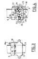
La figure 7 est une vue en coupe partielle suivant 9/9 de la Fig.6.Figure 7 is a partial sectional view along 9/9 of Fig.6.
La figure 8 est une vue en élévation analogue aux Fig.1 à 6 d'une cinquième forme de réalisation du dispositif de sécurité selon l'invention.Figure 8 is an elevational view similar to Fig.1 to 6 of a fifth embodiment of the safety device according to the invention.
Les figures 9, 10, 11 et 12 sont des schémas électriques illustrant quatre formes d'exécution possibles du circuit électrique d'alimentation des dispositifs de sécurité représentés aux Fig.1 à 8.Figures 9, 10, 11 and 12 are electrical diagrams illustrating four possible embodiments of the electrical circuit supplying the safety devices shown in Fig. 1 to 8.
L'ouvrant électrique 1 représenté à la Fig.1 est un lève-vitre du type à câble crémaillère 2 coulissant dans une gaine 3. Le câble 2 engrène avec un pignon 4 de sortie d'un moto-réducteur 5. Au câble crémaillère 3 est fixé un chariot menant 6 relié à un chariot mené 7 supportant une vitre 8, les deux chariots 6 et 7 pouvant coulisser le long d'un rail 9 de guidage.The electric opening 1 shown in Fig. 1 is a window regulator of the sliding
Ces chariots sont reliés par des moyens électromécaniques d'accouplement et de détection d'effort entre les deux chariots, dont plusieurs formes de réalisation seront décrites ci-après en référence aux Fig.3 à 15.These carriages are connected by electromechanical coupling and force detection means between the two carriages, several embodiments of which will be described below with reference to Figs. 3 to 15.
Le lève-vitre 11 représenté à la Fig.2 est du type à câble Bowden 12 enroulé autour de poulies 13 de renvoi et d'un tambour 14 solidaire de la roue dentée 15 du moto-réducteur 5. Au câble 12 est fixé le chariot 6, mécaniquement lié au chariot 7 supportant la vitre 8 par des moyens électromécaniques d'accouplement et de détection d'effort entre les deux chariots, selon l'un des modes de réalisation qui seront décrits ci-après.The window regulator 11 shown in FIG. 2 is of the Bowden
La Fig.3 illustre le schéma de fonctionnement le plus simple et le plus général de l'invention : les deux chariots 6, 7 sont accouplés par un élément élastique 16 précontraint de traction, constitué dans l'exemple représenté par un ressort hélicoïdal, et l'un des chariots, par exemple le chariot 6, est muni d'un interrupteur électrique 17 disposé en vis-à-vis du second chariot 7 de manière à pouvoir coopérer avec celui-ci. En raison de l'interposition du ressort 16 entre eux, les deux chariots 6, 7 sont distants d'un intervalle correspondant, mis à profit pour y disposer l'interrupteur 17. Des moyens de limitation du déplacement relatif des chariots 6, 7 sont prévus, par exemple comme représenté, un crochet 18 fixé à l'un des chariots (7 sur la Fig.3). Le crochet 18 s'étend le long de l'autre chariot 6 et son extrémité recourbée 18a permet de limiter le débattement entre les deux chariots.Fig.3 illustrates the simplest and most general operating diagram of the invention: the two
Si l'effort sur l'organe mobile porté par le chariot 7 augmente par suite de l'interposition d'un obstacle à la fermeture, le câble 2 ou 12 tend à tirer le chariot 6 vers le haut, tandis que l'effort sur l'organe mobile tend à pousser le chariot 7 vers le bas, le ressort 16 retenant les deux chariots entre eux. Un accroissement de l'effort sur l'organe mobile, donc entre les deux chariots 6, 7, provoque un allongement corrélatif du ressort 16. Tant que cet allongement ne dépasse pas une certaine limite, l'interrupteur 17 est dans un état déterminé : sur la Fig.3 il est en position poussée ou position départ. Au delà de cette limite, un effort supplémentaire, donc un allongement supplémentaire du ressort 16, libère suffisamment l'interrupteur 17 pour qu'il change d'état. Il suffit alors de disposer d'un circuit d'alimentation du moteur du moto-réducteur 5 qui, dans le cas où l'interrupteur 17 change d'état, inverse le sens de rotation du moteur et fait donc descendre l'organe mobile jusqu'au niveau voulu pour libérer l'obstacle.If the force on the movable member carried by the
Les Fig.9 et 10 montrent des exemples de circuit électriques d'alimentation appropriés, dits "à mémoire électrique". Il s'agit d'un circuit usuel de commande de lève-vitre (ou de toit ouvrant) connu en soi, comprenant un bouton 19 de montée/descente, alimenté par une batterie 21, et auquel se combinent deux relais 22, 23 d'inversion du sens de marche, commandés par l'interrupteur 17 de pesage et relié au moteur 5a du moto-réducteur 5. Dans ce genre de circuit, il suffit de maintenir l'interrupteur de pesage 17 juste le temps nécessaire pour basculer les relais. Ensuite, même si l'interrupteur 17 est relâché, les relais restent par un système d'autoalimentation dans cette position de détection et assurant la descente de la vitre jusqu'au point de réarmement. Ce circuit d'alimentation étant bien connu en soi, ne nécessite pas de description plus détaillée.Figs. 9 and 10 show examples of suitable electrical supply circuits, called "electric memory". It is a usual circuit for controlling the window regulator (or sunroof) known per se, comprising a
Le système de maintien des relais 22, 23 est alimenté tant que la pression sur le bouton 19 de commande est maintenue.The
Le circuit d'alimentation de la Fig.10 est une autre réalisation usuelle d'un circuit de commande, et ne diffère du circuit de la Fig.9 que par le fait qu'on amène continuellement le + et le - de la batterie 21 aux inverseurs des relais 22. L'alimentation du système de sécurité est donc indépendante de la position du bouton 19 de commande, de sorte qu'après la détection l'organe mobile descend, même après que le bouton 19 ait été relâché, et ce jusqu'à un point de réarmement. Le circuit de la Fig.10 est donc à mémoire électrique avec auto-alimentation.The supply circuit of Fig. 10 is another usual embodiment of a control circuit, and differs from the circuit of Fig. 9 only by the fact that the + and - of the
Le dispositif de sécurité de la Fig.4 comprend des moyens d'accouplement des deux chariots 6, 7 comportant un système à deux cliquets 24, 25 articulés sur des axes respectifs 26, 27 fixés à l'un des chariots, à savoir le chariot 7 dans l'exemple décrit. Ce dispositif d'accouplement comprend également un doigt 28 solidaire du chariot 6, portant un ergot terminal 29 engagé dans un bec 31 du cliquet 24, et un ressort 32 dont une extrémité est fixée en 33 au chariot 7 tandis que son extrémité est attachée en 34 au second cliquet 27. Ce dernier est ainsi sollicité élastiquement par le ressort 32, en appui contre le premier cliquet 24, de telle manière que le doigt 29 soit maintenu encliqueté dans le premier cliquet 24 tant que l'effort transmis au doigt 29 par le cliquet 24 reste inférieur à une valeur prédéterminée. L'un des chariots 6, 7, à savoir le chariot 6 dans l'exemple décrit, est équipé d'un interrupteur électrique 17, qui occupe l'intervalle entre les deux chariots et coopère avec le chariot 7 de façon à changer d'état lorsque l'effort précité dépasse ladite valeur prédéterminée et que le doigt 29 se dégage du cliquet 24.The safety device of FIG. 4 comprises means for coupling the two
L'interrupteur 17 fait partie d'un circuit électrique d'alimentation du moteur du moto-réducteur 5, qui peut être soit le circuit de la Fig.11 soit celui de la Fig.12, comme pour la sécurité illustrée à la Fig.3.The
La forme de réalisation du dispositif de sécurité illustré à la Fig.5 comprend, comme moyen d'accouplement entre les chariots 6, 7, un aimant 35 fixé à l'un des chariots et collé à une plaque ferromagnétique non représentée, fixée à l'autre chariot. Un interrupteur 17 est fixé à l'un des chariots 6, 7 dans leur intervalle de séparation, et fait partie d'un circuit d'alimentation électrique selon la Fig.11 ou la Fig.12.The embodiment of the safety device illustrated in FIG. 5 comprises, as a means of coupling between the
Le chariot 7 porte un crochet 18 de limitation du débattement entre les deux chariots, analogue à celui de la Fig.3.The
La force d'attraction de l'aimant 35 maintient les deux chariots 6, 7 assemblés tant que l'effort subi par le chariot 7 portant l'organe mobile à déplacer reste inférieur à la force d'attraction de l'aimant 35. Lorsque cet effort dépasse ladite force d'attraction, les deux chariots 6, 7 se séparent, l'interrupteur 17 change d'état et le circuit d'alimentation électrique commande l'inversion du sens de rotation du moteur 5a.The attraction force of the
Les dispositifs de sécurité qui viennent d'être décrits en référence aux Fig.3 à 5 sont dits à mémoire électrique, car pour ces modes de réalisation il convient de prévoir un schéma électrique capable de garder en mémoire l'information que le système a déclenchée, et donc de réagir en conséquence même quand l'effort a disparu, pour déplacer l'organe mobile (par exemple la vitre) à un endroit donné, par exemple la position basse pour être sûr que l'obstacle a été libéré complètement.The security devices which have just been described with reference to Figs. 3 to 5 are said to have electrical memory, because for these embodiments it is necessary to provide an electrical diagram capable of keeping in memory the information that the system has triggered. , and therefore to react accordingly even when the effort has disappeared, to move the movable member (for example the window) to a given place, for example the low position to be sure that the obstacle has been completely released.
On décrira maintenant en référence aux Fig.6 à 8 deux autres formes de réalisations de la sécurité selon l'invention, dans lesquelles celle-ci a une mémoire "mécanique". Ceci signifie que même quant l'effort n'est plus supérieur à la limite prédéterminée, par exemple après l'intervention du système de sécurité et donc l'inversion du mouvement de l'organe mobile, le système garde en mémoire le fait que le phénomène du dépassement de l'effort a eu lieu. La position de débrayage reste alors jusqu'au moment où l'on va délibérément réarmer le dispositif, donc le remettre en position de départ.There will now be described with reference to FIGS. 6 to 8 two other embodiments of security according to the invention, in which the latter has a "mechanical" memory. This means that even when the effort is no longer greater than the predetermined limit, for example after the intervention of the safety system and therefore the reversal of the movement of the movable member, the system keeps in mind that the phenomenon of exceeding the effort took place. The declutching position then remains until the device is deliberately reset, so put it back in the starting position.
Les Fig.6 et 7 montrent une sécurité dans laquelle les moyens d'accouplement des chariots 6, 7 comprennent un ressort 48 de traction reliant les chariots 6, 7. L'un de ceux-ci, par exemple le chariot 7 portant l'organe mobile, est pourvu d'un aimant 49 déplaçable entre deux positons stables par des moyens d'entraînement et de guidage portés par le chariot 6. L'aimant peut se déplacer entre deux plaques 51, 52 de matériau ferromagnétique fixées sur le chariot 7, à un écartement l'une de l'autre approprié de part et d'autre de l'élément 49.Fig. 6 and 7 show a safety device in which the coupling means of the
Les moyens d'entraînement et de guidage de l'aimant 49 comprennent, dans l'exemple représenté, un doigt 53 saillant du chariot 6, s'étendant en vis-à-vis de l'aimant 49, lequel est muni d'une tige 54 pouvant coulisser dans une fente 55 de guidage ménagée dans le doigt 54. Les deux positions stables de l'aimant 49 sont celles où il est collé à l'une ou l'autre des deux plaques 51 et 52. L'aimant 49 coopère de plus avec un interrupteur électrique 56 qui peut prendre deux états correspondant chacun à l'une des positions stables de l'aimant 49 : la première position stable étant celle où les deux chariots 6, 7 sont accouplés comme représenté à la Fig.8, et sa seconde position stable étant celle où ils restent accouplés, mais plus éloignés l'un de l'autre, après détection d'un effort supérieur à une valeur prédéterminée. L'interrupteur 56 fait partie d'un circuit électrique d'alimentation capable d'inverser le sens de rotation du moteur du moto-réducteur lorsque l'interrupteur 56 change d'état. Ce changement d'état est lui même provoqué par le déplacement de l'aimant 49 de sa position collée contre la plaque inférieure 52 jusqu'à sa position collée à la plaque supérieure 51. Dans sa position collée à la plaque 52 (position initiale), l'aimant pousse la tige de l'interrupteur 56, tandis que dans sa position où il est collé à la plaque 51, le contact entre l'aimant 49 et l'interrupteur 56 est interrompu.The drive and guide means of the
La position de l'interrupteur 56 informe donc dans quel état se trouve le système de sécurité.The position of the
Le ressort de traction 48 est précontraint et assure l'accouplement des deux chariots 6, 7. Le dispositif va basculer de sa position initiale, représentée à la Fig.6, dans sa position de détection si l'allongement du ressort 48 est suffisant pour que la tige 54 de l'aimant 49 soit entraînée dans le mouvement de montée par le chariot 6, et plus précisément par le doigt 53, la tige 54 venant alors en butée à l'extrémité inférieure de la fente 55. Cette dernière a pour fonction d'autoriser un certain débattement libre du chariot 6 par rapport au chariot 7. Ainsi, dès que l'effort sur l'organe mobile (vitre ou toit ouvrant), dépasse une certaine limite prédéterminée, la tige 54 est entraînée par le chariot 6 et l'aimant 49, qui était collé contre la plaque 52, va venir se coller contre la plaque 51. En même temps l'aimant 49 libère l'interrupteur 56 qui change d'état. A partir de ce moment, le circuit électrique d'alimentation, dont fait partie l'interrupteur 56, et qui peut être soit celui de la Fig.11, soit celui de la Fig.12, va inverser le sens de rotation du moteur du moto-réducteur 5. Le chariot 6 va donc être poussé vers le bas, tandis que la fente 55 permet à l'aimant 49 de rester dans sa position de détection, collé à la plaque 51, malgré le renversement du sens du mouvement.The
La Fig.11 représente un circuit usuel de commande d'ouvrant électrique comprenant comme les circuits des Fig.9 et 10, un bouton de commande 19 alimenté par la batterie 21, et deux relais 22, 23. Ce circuit ne nécessite donc pas de description détaillée. Tant que l'interrupteur de pesage 56 est en position de détection, les bobines 23 d'excitation des relais 22 sont alimentées, la descente se poursuivant sans qu'on ait besoin de maintenir la pression sur le bouton de commande 19. En effet, une fois la détection faite par le changement d'état de l'interrupteur 56 provoqué par le déplacement de l'aimant 49, l'interrupteur 56 reste dans son nouvel état jusqu'au moment où on "réarme volontairement" le système. Par conséquent le circuit électrique maintient l'interrupteur 56 dans sa position après la détection, même après le renversement du mouvement et donc suppression de l'effort.Fig.11 shows a usual electrical opening control circuit comprising like the circuits of Fig.9 and 10, a
Le circuit de la Fig.12 est similaire à celui de la Fig.11, mais il est de plus équipé d'un pont 57 de diodes qui alimente les relais 22, 23. Si on cesse d'appuyer sur le bouton 19, le système s'arrête et l'organe mobile cesse de descendre, car les bornes + des relais 22 ne sont plus alimentées, compte tenu de la disposition des diodes du pont 57. Comme les circuits électriques précédents, le circuit de la Fig.12 est connu en soi et ne nécessite donc pas de description détaillée.The circuit of Fig.12 is similar to that of Fig.11, but it is further equipped with a
Les circuits des Fig.11 et 12 sont à mémoire mécanique, donc non autoalimentés.The circuits of Fig. 11 and 12 are with mechanical memory, therefore not self-powered.
Dans la forme de réalisation de la sécurité de la Fig.8, l'accouplement des deux chariots 6, 7 est assuré par un ressort 58 précontraint de traction et l'un des deux chariots, par exemple le chariot 7, est équipé d'une pièce 59 articulée autour d'un axe 61. La pièce 59 coopère avec un interrupteur électrique 56 et est sollicitée par un ressort 62, dont une extrémité est fixée au chariot 7, vers une position correspondant à un premier état de l'interrupteur 56. Le chariot 6 est muni d'un doigt 70 dont l'extrémité coopère avec la pièce 59 afin de maintenir cette dernière, contre la force de rappel du ressort 62, dans une position angulaire correspondant au second état de l'interrupteur 56, comme représenté à la Fig.8. Le maintien de la pièce 59 et de l'interrupteur 56 dans cet état est assuré tant que l'élément élastique 58 ne subit pas un allongement supérieur à celui correspondant à une valeur prédéterminée. L'interrupteur 56 fait partie d'un circuit d'alimentation du motoréducteur 5 capable d'inverser le sens de rotation de celui-ci lorsque l'interrupteur 56 change d'état, afin de libérer l'organe mobile. Ce circuit électrique peut être soit celui de la Fig.11 soit celui de la Fig.12.In the embodiment of the security of FIG. 8, the coupling of the two
Ainsi, si les deux chariots 6, 7 s'éloignent d'une distance trop grande consécutivement à un allongement du ressort 58 lui même provoqué par l'interposition d'un obstacle entre l'organe mobile et le cadre qui l'entoure, la pièce 59 va être libérée de tout contact avec le doigt 70 qui s'escamote et donc va pivoter autour de l'axe 61 en libérant l'interrupteur 56. Ce dernier change d'état et le système électrique de la Fig.11 ou de la Fig.12 inverse le sens de rotation du moteur.Thus, if the two
Les réalisations de la sécurité à une seule position stable (Fig.3 à 5) n'ont pas de mémoire mécanique car elles n'ont qu'une seule position stable, et doivent donc être associées aux circuits des Fig.9 et 10. Les réalisations des Fig.6 à 8 ont deux positions stables, donc une mémoire mécanique, et sont de ce fait associées aux circuits des Fig.11 ou 12, non autoalimentés.Safety realizations with a single stable position (Fig. 3 to 5) have no mechanical memory because they have only one stable position, and must therefore be associated with the circuits of Fig. 9 and 10. The embodiments of Fig.6 to 8 have two stable positions, therefore a mechanical memory, and are therefore associated with the circuits of Fig.11 or 12, not self-powered.
Dans les divers modes de réalisation de l'invention, les interrupteurs et leurs circuits de commande constituent une boucle de courant ("fail safe"), qui permet de s'assurer que le circuit fonctionne correctement, et peuvent mettre le système en sécurité.In the various embodiments of the invention, the switches and their control circuits constitute a current loop ("fail safe"), which makes it possible to ensure that the circuit is operating correctly, and can put the system in safety.
Par ailleurs, les différents ressorts utilisés, par exemple 16 sur la Fig.3, 48 sur la Fig.6... sont précontraints, contrairement aux ressorts des documents antérieurs précités (par exemple celui du FR-A 2.461.085). Ils peuvent ainsi se libérer à partir du seuil d'effort avec une extrême sensibilité, ce qui constitue un avantage appréciable par rapport aux dispositifs antérieurs connus.Furthermore, the different springs used, for example 16 in Fig. 3, 48 in Fig. 6 ... are prestressed, unlike the springs in the above-mentioned prior documents (for example that of FR-A 2,461,085). They can thus be released from the effort threshold with extreme sensitivity, which constitutes an appreciable advantage compared to the known prior devices.
L'invention est susceptible de diverses variantes d'exécution. Ainsi il est évident notamment que la disposition relative des éléments d'accouplement et de détection d'effort sur les chariots 6 et 7 peut être inversée par rapport à celles représentées. De même un seul cliquet convenablement agencé peut remplacer les deux cliquets 24 et 25 de la Fig.4.The invention is susceptible of various variant embodiments. Thus it is evident in particular that the relative arrangement of the coupling and force detection elements on the
Dans les divers modes de réalisation de l'invention, le système de sécurité présente l'avantage d'être de fabrication relativement simple et donc peu onéreuse.In the various embodiments of the invention, the security system has the advantage of being relatively simple to manufacture and therefore inexpensive.
Claims (8)
- Electric opener for vehicles, comprising a motor (5a), a movable member (8) which can be moved by a cable, a kinematic chain for moving the cable, and a safety device comprising electromechanical coupling and load-detection means (16, 17...; 24, 25, 28, 17...) between a first, driving element (6) of the said chain and a second driven element (7) supporting the movable member, these means being arranged so as to disconnect the two driving and driven elements from one another automatically in the event of the detection of a load exceeding a predetermined value opposing the travel of the movable member, characterized in that the electromechanical coupling and load-detection means (16, 17, 22, 23..) are formed between a first, driving traveller (6) fixed to the cable (9) and a second, driven traveller (7) fixed to the movable member, these means being arranged so as to disconnect the two travellers from one another automatically in the event of the detection of the said load exceeding a predetermined value.
- Electric opener according to Claim 1, characterized in that the two travellers (6, 7) are coupled by a resilient element (16) prestressed in tension, one (6) of the travellers having an electrical switch (17) which is associated with the second traveller (7) so as to change state when the aforementioned load exceeds the said predetermined value and the resilient element undergoes an extension corresponding to the distance between the travellers, the switch forming part of an electrical motor-supply circuit which can reverse the sense of rotation of the motor in order to release the movable member when the switch changes state (Fig. 3).
- Electric opener according to Claim 1, characterized in that the said coupling means include a system with two catches (24, 25) articulated on respective pins (26, 27) fixed to one (7) of the travellers (6, 7), a finger (28) fixed to the other traveller (6) and engaged in a notch (31) of a first catch (24), and a spring (32) of which one end is fixed to the traveller carrying the catches and the other end is fixed to the second catch (25) which it urges into abutment against the first catch (24) so that the finger is kept locked in the first catch as long as the load transmitted to the finger by the first catch remains below the said predetermined value, one (6) traveller having an electrical switch (17) associated with the second traveller (7) so as to change state when the aforementioned load exceeds the said predetermined value and the finger is released from the system of catches, the switch forming part of an electric motor-supply circuit which can reverse the sense of rotation of the motor in order to release the movable member when the switch changes state (Fig. 4).
- Electric opener according to Claim 1, characterized in that the coupling means comprise a magnet (35) which is placed between armatures fixed to the travellers (6, 7) and the force of attraction of which keeps the two travellers together, whereas the load-detection means comprise an electrical switch (17) carried by one traveller (6) and associated with the second traveller so as to change state when the aforementioned load exceeds the said predetermined value the switch forming part of an electrical motor-supply circuit which can reverse the sense of rotation of the motor in order to release the movable member when the switch changes state (Fig. 5).
- Electric opener according to Claim 1, characterized in that the coupling means comprise a resilient element (48) prestressed in tension and connecting the two travellers (6, 7), one traveller (7) having a magnet (49) which can be moved between two stable positions by entrainment and guide means (53, 55) carried by the other traveller (6), this magnet cooperating with an electrical switch (56) which can adopt two states each corresponding to one of the stable positions of the magnet, the first stable position being that in which the two travellers (6, 7) are coupled and the second stable position being that in which they are disconnected after the detection of a load greater than the said predetermined value, the switch forming part of a supply circuit of the motor (5a), which can reverse the sense of rotation of the motor in order to release the movable member when the switch (56) changes state (Figs. 6-7).
- Electric opener according to Claim 5, characterized in that the means for entraining and guiding the magnet (35) comprise a finger (53) projecting from one (6) of the travellers (6, 7) and extending opposite the magnet which has a rod (54) sliding in a guide slot (55) formed in the finger, the stable positions of the magnet being determined by two plates (51, 52) of ferromagnetic material fixed to the traveller (7) carrying the magnet at a suitable distance on either side of the latter (Figs. 6-7).
- Electric opener according to Claim 1, characterized in that the coupling means comprise a resilient element (58) prestressed in tension and connecting the two travellers (6, 7), one traveller (7) being equipped with an element (59) which is articulated to this traveller, cooperates with an electrical switch (56), and is urged by a spring (62) towards a position corresponding to a first state of the switch, the second traveller (6) having a finger (70) cooperating with the said articulated element in order to keep the latter in an angular position corresponding to the second state of the switch, against the biasing force of the spring, as long as the resilient element does not undergo an extension greater than that corresponding to the said predetermined value, the switch forming part of an electrical supply circuit of the motor (5a), which can reverse the sense of rotation of the motor in order to release the movable member when the switch changes state (Fig. 8).
- Electric opener according to any one of Claims 1 to 4, characterized in that means are provided for limiting the relative movement of the travellers (6, 7), for example, a hook (18) fixed to one of the travellers and extending along the other traveller in order to limit its clearance relative to the traveller carrying the hook.
Priority Applications (1)
| Application Number | Priority Date | Filing Date | Title |
|---|---|---|---|
| EP96105244A EP0724279B1 (en) | 1992-07-10 | 1993-06-24 | Window winder for vehicles with oscillating arm and toothed sector |
Applications Claiming Priority (2)
| Application Number | Priority Date | Filing Date | Title |
|---|---|---|---|
| FR929208620A FR2693589B1 (en) | 1992-07-10 | 1992-07-10 | Safety device for electric vehicle openings, of the type with a drive cable for a movable member, in particular window glass and sunroofs. |
| FR9208620 | 1992-07-10 |
Related Child Applications (2)
| Application Number | Title | Priority Date | Filing Date |
|---|---|---|---|
| EP96105244.6 Division-Into | 1993-06-24 | ||
| EP96105244A Division EP0724279B1 (en) | 1992-07-10 | 1993-06-24 | Window winder for vehicles with oscillating arm and toothed sector |
Publications (2)
| Publication Number | Publication Date |
|---|---|
| EP0578529A1 EP0578529A1 (en) | 1994-01-12 |
| EP0578529B1 true EP0578529B1 (en) | 1997-03-12 |
Family
ID=9431817
Family Applications (2)
| Application Number | Title | Priority Date | Filing Date |
|---|---|---|---|
| EP93401628A Expired - Lifetime EP0578529B1 (en) | 1992-07-10 | 1993-06-24 | Security device for electrical opening parts in vehicals with a drive cable for an opening member, in particular window winders and sliding roofs |
| EP96105244A Expired - Lifetime EP0724279B1 (en) | 1992-07-10 | 1993-06-24 | Window winder for vehicles with oscillating arm and toothed sector |
Family Applications After (1)
| Application Number | Title | Priority Date | Filing Date |
|---|---|---|---|
| EP96105244A Expired - Lifetime EP0724279B1 (en) | 1992-07-10 | 1993-06-24 | Window winder for vehicles with oscillating arm and toothed sector |
Country Status (8)
| Country | Link |
|---|---|
| US (1) | US5461826A (en) |
| EP (2) | EP0578529B1 (en) |
| JP (1) | JPH06167167A (en) |
| BR (1) | BR9302821A (en) |
| CA (1) | CA2100120A1 (en) |
| DE (2) | DE69323778T2 (en) |
| FR (1) | FR2693589B1 (en) |
| MX (1) | MX9304139A (en) |
Families Citing this family (21)
| Publication number | Priority date | Publication date | Assignee | Title |
|---|---|---|---|---|
| IT1273093B (en) * | 1994-03-30 | 1997-07-04 | Capricorno Srl | SAFETY DEVICE FOR ELECTRIC WINDOWS OF VEHICLES |
| DE4420008C1 (en) * | 1994-06-08 | 1995-05-24 | Ford Werke Ag | Draw cord window raiser, esp. for road vehicles |
| US5595025A (en) * | 1995-05-01 | 1997-01-21 | Excel Industries, Inc. | Window regulator assembly |
| DE19618853C1 (en) * | 1996-05-10 | 1997-08-14 | Brose Fahrzeugteile | Motorised window drive with electronic anti-jamming protection e.g. for motor vehicles |
| GB2319805A (en) * | 1996-11-29 | 1998-06-03 | Btr Sealing Systems | Safety system for automotive window moving systems |
| FR2765613B1 (en) * | 1997-07-04 | 1999-09-17 | Rockwell Lvs | ELECTRIC WINDOW REGULATOR FOR MOTOR VEHICLE PROVIDED WITH AN ANTI-PINCH SYSTEM |
| US5960849A (en) * | 1997-08-13 | 1999-10-05 | Gmi Holdings, Inc. | Cable slack detector |
| US6243022B1 (en) | 1998-09-09 | 2001-06-05 | Honda Giken Kogyo Kabushiki Kaisha | Remote control device using two-way communication for a vehicle opening system |
| JP3931453B2 (en) * | 1998-11-06 | 2007-06-13 | アイシン精機株式会社 | Window door opening and closing device for vehicle sliding door |
| US6051945A (en) * | 1999-01-25 | 2000-04-18 | Honda Giken Kogyo Kabushiki Kaisha | Anti-pinch safety system for vehicle closure device |
| ATE333140T1 (en) * | 1999-11-02 | 2006-08-15 | Hans-Peter Loeffler | POWERFUL DETECTOR WITH TORQUE SWITCH |
| US6922031B2 (en) * | 2003-06-17 | 2005-07-26 | Arvinmeritor Technology, Llc | Door actuation system with helical cable |
| US20050093330A1 (en) * | 2003-11-04 | 2005-05-05 | Hoffman Lawrence A. | Power drives |
| JP4573887B2 (en) * | 2008-08-08 | 2010-11-04 | 三井金属鉱業株式会社 | Window regulator |
| US8069611B2 (en) * | 2009-05-12 | 2011-12-06 | Honda Motor Co., Ltd. | Door pane position sensor assembly |
| US20130219794A1 (en) * | 2010-11-08 | 2013-08-29 | Yachiyo Industry Co., Ltd. | Window regulator |
| EP2639393B1 (en) * | 2010-11-08 | 2019-09-11 | Yachiyo Industry Co., Ltd. | Window regulator |
| CN110462156A (en) * | 2017-03-31 | 2019-11-15 | 株式会社本田阿克塞斯 | Device for opening and closing vehicle door |
| CN108756572B (en) * | 2018-06-27 | 2020-07-03 | 温州如剑环保科技有限公司 | Anti-clamping device for automobile window |
| CN111270943A (en) * | 2020-02-14 | 2020-06-12 | 蒋利群 | Intelligent window opening robot for left and right sliding windows |
| CN113044687B (en) * | 2021-01-28 | 2022-09-20 | 艾陌极智能装备(深圳)有限公司 | Hanging basket steel wire rope damage detection device with stopping function |
Family Cites Families (11)
| Publication number | Priority date | Publication date | Assignee | Title |
|---|---|---|---|---|
| US2044712A (en) * | 1933-07-27 | 1936-06-16 | Monroe John Edgar | Automatic overload release clutch |
| US2130764A (en) * | 1937-09-30 | 1938-09-20 | Nat Pneumatic Co | Combined motor mechanism and control switch therefor |
| US2649300A (en) * | 1947-12-26 | 1953-08-18 | Electric Auto Lite Co | Window lifting mechanism |
| US2817512A (en) * | 1955-03-10 | 1957-12-24 | Gen Motors Corp | Window regulator safety device |
| US2883183A (en) * | 1958-04-21 | 1959-04-21 | Gen Motors Corp | Vehicle window actuators |
| DE1630492A1 (en) * | 1967-08-16 | 1971-05-13 | Fichtel & Sachs Ag | Gear, especially for sliding roofs, window lifters or the like. of motor vehicles |
| BE727619A (en) * | 1969-01-29 | 1969-07-01 | ||
| DE2028195A1 (en) * | 1970-06-09 | 1971-12-16 | Dr Ing h c F Porsche KG, 7000 Stuttgart Zuffenhausen | Switching device for electrically operated window panes of vehicles, in particular of motor vehicles |
| GB2107387B (en) * | 1979-07-04 | 1984-08-01 | Firmaframe Nominees Pty Ltd | Improved mechanism for stopping the drive or reversing the drive of motors of roller shutter doors |
| DE2928315C2 (en) * | 1979-07-13 | 1986-06-26 | Gebr. Bode & Co, 3500 Kassel | Anti-pinch device for a vehicle door operated by a rotating column |
| DE3215203A1 (en) * | 1982-04-23 | 1983-10-27 | Fraunhofer-Gesellschaft zur Förderung der angewandten Forschung e.V., 8000 München | Window lifter, especially for motor vehicles |
-
1992
- 1992-07-10 FR FR929208620A patent/FR2693589B1/en not_active Expired - Fee Related
-
1993
- 1993-06-24 EP EP93401628A patent/EP0578529B1/en not_active Expired - Lifetime
- 1993-06-24 DE DE69323778T patent/DE69323778T2/en not_active Expired - Fee Related
- 1993-06-24 DE DE69308660T patent/DE69308660T2/en not_active Expired - Fee Related
- 1993-06-24 EP EP96105244A patent/EP0724279B1/en not_active Expired - Lifetime
- 1993-07-02 US US08/087,835 patent/US5461826A/en not_active Expired - Fee Related
- 1993-07-08 CA CA002100120A patent/CA2100120A1/en not_active Abandoned
- 1993-07-09 MX MX9304139A patent/MX9304139A/en unknown
- 1993-07-09 BR BR9302821A patent/BR9302821A/en not_active Application Discontinuation
- 1993-07-12 JP JP5171562A patent/JPH06167167A/en active Pending
Also Published As
| Publication number | Publication date |
|---|---|
| EP0724279A3 (en) | 1996-10-16 |
| MX9304139A (en) | 1994-04-29 |
| FR2693589A1 (en) | 1994-01-14 |
| EP0724279B1 (en) | 1999-03-03 |
| EP0724279A2 (en) | 1996-07-31 |
| CA2100120A1 (en) | 1994-01-11 |
| DE69308660D1 (en) | 1997-04-17 |
| BR9302821A (en) | 1994-02-22 |
| JPH06167167A (en) | 1994-06-14 |
| DE69323778D1 (en) | 1999-04-08 |
| FR2693589B1 (en) | 1994-09-30 |
| US5461826A (en) | 1995-10-31 |
| EP0578529A1 (en) | 1994-01-12 |
| DE69323778T2 (en) | 1999-07-29 |
| DE69308660T2 (en) | 1997-11-13 |
Similar Documents
| Publication | Publication Date | Title |
|---|---|---|
| EP0578529B1 (en) | Security device for electrical opening parts in vehicals with a drive cable for an opening member, in particular window winders and sliding roofs | |
| EP0300840B1 (en) | Thief- and tamper-proof device to prevent operation of a door-lock and lock used therewith | |
| EP2616616B1 (en) | Vehicle door handle comprising an inertial mass and a fuse | |
| EP3581742B1 (en) | Door flush handle and method of operating the same | |
| FR2746718A1 (en) | Vehicle with electronic control system for operating vehicle e.g. sliding door, and door lock | |
| EP0057338B1 (en) | Control device for a powered sliding panel of a vehicle, especially for a window-lift | |
| CH688006A5 (en) | Shift actuator of a closing element moving at least approximately vertically. | |
| EP0581623B1 (en) | Safety device for electric cable window raiser of a vehicle | |
| EP1621712A1 (en) | Anti-pinch system | |
| EP0578534A1 (en) | Safety device for electrically operated vehicle closures, in particular window raisers and open roofs and closure incorporating this device | |
| EP0159238B1 (en) | Electromechanical lock control, and vehicle door lock provided therewith | |
| EP1476628A1 (en) | Closure system for motor vehicle motorized trunk | |
| EP0579518B1 (en) | Electric vehicle window actuator employing a cable sliding along a guide rail | |
| WO1999001637A1 (en) | Motor vehicle power-operated window lift equipped with anti-pinch system | |
| EP0819204B1 (en) | Utility door with a safety system | |
| EP1724428B1 (en) | Automatic operating mechanism of a light sliding door with at least one movable wing | |
| EP0102263B1 (en) | Electric lock for a vehicle door | |
| EP1093947B1 (en) | Blind with a powered rolling mechanism, with selective coupling of the winding tube with the motor means | |
| EP1525598B1 (en) | Device for controlling a motorized shutter | |
| EP1383980B1 (en) | Self-contained motor-operated assembly for driving a sliding gate | |
| FR2873150A1 (en) | Sliding door opening and closing controlling mechanism, has transmission belt with ends connected with main open spring and secondary spring, where stiffness of main spring is greater than that of secondary spring | |
| EP1612360A1 (en) | Control device of a motorised sliding window, in particular for a driver's cab of railway material or the like | |
| FR3007571A1 (en) | ELECTROMECHANICAL ACTUATOR AND METHOD OF USING THE ELECTROMECHANICAL ACTUATOR | |
| FR2855545A1 (en) | Door leaf locking device for vehicle, has actuator with returning unit that returns movable part of electric motor to unlocking position in absence of supply from motor, where part moves to locking position on powering of motor | |
| FR2494242A2 (en) | Safety braking system for electric lift cabin - includes centrifugal brake linked to cable drum and controlled by cabin position sensors to control rate of descent |
Legal Events
| Date | Code | Title | Description |
|---|---|---|---|
| PUAI | Public reference made under article 153(3) epc to a published international application that has entered the european phase |
Free format text: ORIGINAL CODE: 0009012 |
|
| AK | Designated contracting states |
Kind code of ref document: A1 Designated state(s): DE ES FR GB IT SE |
|
| 17P | Request for examination filed |
Effective date: 19940630 |
|
| 17Q | First examination report despatched |
Effective date: 19951030 |
|
| GRAG | Despatch of communication of intention to grant |
Free format text: ORIGINAL CODE: EPIDOS AGRA |
|
| RAP1 | Party data changed (applicant data changed or rights of an application transferred) |
Owner name: ROCKWELL LIGHT VEHICLE SYSTEMS - FRANCE, EN ABREGE |
|
| GRAH | Despatch of communication of intention to grant a patent |
Free format text: ORIGINAL CODE: EPIDOS IGRA |
|
| GRAH | Despatch of communication of intention to grant a patent |
Free format text: ORIGINAL CODE: EPIDOS IGRA |
|
| GRAA | (expected) grant |
Free format text: ORIGINAL CODE: 0009210 |
|
| ITF | It: translation for a ep patent filed |
Owner name: BARZANO' E ZANARDO ROMA S.P.A. |
|
| AK | Designated contracting states |
Kind code of ref document: B1 Designated state(s): DE ES FR GB IT SE |
|
| DX | Miscellaneous (deleted) | ||
| PG25 | Lapsed in a contracting state [announced via postgrant information from national office to epo] |
Ref country code: ES Free format text: THE PATENT HAS BEEN ANNULLED BY A DECISION OF A NATIONAL AUTHORITY Effective date: 19970312 |
|
| REF | Corresponds to: |
Ref document number: 69308660 Country of ref document: DE Date of ref document: 19970417 |
|
| GBT | Gb: translation of ep patent filed (gb section 77(6)(a)/1977) |
Effective date: 19970513 |
|
| PG25 | Lapsed in a contracting state [announced via postgrant information from national office to epo] |
Ref country code: SE Effective date: 19970612 |
|
| PG25 | Lapsed in a contracting state [announced via postgrant information from national office to epo] |
Ref country code: GB Free format text: LAPSE BECAUSE OF NON-PAYMENT OF DUE FEES Effective date: 19970624 |
|
| PLBE | No opposition filed within time limit |
Free format text: ORIGINAL CODE: 0009261 |
|
| STAA | Information on the status of an ep patent application or granted ep patent |
Free format text: STATUS: NO OPPOSITION FILED WITHIN TIME LIMIT |
|
| GBPC | Gb: european patent ceased through non-payment of renewal fee |
Effective date: 19970624 |
|
| PG25 | Lapsed in a contracting state [announced via postgrant information from national office to epo] |
Ref country code: DE Free format text: LAPSE BECAUSE OF NON-PAYMENT OF DUE FEES Effective date: 19980303 |
|
| 26N | No opposition filed | ||
| PGFP | Annual fee paid to national office [announced via postgrant information from national office to epo] |
Ref country code: FR Payment date: 20010621 Year of fee payment: 9 |
|
| PG25 | Lapsed in a contracting state [announced via postgrant information from national office to epo] |
Ref country code: FR Free format text: LAPSE BECAUSE OF NON-PAYMENT OF DUE FEES Effective date: 20030228 |
|
| REG | Reference to a national code |
Ref country code: FR Ref legal event code: ST |
|
| PG25 | Lapsed in a contracting state [announced via postgrant information from national office to epo] |
Ref country code: IT Free format text: LAPSE BECAUSE OF NON-PAYMENT OF DUE FEES;WARNING: LAPSES OF ITALIAN PATENTS WITH EFFECTIVE DATE BEFORE 2007 MAY HAVE OCCURRED AT ANY TIME BEFORE 2007. THE CORRECT EFFECTIVE DATE MAY BE DIFFERENT FROM THE ONE RECORDED. Effective date: 20050624 |