EP0578298B1 - Druckregler für Fluide - Google Patents
Druckregler für Fluide Download PDFInfo
- Publication number
- EP0578298B1 EP0578298B1 EP19930201773 EP93201773A EP0578298B1 EP 0578298 B1 EP0578298 B1 EP 0578298B1 EP 19930201773 EP19930201773 EP 19930201773 EP 93201773 A EP93201773 A EP 93201773A EP 0578298 B1 EP0578298 B1 EP 0578298B1
- Authority
- EP
- European Patent Office
- Prior art keywords
- fuel
- pressure
- nozzle
- burner
- pressure chamber
- Prior art date
- Legal status (The legal status is an assumption and is not a legal conclusion. Google has not performed a legal analysis and makes no representation as to the accuracy of the status listed.)
- Expired - Lifetime
Links
Images
Classifications
-
- F—MECHANICAL ENGINEERING; LIGHTING; HEATING; WEAPONS; BLASTING
- F23—COMBUSTION APPARATUS; COMBUSTION PROCESSES
- F23N—REGULATING OR CONTROLLING COMBUSTION
- F23N5/00—Systems for controlling combustion
- F23N5/18—Systems for controlling combustion using detectors sensitive to rate of flow of air or fuel
- F23N5/187—Systems for controlling combustion using detectors sensitive to rate of flow of air or fuel using electrical or electromechanical means
-
- F—MECHANICAL ENGINEERING; LIGHTING; HEATING; WEAPONS; BLASTING
- F23—COMBUSTION APPARATUS; COMBUSTION PROCESSES
- F23N—REGULATING OR CONTROLLING COMBUSTION
- F23N1/00—Regulating fuel supply
- F23N1/02—Regulating fuel supply conjointly with air supply
- F23N1/025—Regulating fuel supply conjointly with air supply using electrical or electromechanical means
-
- G—PHYSICS
- G05—CONTROLLING; REGULATING
- G05D—SYSTEMS FOR CONTROLLING OR REGULATING NON-ELECTRIC VARIABLES
- G05D16/00—Control of fluid pressure
- G05D16/028—Controlling a pressure difference
-
- G—PHYSICS
- G05—CONTROLLING; REGULATING
- G05D—SYSTEMS FOR CONTROLLING OR REGULATING NON-ELECTRIC VARIABLES
- G05D16/00—Control of fluid pressure
- G05D16/20—Control of fluid pressure characterised by the use of electric means
- G05D16/2006—Control of fluid pressure characterised by the use of electric means with direct action of electric energy on controlling means
- G05D16/2013—Control of fluid pressure characterised by the use of electric means with direct action of electric energy on controlling means using throttling means as controlling means
-
- F—MECHANICAL ENGINEERING; LIGHTING; HEATING; WEAPONS; BLASTING
- F23—COMBUSTION APPARATUS; COMBUSTION PROCESSES
- F23N—REGULATING OR CONTROLLING COMBUSTION
- F23N5/00—Systems for controlling combustion
- F23N5/18—Systems for controlling combustion using detectors sensitive to rate of flow of air or fuel
- F23N2005/181—Systems for controlling combustion using detectors sensitive to rate of flow of air or fuel using detectors sensitive to rate of flow of air
-
- F—MECHANICAL ENGINEERING; LIGHTING; HEATING; WEAPONS; BLASTING
- F23—COMBUSTION APPARATUS; COMBUSTION PROCESSES
- F23N—REGULATING OR CONTROLLING COMBUSTION
- F23N2225/00—Measuring
- F23N2225/04—Measuring pressure
-
- F—MECHANICAL ENGINEERING; LIGHTING; HEATING; WEAPONS; BLASTING
- F23—COMBUSTION APPARATUS; COMBUSTION PROCESSES
- F23N—REGULATING OR CONTROLLING COMBUSTION
- F23N2227/00—Ignition or checking
- F23N2227/36—Spark ignition, e.g. by means of a high voltage
-
- F—MECHANICAL ENGINEERING; LIGHTING; HEATING; WEAPONS; BLASTING
- F23—COMBUSTION APPARATUS; COMBUSTION PROCESSES
- F23N—REGULATING OR CONTROLLING COMBUSTION
- F23N2227/00—Ignition or checking
- F23N2227/42—Ceramic glow ignition
-
- F—MECHANICAL ENGINEERING; LIGHTING; HEATING; WEAPONS; BLASTING
- F23—COMBUSTION APPARATUS; COMBUSTION PROCESSES
- F23N—REGULATING OR CONTROLLING COMBUSTION
- F23N2229/00—Flame sensors
-
- F—MECHANICAL ENGINEERING; LIGHTING; HEATING; WEAPONS; BLASTING
- F23—COMBUSTION APPARATUS; COMBUSTION PROCESSES
- F23N—REGULATING OR CONTROLLING COMBUSTION
- F23N2233/00—Ventilators
- F23N2233/06—Ventilators at the air intake
- F23N2233/08—Ventilators at the air intake with variable speed
-
- F—MECHANICAL ENGINEERING; LIGHTING; HEATING; WEAPONS; BLASTING
- F23—COMBUSTION APPARATUS; COMBUSTION PROCESSES
- F23N—REGULATING OR CONTROLLING COMBUSTION
- F23N2235/00—Valves, nozzles or pumps
- F23N2235/12—Fuel valves
- F23N2235/14—Fuel valves electromagnetically operated
-
- F—MECHANICAL ENGINEERING; LIGHTING; HEATING; WEAPONS; BLASTING
- F23—COMBUSTION APPARATUS; COMBUSTION PROCESSES
- F23N—REGULATING OR CONTROLLING COMBUSTION
- F23N2235/00—Valves, nozzles or pumps
- F23N2235/12—Fuel valves
- F23N2235/20—Membrane valves
-
- F—MECHANICAL ENGINEERING; LIGHTING; HEATING; WEAPONS; BLASTING
- F23—COMBUSTION APPARATUS; COMBUSTION PROCESSES
- F23N—REGULATING OR CONTROLLING COMBUSTION
- F23N2235/00—Valves, nozzles or pumps
- F23N2235/12—Fuel valves
- F23N2235/24—Valve details
-
- F—MECHANICAL ENGINEERING; LIGHTING; HEATING; WEAPONS; BLASTING
- F23—COMBUSTION APPARATUS; COMBUSTION PROCESSES
- F23N—REGULATING OR CONTROLLING COMBUSTION
- F23N5/00—Systems for controlling combustion
- F23N5/20—Systems for controlling combustion with a time program acting through electrical means, e.g. using time-delay relays
-
- Y—GENERAL TAGGING OF NEW TECHNOLOGICAL DEVELOPMENTS; GENERAL TAGGING OF CROSS-SECTIONAL TECHNOLOGIES SPANNING OVER SEVERAL SECTIONS OF THE IPC; TECHNICAL SUBJECTS COVERED BY FORMER USPC CROSS-REFERENCE ART COLLECTIONS [XRACs] AND DIGESTS
- Y10—TECHNICAL SUBJECTS COVERED BY FORMER USPC
- Y10T—TECHNICAL SUBJECTS COVERED BY FORMER US CLASSIFICATION
- Y10T137/00—Fluid handling
- Y10T137/7722—Line condition change responsive valves
- Y10T137/7781—With separate connected fluid reactor surface
- Y10T137/7782—With manual or external control for line valve
Definitions
- This invention relates to the control of fluid to a nozzle and, more particularly, to a fluid pressure regulator having a duty cycle controlled, solenoid valve for controlling fluid to a nozzle which is subject to varying downstream pressure and a pressure dependent feedback means for modifying the fluid pressure to account for variation in downstream pressure.
- One method of preheating catalytic converters involves the use of fuelled burner systems which combust gaseous or liquid fuel in an exhaust mounted burner for a short time following engine start-up.
- fuelled burner systems which combust gaseous or liquid fuel in an exhaust mounted burner for a short time following engine start-up.
- Such systems generally require a combustor mounted in a burner housing having an outlet in communication with engine exhaust gas.
- the burner requires a fuel supply and means such as a fuel injector or nozzle for introducing the fuel to the combustor.
- combustion air must be supplied and mixed with the fuel in a proportion which results in optimum fuel/air mixture for combustion.
- An ignition source such as a spark plug, ignites the fuel/air mixture in the combustor.
- the burner fuel supply is most conveniently an extension of the engine fuel supply and, consequently, should be configured so as not to compromise the operation of that system, or be affected by it.
- Substantially instantaneous ignition and reliable operation of the burner is a requirement and, as such, the fuel supply must be able to compensate rapidly to changes in pressure differential across the fuel discharge nozzle caused by exhaust back pressure variation and to changes in fuel supply pressure caused by changes in engine operation. It is desirable to render such back pressure and fuel pressure variations transparent to the burner allowing fuelling to occur in a manner consistent with the goals of the burner control strategy.
- an object of the present invention is to provide a fluid pressure regulator, for use with an exhaust gas burner, capable of supplying fuel to a fuel discharge nozzle in such a manner as to maintain a desired pressure differential across the nozzle regardless of exhaust back pressure variation on the downstream, or outlet side of the nozzle, and regardless of fuel supply pressure. Response to system changes must occur rapidly to permit fast and reliable ignition and operation of the burner.
- JP-A-57-169515 discloses a pressure regulator for a gas supply which includes the components disclosed in the pre-amble of claim 1.
- a fuel pressure regulator in accordance with the present invention is characterised by the features specified in the characterising portion of Claim 1.
- the present invention provides a solenoid actuated fuel pressure regulator capable of continuously modulating pressure differential relative to a predetermined input percent duty cycle.
- the present invention preferably also provides an electric pressure regulator having a minimum internal volume with no fuel recirculation, which can be reverse-purged following burner operation to prevent discharge of unburned fuel to the burner.
- the disclosed pressure regulator comprises a support structure, or housing, through which the fuel supply passes and in which is mounted a solenoid actuator.
- a spring biased valve resides in the fuel supply passage of the support structure and seats against a valve seat. The valve regulates fuel flow from the supply to the regulator.
- a solenoid driven actuator acts to unseat the valve, allowing fuel to flow into the pressure regulator and to a fuel discharge nozzle.
- the solenoid is pulse-width modulated at a variable duty cycle to adjust the fuel pressure to the nozzle in accordance with the burner control strategy.
- the location of the nozzle within the exhaust gas environment subjects it to variances in exhaust back pressure caused by changes in engine operation. Such back pressure variations, unless compensated for, will affect the fuel pressure differential across the nozzle and, therefore, the control of the burner.
- a fuel pressure control diaphragm assembly in communication with exhaust back pressure, acts to vary the degree of valve opening dependent upon the magnitude of exhaust back pressure acting on the nozzle.
- the fuel pressure control diaphragm is operative on the fuel control valve independently of the solenoid, allowing adjustment to the fuel supply as called for by the control algorithm, while rendering back pressure variations transparent to the goals of the burner controller and burner operation.
- variations in fuel supply pressure due to changing engine operation will act on the diaphragm to vary the degree of valve opening depending upon pressure changes, resulting in fuel supply pressure variations which are transparent to burner operation.
- a burner 10 for combusting a fuel, supplied from a source, and ejecting the burnt gases from the fuel into an exhaust stream 11, such as that from an internal combustion engine (not shown).
- the burner 10 is useful for adding heat to the exhaust gas stream for rapidly heating the catalyst in a catalytic converter 12 to which it is shown in operable communication.
- a blower 14 supplies combustion air to the burner 10 in a proportion required for optimal combustion of the supplied fuel.
- the fuel and air are mixed within the burner 10 and are ignited by an ignitor 16, such as a spark plug or glow plug.
- the fuel supply, blower 14 and ignitor 16 are controlled, during operation, by an electronic controller (ECM) 22 which issues commands consistent with the goals of the burner control strategy and based on information gathered from sensors such as differential pressure sensor 18, and flame detector 20.
- ECM electronic controller
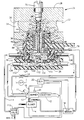
- the fluid pressure regulator designated generally as 26, is useful for this purpose.
- a support structure or fuel supply manifold 28 has a fuel passage 30 extending therethrough from an inlet 32 to an outlet 34.
- the fuel passage 30 is connected to a source of high pressure fuel (not shown), which in an automotive application may be the fuel supply for the vehicle internal combustion engine.
- the support structure 28 defines a housing for an electro-hydraulic pressure regulating valve 36, which is disposed in a stepped bore 38 and operates to regulate the fuel pressure across the fuel discharge nozzle 24.
- Stepped bore 38 includes a large diameter inner wall 40 and a small diameter inner wall 42 connected to the wall 40 by a shoulder 44 and extending from the shoulder 44 through the support structure 28 to form a through-bore which intersects and communicates at opening 43 with fuel passage 30.
- a solenoid 46 of the pressure regulating valve 26 is disposed within the large diameter inner wall 40 of stepped bore 38 and includes a cup-shaped outer pole piece 48 having an annular working surface 50.
- An inner pole piece 52 of the solenoid 46 includes a cylindrical, tubular stem portion 54 having an internal cylindrical bore 56 extending therethrough, and an outer cylindrical wall 58.
- the inner pole piece 52 further includes a flanged portion 60 having an annular land 62 extending about the upper end of internal cylindrical bore 56. The land 62 bears against the shoulder 44 at a location adjacent to the small diameter inner wall 42 thereby defining an inlet for fuel from the fuel passage 30 to the cylindrical inner bore 56 of the inner pole piece 52.
- Inner cylindrical bore 56 of the tubular stem portion 54 co-operates with land 62 to receive a valve seat 64.
- the valve seat may be a hardened insert such as is shown in the Figure, and is configured to cooperate with a valve 66 to regulate the flow of fuel from fuel passage 30 to the internal cylindrical bore 56.
- the valve 66 is biased towards a normally closed, seated position relative to valve seat 64 by spring 68 disposed within small diameter inner wall 42 of stepped bore 38.
- the biasing force exerted on valve 66 by spring 68 may be adjusted by rotating adjustment screw 70, located in a threaded portion of small diameter inner wall 42, and engaged with the end of the spring 68 remote from valve 66.
- the valve 66 has, in the preferred embodiment illustrated, a generally disc shaped configuration. It is, however, contemplated that the valve may have other configurations such as a spherical shape.
- An insulating bobbin 72 of the solenoid 46 is received on the outer cylindrical wall 58 of the stem portion 54 and abuts the flanged portion 60 of the inner pole piece 52.
- a coil 74 of the solenoid 46 is wound in conventional fashion on the bobbin 72, the coil being energizable through a pair of pin terminals 76 extending through an opening in outer pole piece 48.
- Solenoid 46 is encapsulated in body 78, which has an outer surface 80 configured to be closely received in the large diameter inner wall 40 of stepped bore 38.
- An annular spacer member 82 formed integrally with the body 78, extends from the lower surface thereof.
- the body 78 is preferably constructed of a rigid, fluid tight material having good resistance to degradation in a fuel environment, such as glass filled nylon.
- a resilient sealing member, such as O-ring 84, defines a fluid seal against fuel leakage from stepped bore 38 in fluid communication with fuel passage 30.
- a fuel regulator base member 86 has side walls 88, terminating in upper surface 90 and defining an inner wall 92 comprising a through-bore therein.
- Inner wall 92 has a shoulder 94 intermediate its length configured to closely receive the lower portion of solenoid body 78 with annular spacer member 82 in abutment with shoulder 94.
- a resilient seal ring 96 is seated between the inner wall 92 and the outer surface of the annular spacer member 82 to define a fluid seal therebetween.
- the upper surface 90 of the base member co-operates with corresponding channel 98 in support structure 28 to substantially enclose solenoid 46, as in a housing.
- Fuel regulator base member 86 has an opened lower portion 99 which is closed by a diaphragm assembly 100, secured in place by exhaust pressure manifold 102.
- the annular working surface 50 of outer pole piece 48, the opened lower portion 99 of base member 86, and the diaphragm assembly 100 cooperate to define fluid control pressure chamber 104.
- a control pressure port 106 formed in the base member 86, connects the pressure chamber 104 with the fuel discharge nozzle 24 through fuel conduit 108.
- purge port 110 formed through the bottom portion of the base member 86, connects the pressure chamber 104 with a purge valve 112 through fuel conduit 114.
- a magnetically permeable armature 116 is disposed in the fuel control pressure chamber 104.
- the armature 116 is configured as a substantially disc-shaped member and resides within the space defined by annular spacer member 82 of solenoid body 78.
- the armature 116 has an upper working surface 118 engaging push rod 120 which is loosely disposed within the cylindrical tubular stem portion 54 of inner pole piece 52.
- the push rod 120 extends between and contacts both the armature upper working surface 118 and the valve 66.
- Diaphragm assembly 100 has an upper surface 122 in communication with fuel control pressure chamber 104 and a lower surface 124 in communication with exhaust pressure chamber 126 in exhaust pressure manifold 102.
- the exhaust pressure manifold is connected through exhaust pressure port 128 to receive an exhaust pressure signal from exhaust gas burner 10.
- a rigid centre stop 130 is centrally disposed in diaphragm assembly 100 and is acted upon by a biasing means such as spring 132 which acts to urge the stop 130 upwardly, as viewed in the Figure, into contact with the lower working surface 134 of armature 116.
- the effect of the upwardly biased stop 130 against armature 116 is to bring the stop 130, armature 116, push rod 120, and valve 66 into contact with one another, allowing a force, representing a changing exhaust back pressure, to be transmitted directly to the valve member.
- valve 66 urges the push rod 120 and armature 116 downwardly, resulting in a maximum air gap between the upper working surface 118 of the armature 116 and the annular working surface 50 of outer pole piece 48. It is not desirable to have fuel present in the control pressure passage 104 or at the nozzle 24 when the burner 10 is not operating due to the high operating temperatures of an exhaust environment which may lead to fuel coking and subsequent nozzle failure.
- Spring 68 is sized so as to maintain valve 66 closed during periods of non-operation against the bias of diaphragm spring 132.
- Fuel in the fluid control pressure chamber 104 flows through control pressure port 106 and through fuel conduit 108 to nozzle 24 where it is injected into burner 10. If the coil 74 is energised for a sustained period, control pressure will eventually approach the supply pressure in fuel passage 30. If the coil 74 is alternately energised and de-energised, at selected frequencies corresponding to selected duty cycles of the solenoid 46 which represent a predetermined burner control strategy, then the control pressure will stabilise at an intermediate magnitude between the supply pressure and zero.
- the control of the solenoid coil 74 by the control module 22 is based largely on a predetermined control strategy as reflected in the control algorithm.
- the control module 22 is generally insensitive to variations in exhaust back pressure and fuel supply pressure, caused by changes in engine operation, which will affect the differential pressure across the nozzle 24 and, as a result, fuel delivery to the burner 10.
- the diaphragm assembly 100 is operable under the influence of such changes to modify the valve opening to adjust fuel flow thereby rendering such changes transparent to burner control and operation. As the exhaust back pressure increases, the diaphragm assembly 100 increases its upward force against the armature 116 thereby moving valve 66 further off valve seat 64 with a resulting increase in fuel pressure reflecting the changing back pressure downstream of nozzle 24.
- a decrease in the exhaust back pressure will lessen the effect of the diaphragm assembly 100 on valve lift, thereby lowering fuel pressure to adjust for a lowered back pressure at the nozzle 24.
- the diaphragm assembly 100 is acted on to lower its upward force on armature 116 thereby moving valve 66 towards valve seat 64 and decreasing flow to reflect the higher pressure.
- a decrease in supply pressure will be reflected in a lessening of downward force on the diaphragm assembly 100 with a resulting increase in valve lift.
- the diaphragm assembly 100 is able to alter the fuel pressure delivered to nozzle 24 on a real time basis which is independent of the control strategy.
- Termination of burner operation occurs through de-energization of solenoid coil 74 by the control module 22, causing the armature 116 to move in a downward direction, as viewed in the Figure, under the urging of biasing spring 68 and the supply fuel pressure from fuel passage 30 which acts on valve 66.
- the force exerted by spring 68 and the supply fuel pressure are sufficient to maintain the valve 66 in a closed, fuel-off position.
- the control module 22 opens purge valve 112 to vent control pressure chamber 104 and fuel conduit 108 to a vacuum source such as manifold vacuum, inducing fuel remaining in the fuel pressure regulator 26 and fuel conduit 108 to purge from the system through conduit 114 and purge port 110.
- the present invention discloses a solenoid controlled pneumatic-hydraulic differential pressure regulator for precise control of fluid to a nozzle situated in an environment of varying pressure.
- the solenoid responding to electrical signals from a control module, regulates the fluid through a valve in a manner consistent with a predetermined control strategy.
- a pressure dependent control means comprising a diaphragm assembly operably connected to the valve, adjusts fuel flow through the valve in response to changes in pressure across the nozzle and to changes in fuel supply pressure. Adjustment of flow by the pressure dependent control means occurs independently of, and transparent to, the control strategy of the electronic control module.
- the disclosed fuel pressure regulator includes a means for purging fluid from the regulator, nozzle, and associated conduits, following cessation of solenoid operation, in a manner which does not include ejection from the nozzle.
Landscapes
- Engineering & Computer Science (AREA)
- Physics & Mathematics (AREA)
- Fluid Mechanics (AREA)
- Chemical & Material Sciences (AREA)
- Combustion & Propulsion (AREA)
- Mechanical Engineering (AREA)
- General Engineering & Computer Science (AREA)
- General Physics & Mathematics (AREA)
- Automation & Control Theory (AREA)
- Magnetically Actuated Valves (AREA)
Claims (3)
- Ein Brennstoffdruckregler (26) zur Steuerung des Brennstoffdruckes zu einer Düse (24) in einem Brenner (10), mit einem Ventilgehäuse (28, 78, 86) mit einer Fluidsteuerdruckkammer (104), die mit der Düse wirkverbunden ist, wobei die Steuerdruckkammer mit einer Quelle von unter Druck stehendem Brennstoff (30) über einen Brennstoffeinlaß (32) im Gehäuse verbindbar ist; einem Ventilelement (66), das zwischen einer normal geschlossenen Position und einer geöffneten Position betätigbar ist, um unter Druck stehenden Brennstoff von dem Fluideinlaß zu der Steuerdruckkammer zu lassen; einem Solenoidmittel (46), das durch eine Steuerung (22) zur Betätigung des Ventilelements betätigbar ist; und einem Plattenventilelement (100), das mit dem Ventilelement wirkverbunden ist und betätigbar ist, um das Ventilelement in Richtung der normal geschlossenen Position oder der geöffneten Position unabhängig von dem Solenoidmittel und der Steuerung zu betätigen, wobei das Plattenventilelement eine erste Oberfläche (122) und eine zweite Oberfläche (124) hat, dadurch gegekennzeichnet, daß der Brenner (10) innerhalb eines Abgassystems einer Brennkraftmaschine angeordnet ist, die erste Oberfläche (122) in Verbindung mit dem unter Druck stehenden Brennstoff in der Steuerdruckkammer (104) ist, wobei ein ansteigender Brennstoffdruck in der Steuerdruckkammer das Plattenventilelement (100) betätigt, um das Ventilelement (66) in Richtung der normal geschlossenen Position zu bringen und dadurch die Zuführung von unter Druck stehendem Brennstoff zu der Steuerdruckkammer und zu der Düse zu verringern; und daß die zweite Oberfläche (124) mit einem Abgasgegendruck stromabwärts von der Düse (24) in Verbindung bringbar ist, wobei ein sich erhöhender Abgasgegendruck das Plattenventilelement (100) betätigt, um das Ventilelement in Richtung der geöffneten Position zu bewegen und dadurch die Zufuhr von unter Druck stehendem Brennstoff zu der Steuerdruckkammer und zu der Düse zu erhöhen, worin Änderungen in dem Brennstoffversorgungsdruck und in dem Abgasgegendruck transparent für die Steuerung des Brennstoffdruckes zu der Düse durch die Steuerung ist.
- Ein Brennstoffdruckregler wie in Anspruch 1 beansprucht, worin das Ventilelement (66) in die normal geschlossene Position durch ein Vorspannmittel (68) und durch den Druck des Brennstoffs am Fluideinlaß (32) vorgespannt ist.
- Ein Brennstoffdruckregler wie in Anspruch 1 oder Anspruch 2 beansprucht, mit weiterhin einem Reinigungsmittel (112), um eine Vakuumquelle mit der Steuerdruckkammer (104) und der Düse (24) zu verbinden, um aus diesen Brennstoff zu entfernen.
Applications Claiming Priority (2)
| Application Number | Priority Date | Filing Date | Title |
|---|---|---|---|
| US909488 | 1992-07-06 | ||
| US07/909,488 US5234024A (en) | 1992-07-06 | 1992-07-06 | Differential pressure regulator |
Publications (2)
| Publication Number | Publication Date |
|---|---|
| EP0578298A1 EP0578298A1 (de) | 1994-01-12 |
| EP0578298B1 true EP0578298B1 (de) | 1996-09-04 |
Family
ID=25427312
Family Applications (1)
| Application Number | Title | Priority Date | Filing Date |
|---|---|---|---|
| EP19930201773 Expired - Lifetime EP0578298B1 (de) | 1992-07-06 | 1993-06-21 | Druckregler für Fluide |
Country Status (3)
| Country | Link |
|---|---|
| US (1) | US5234024A (de) |
| EP (1) | EP0578298B1 (de) |
| DE (1) | DE69304451T2 (de) |
Families Citing this family (8)
| Publication number | Priority date | Publication date | Assignee | Title |
|---|---|---|---|---|
| US5353591A (en) * | 1993-08-19 | 1994-10-11 | General Motors Corporation | Exhaust heating control |
| US5353590A (en) * | 1993-08-19 | 1994-10-11 | General Motors Corporation | Exhaust heating control |
| EP0967439B1 (de) * | 1998-06-15 | 2008-09-24 | Toyota Jidosha Kabushiki Kaisha | Brennkraftmaschine mit einem Verbrennungsheizgerät |
| US6279539B1 (en) | 1999-04-20 | 2001-08-28 | Caterpillar Inc. | Hydraulically actuated fuel injector with cold start features |
| DE10026035C2 (de) * | 2000-05-25 | 2002-06-27 | Honeywell Bv | Regeleinrichtung für Gasbrenner |
| DE102005054733A1 (de) * | 2005-11-17 | 2007-05-24 | Robert Bosch Gmbh | Brenner zur Katalysatoraufheizung mit gesteuerter oder geregelter Kraftstoffzuführung |
| US8240328B2 (en) * | 2009-10-19 | 2012-08-14 | Luis Guillermo Ramirez-Diaz | Automatic fluid spill prevention and shut off safety valve |
| IT202200016665A1 (it) * | 2022-08-04 | 2024-02-04 | Sit Spa | Apparato di gestione di un flusso di un gas |
Family Cites Families (5)
| Publication number | Priority date | Publication date | Assignee | Title |
|---|---|---|---|---|
| FR1310619A (fr) * | 1961-10-17 | 1962-11-30 | Gen Thermique Procedes Brola | Dispositif de régulation et de sécurité pour brûleurs à gaz |
| US3994356A (en) * | 1975-06-06 | 1976-11-30 | Colt Industries Operating Corporation | Safety shut-off fuel system |
| US4645450A (en) * | 1984-08-29 | 1987-02-24 | Control Techtronics, Inc. | System and process for controlling the flow of air and fuel to a burner |
| US4693275A (en) * | 1986-11-28 | 1987-09-15 | General Motors Corporation | Electro-hydraulic pressure regulating valve |
| US4955350A (en) * | 1989-06-21 | 1990-09-11 | General Motors Corporation | Fuel injection |
-
1992
- 1992-07-06 US US07/909,488 patent/US5234024A/en not_active Expired - Fee Related
-
1993
- 1993-06-21 EP EP19930201773 patent/EP0578298B1/de not_active Expired - Lifetime
- 1993-06-21 DE DE69304451T patent/DE69304451T2/de not_active Expired - Fee Related
Also Published As
| Publication number | Publication date |
|---|---|
| DE69304451T2 (de) | 1997-01-23 |
| EP0578298A1 (de) | 1994-01-12 |
| DE69304451D1 (de) | 1996-10-10 |
| US5234024A (en) | 1993-08-10 |
Similar Documents
| Publication | Publication Date | Title |
|---|---|---|
| US6752135B2 (en) | Apparatus for air/fuel ratio control | |
| US6758233B2 (en) | High volume electronic gas regulator | |
| JP3914583B2 (ja) | デマンド燃料圧力調整器を具備したノーリターン燃料装置 | |
| US5785025A (en) | Fuel supply for international combustion engine | |
| JP2747428B2 (ja) | デマンド燃料圧レギュレータ | |
| EP0578298B1 (de) | Druckregler für Fluide | |
| EP1593833B1 (de) | Gaszufuhrsystem für eine Brennkraftmaschine mit einem durch einen Steuerdruck geregeltem Druckminderventil | |
| EP1596056B1 (de) | Gaszufuhrsystem für eine Brennkraftmaschine mit einem zum Ansaugkrümmer verbundenen Druckminderventil | |
| EP1593832B1 (de) | Gaszuführsystem für eine Brennkraftmaschine mit verbessertem Druckregler | |
| EP1593823B1 (de) | Gaszuführsystem für eine Brennkraftmaschine mit einem Druckablassventil und einem Druckregelmagnetventil | |
| CN101044313B (zh) | 燃料喷射阀 | |
| CA2041293A1 (en) | Burner devices | |
| US4393840A (en) | Fuel control system for automobile engine | |
| EP0496487B1 (de) | Emissionssteuerungssystem | |
| US3978836A (en) | Suction heat control unit in internal combustion engine | |
| AU2003278637B2 (en) | Method and apparatus for fuel injection systems | |
| US5184457A (en) | Valve assembly and method | |
| JPH06173785A (ja) | 内燃機関用排ガス再循環バルブを制御するためのアセンブリ | |
| JP7515230B1 (ja) | バーナ用燃料制御装置およびバーナ用燃料制御方法 | |
| SU1747723A1 (ru) | Устройство дл подачи дополнительного топлива в двухтопливный дизельный двигатель | |
| JPS61277832A (ja) | エンジンの空燃比制御装置 | |
| JPS62228635A (ja) | アルコ−ルを燃料とする内燃機関 | |
| JP2003269262A (ja) | 排出ガス再循環装置 | |
| JPH09105335A (ja) | ガスタービンの着火装置 | |
| JPH04339170A (ja) | ディーゼルエンジンの燃料噴射装置 |
Legal Events
| Date | Code | Title | Description |
|---|---|---|---|
| PUAI | Public reference made under article 153(3) epc to a published international application that has entered the european phase |
Free format text: ORIGINAL CODE: 0009012 |
|
| AK | Designated contracting states |
Kind code of ref document: A1 Designated state(s): DE FR GB |
|
| 17P | Request for examination filed |
Effective date: 19940131 |
|
| 17Q | First examination report despatched |
Effective date: 19950515 |
|
| GRAH | Despatch of communication of intention to grant a patent |
Free format text: ORIGINAL CODE: EPIDOS IGRA |
|
| GRAH | Despatch of communication of intention to grant a patent |
Free format text: ORIGINAL CODE: EPIDOS IGRA |
|
| GRAA | (expected) grant |
Free format text: ORIGINAL CODE: 0009210 |
|
| AK | Designated contracting states |
Kind code of ref document: B1 Designated state(s): DE FR GB |
|
| ET | Fr: translation filed | ||
| REF | Corresponds to: |
Ref document number: 69304451 Country of ref document: DE Date of ref document: 19961010 |
|
| PG25 | Lapsed in a contracting state [announced via postgrant information from national office to epo] |
Ref country code: GB Free format text: LAPSE BECAUSE OF NON-PAYMENT OF DUE FEES Effective date: 19970621 |
|
| PLBE | No opposition filed within time limit |
Free format text: ORIGINAL CODE: 0009261 |
|
| STAA | Information on the status of an ep patent application or granted ep patent |
Free format text: STATUS: NO OPPOSITION FILED WITHIN TIME LIMIT |
|
| 26N | No opposition filed | ||
| GBPC | Gb: european patent ceased through non-payment of renewal fee |
Effective date: 19970621 |
|
| PG25 | Lapsed in a contracting state [announced via postgrant information from national office to epo] |
Ref country code: FR Free format text: LAPSE BECAUSE OF NON-PAYMENT OF DUE FEES Effective date: 19980227 |
|
| PG25 | Lapsed in a contracting state [announced via postgrant information from national office to epo] |
Ref country code: DE Free format text: LAPSE BECAUSE OF NON-PAYMENT OF DUE FEES Effective date: 19980303 |
|
| REG | Reference to a national code |
Ref country code: FR Ref legal event code: ST |
|
| REG | Reference to a national code |
Ref country code: FR Ref legal event code: ST |