EP0578175B1 - Appareil de dialyse - Google Patents
Appareil de dialyse Download PDFInfo
- Publication number
- EP0578175B1 EP0578175B1 EP93110728A EP93110728A EP0578175B1 EP 0578175 B1 EP0578175 B1 EP 0578175B1 EP 93110728 A EP93110728 A EP 93110728A EP 93110728 A EP93110728 A EP 93110728A EP 0578175 B1 EP0578175 B1 EP 0578175B1
- Authority
- EP
- European Patent Office
- Prior art keywords
- clamp
- blood
- dialysis apparatus
- branch pipe
- dialyzer
- Prior art date
- Legal status (The legal status is an assumption and is not a legal conclusion. Google has not performed a legal analysis and makes no representation as to the accuracy of the status listed.)
- Expired - Lifetime
Links
Images


Classifications
-
- A—HUMAN NECESSITIES
- A61—MEDICAL OR VETERINARY SCIENCE; HYGIENE
- A61M—DEVICES FOR INTRODUCING MEDIA INTO, OR ONTO, THE BODY; DEVICES FOR TRANSDUCING BODY MEDIA OR FOR TAKING MEDIA FROM THE BODY; DEVICES FOR PRODUCING OR ENDING SLEEP OR STUPOR
- A61M1/00—Suction or pumping devices for medical purposes; Devices for carrying-off, for treatment of, or for carrying-over, body-liquids; Drainage systems
- A61M1/36—Other treatment of blood in a by-pass of the natural circulatory system, e.g. temperature adaptation, irradiation ; Extra-corporeal blood circuits
- A61M1/3621—Extra-corporeal blood circuits
- A61M1/3643—Priming, rinsing before or after use
-
- A—HUMAN NECESSITIES
- A61—MEDICAL OR VETERINARY SCIENCE; HYGIENE
- A61M—DEVICES FOR INTRODUCING MEDIA INTO, OR ONTO, THE BODY; DEVICES FOR TRANSDUCING BODY MEDIA OR FOR TAKING MEDIA FROM THE BODY; DEVICES FOR PRODUCING OR ENDING SLEEP OR STUPOR
- A61M1/00—Suction or pumping devices for medical purposes; Devices for carrying-off, for treatment of, or for carrying-over, body-liquids; Drainage systems
- A61M1/34—Filtering material out of the blood by passing it through a membrane, i.e. hemofiltration or diafiltration
- A61M1/342—Adding solutions to the blood, e.g. substitution solutions
- A61M1/3424—Substitution fluid path
- A61M1/3431—Substitution fluid path upstream of the filter
-
- A—HUMAN NECESSITIES
- A61—MEDICAL OR VETERINARY SCIENCE; HYGIENE
- A61M—DEVICES FOR INTRODUCING MEDIA INTO, OR ONTO, THE BODY; DEVICES FOR TRANSDUCING BODY MEDIA OR FOR TAKING MEDIA FROM THE BODY; DEVICES FOR PRODUCING OR ENDING SLEEP OR STUPOR
- A61M1/00—Suction or pumping devices for medical purposes; Devices for carrying-off, for treatment of, or for carrying-over, body-liquids; Drainage systems
- A61M1/36—Other treatment of blood in a by-pass of the natural circulatory system, e.g. temperature adaptation, irradiation ; Extra-corporeal blood circuits
- A61M1/3621—Extra-corporeal blood circuits
- A61M1/3643—Priming, rinsing before or after use
- A61M1/3644—Mode of operation
- A61M1/3646—Expelling the residual body fluid after use, e.g. back to the body
-
- A—HUMAN NECESSITIES
- A61—MEDICAL OR VETERINARY SCIENCE; HYGIENE
- A61M—DEVICES FOR INTRODUCING MEDIA INTO, OR ONTO, THE BODY; DEVICES FOR TRANSDUCING BODY MEDIA OR FOR TAKING MEDIA FROM THE BODY; DEVICES FOR PRODUCING OR ENDING SLEEP OR STUPOR
- A61M1/00—Suction or pumping devices for medical purposes; Devices for carrying-off, for treatment of, or for carrying-over, body-liquids; Drainage systems
- A61M1/36—Other treatment of blood in a by-pass of the natural circulatory system, e.g. temperature adaptation, irradiation ; Extra-corporeal blood circuits
- A61M1/3621—Extra-corporeal blood circuits
- A61M1/3643—Priming, rinsing before or after use
- A61M1/3644—Mode of operation
- A61M1/3652—Mode of operation using gas, e.g. air
Definitions
- the present invention relates to a dialysis apparatus which dialyses blood of a patient.
- the present inventors have developed the dialysis apparatus shown in Fig. 1 as a dialysis apparatus used in blood dialysis.
- a blood pump 4 is connected to a first pipe 3 which is coupled with a blood inlet 2 of a patient.
- An arterial-side chamber 6 is connected to the blood pump 4 through the medium of a second pipe 5.
- a dialyser 8 is connected to arterial chamber 6 through the medium of the third pipe 7.
- a venous-side chamber 10 is connected to dialyzer 8 through the medium of a fourth pipe 9.
- Venous-side chamber 10 is connected to blood outlet 12 through the medium of a fifth pipe 11.
- the first through fifth pipes 3 to 11 comprise the main piping.
- a supplementary fluid reservoir (supplementary fluid supply mechanism) 14 is connected to the first pipe 3 through the medium of a branch pipe 13.
- a vein clamp 15 for opening and closing the pipe 11 is provided on the fifth pipe 11.
- the document FR-A-2 513 884 "Appareil denote extra-corporel du sang", Date de cylinder: October 6, 1982 with priority of October 6, 1981, describes an apparatus for the extra-corporal treatment of blood. More specifically, an apparatus is described that allows a convenient and reliable treatment of blood. Furthermore, due to the constructional features and the configuration of valves, pumps, and filters, the presented apparatus also meets the requirements of hygiene and safety for the patients with regard to infectious diseases.
- the dialysis apparatus of the present invention comprises:
- the first clamp is placed in a closed state, the second clamp is placed in a closed state, and the third clamp is placed in an open state
- the blood pump is operated in the direction of normal rotation, that is to say, so that the blood is caused to move from the blood inlet in the direction of the blood outlet.
- the first clamp is placed in an open state
- the second clamp is placed in a closed state
- the third clamp is placed in a closed state
- the blood pump is operated in the direction of opposite rotation, so as to cause the blood to flow from the blood outlet in the direction of the blood inlet.
- the first clamp is placed in a closed state, the second clamp is placed in an opened state, and the third clamp is placed in an open state, and by operating the blood pump in the direction of normal rotation, the blood return of the amount of blood within the piping from the branch point with the branch pipe to the blood outlet is conducted. That is to say, in accordance with the dialysis apparatus of the present invention, the blood within the piping can be accurately and easily returned to the body of the patient.
- an operating method of a dialysis apparatus in accordance with the present invention comprises after completion of dialysis by means of said dialysis apparatus provided with
- Fig. 1 is a structural outline diagram of a dialysis apparatus illustrating the composition and structure of a dialysis apparatus.
- Fig. 2 is a structural outline diagram of a dialysis apparatus showing the structure and composition of an improved dialysis apparatus.
- Fig. 3 is a structural outline diagram of a dialysis apparatus showing the structure and composition of a first embodiment of a dialysis apparatus.
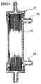
- Fig. 4 is a cross sectional diagram of a dialyzer showing the structure of a dialyzer provided in the piping of the dialysis apparatus.
- Fig. 5 is a structural outline diagram of a dialysis apparatus showing the structure and composition of a second embodiment of a dialysis apparatus.
- Fig. 6 is a structural outline diagram of a dialysis apparatus showing the structure and composition of a third embodiment of a dialysis apparatus.
- reference numeral 21 indicates an improved dialysis apparatus.
- This dialysis apparatus 21 has the following structure.
- a blood pump 24 is connected to a first pipe 23 which is coupled with the blood inlet 22 of a patient.
- An arterial-side chamber 26 is connected to this blood pump 24 through the medium of a second pipe 25.
- a dialyzer 28 is connected to the arterial-side chamber 26 through the medium of a third pipe 27.
- a venous-side chamber 30 is connected to dialyzer 28 through the medium of a fourth pipe 29.
- Venous-side chamber 30 is connected to a blood outlet 32 through the medium of a fifth pipe 31.
- First through fifth pipes 23 through 31 comprise the main piping.
- a supplementary fluid reservoir (supplementary fluid supply mechanism) 34 is connected to the first pipe 23 through the medium of a branch pipe 33.
- a first clamp 42 which opens and closes the first pipe 23, is provided on first pipe 23 at a position which is on the blood inlet 22 side of the branch point P at which the branch pipe 33 is connected, and a second clamp 43, which opens and closes the fifth pipe 31, is provided on the fifth pipe 31.
- a third clamp 44 which opens and closes the branch pipe 33, is provided on the branch pipe 33.
- control apparatus (control mechanism) 45 is connected to blood pump 24, first clamp 42, second clamp 43, and third clamp 44; by means of this control apparatus 45, the blood flow rate and blood flow direction of blood pump 24, and the open and closed state of first clamp 42, second clamp 43, and third clamp 44, are controlled.
- gas bubble detectors 46 and 46 are provided on first pipe 23 and fifth pipe 31 in the vicinity of blood inlet 22 and blood outlet 32, respectively, and these gas bubble detectors 46 and 46 are connected to control apparatus 45.
- Arterial-side chamber 26 and venous-side chamber 30 are formed of, for example, vinyl chloride, or the like, so that they possess a certain amount of elasticity.
- blood pump 24 When the dialysis of blood is to be conducted by means of dialysis apparatus 21, blood pump 24 is engaged, and the blood from the body of the patient is caused to circulate into the piping of the dialysis apparatus 21 in the direction shown by arrow A in Fig. 2. When this is done, this blood is passed through hollow capillary tubes (not depicted in the diagram) disposed within dialyzer 28, and waste products and the like which are present in the blood are removed.
- the amount of blood on the venous side that is to say, the amount of blood present in the piping from the branch point P to the blood outlet 32, is known in advance, so that when this amount of blood on the venous side has been returned to the veins, completion of the process is achieved.
- a hole is opened in supplementary fluid reservoir 34 and blood return is conducted by drawing air into the piping on the venous side after drawing supplementary fluid into this piping.
- gas bubble detector 46 detects the gas bubble in the vicinity of the blood outlet 32, and a signal is sent to control apparatus 45. Then, control apparatus 45 places the second clamp 43 in a closed state based on this signal, and thereby the entry of a gas bubble into the body of the patient can be prevented.
- the blood in the piping of the dialysis apparatus 21 can be reliably and easily returned to the body of the patient after the completion of blood dialysis.
- replenishment of body fluids by means of supplementary fluids after dialysis can also be accurately conducted by the appropriate setting of the operational conditions of control apparatus 45.
- the flow of the blood remaining within the dialyzer 28, when blood is returned to the venous-side in the improved dialysis apparatus, is improved.
- dialyzer 28 has a structure such that a plurality of hollow capillary tubes 52, 52, ... having an inner diameter of 30-1000 ⁇ m are disposed within the dialyzer and along the direction of blood flow; blood flows within these hollow capillary tubes 52, 52, ... .
- Reference numeral 53 indicates a flow opening permitting the circulation of dialysis fluid within the vessels of dialyzer 28.
- the blood remaining within the hollow capillary tubes 52, 52, ... of the dialyzer 28 cannot be caused to completely flow out merely by the passage of supplementary fluid by means of the blood pump 24.
- the first embodiment of the dialysis apparatus 51 is capable of causing the blood remaining within the dialyzer 28 to flow out, by comprising the following structure.
- this dialysis apparatus 51 is provided with a fourth clamp 55 on fourth pipe 29, which clamp is capable of opening and closing fourth pipe 29.
- This fourth clamp 55 is controlled by control apparatus 45 so as to open and close during the operation (4) of the improved dialysis apparatus above, in which blood is returned to the venous-side.
- the predetermined time period of the closed state of the fourth clamp 55 is set so that the flow rate of the blood or supplementary fluid sent from the blood pump 24 and stored in the arterial-side chamber 26 is less than the capacity of arterial-side chamber 26.
- a portion of fourth pipe 29 is parallel to fifth pipe 31, and these parallel pipes 29 and 31 are capable of simultaneous opening and closing by means of second clamp 43.
- second clamp 43 is used in a manner identical to that explained in the case of the improved dialysis apparatus above; during blood return operations of blood present within the piping from branch point P to blood outlet 32, this second clamp 43 is used in a manner identical to that of the fourth clamp 55 in the first embodiment.
- the functions of the fourth clamp 55 are provided by means of the second clamp 43, so that a simplification of the structure of the apparatus can be achieved.
- the supplementary fluid reservoir 34 normally has a small capacity, so that in the case in which the supplementary fluid within supplementary fluid reservoir 34 is exhausted, it is necessary to manually open a hole in supplementary fluid reservoir 34 and allow the entry of air into branch pipe 33, and the hole-opening operation in supplementary fluid reservoir 34 requires some labor.
- a control pipe 72 is connected to the branch pipe 33, and a fifth clamp 73, which is normally in a closed state, is provided at the end of this control pipe 72. Furthermore, a pressure sensor 74 is provided along branch pipe 33, and the detection data of this pressure sensor 74 are outputted to control apparatus 45. Based on the output data from this pressure sensor 74, control apparatus 45 conducts the opening and closing of fifth clamp 73.
- control apparatus 45 places fifth clamp 73 in a open state based on the detection data from pressure sensor 74, air enters branch pipe 33 automatically through the medium of control pipe 72, and by means of this, the blood return operation of the blood present in the piping from branch point P to blood outlet 32 can be conducted in a successful manner.
- the positions at which gas bubble detectors 46 and 46, first clamp 42, and second clamp 43 are disposed is not particularly restricted.
- gas bubble detectors 46 and 46 detect a gas bubble
- piping can be closed extremely rapidly by means of first clamp 42 and second clamp 43, so that no problems will occur even if these gas bubble detectors 46 and 46 are disposed at points on the side of the patient.
Landscapes
- Health & Medical Sciences (AREA)
- Heart & Thoracic Surgery (AREA)
- Vascular Medicine (AREA)
- Engineering & Computer Science (AREA)
- Anesthesiology (AREA)
- Biomedical Technology (AREA)
- Hematology (AREA)
- Life Sciences & Earth Sciences (AREA)
- Animal Behavior & Ethology (AREA)
- General Health & Medical Sciences (AREA)
- Public Health (AREA)
- Veterinary Medicine (AREA)
- Cardiology (AREA)
- External Artificial Organs (AREA)
Claims (11)
- Appareil de dialyse comprenant :une tuyauterie principale pour raccorder une entrée de sang (22) et une sortie de sang (32), une pompe à sang (24) disposée dans cette tuyauterie principale, un dialyseur (28) et une chambre côté veineux (30), prévus dans cet ordre depuis le côté d'entrée de sang ; etun mécanisme d'alimentation en fluide supplémentaire (34), raccordé entre ladite entrée de sang (22) et ladite pompe à sang (24) à ladite tuyauterie principale au moyen d'un tuyau de dérivation (33), dans lequel :
ladite pompe à sang (24) peut tourner dans les deux directions, vers l'avant et en sens inverse,
ledit appareil étant caractérisé en ce qu'il comprend en outre :un premier clamp (42) prévu entre ladite entrée de sang (22) de ladite tuyauterie principale et un point de branchement (P) pour ouvrir et fermer ladite tuyauterie principale, ledit tuyau de dérivation (33) étant raccordé au niveau dudit point de branchement (P) ;un deuxième clamp (43) prévu entre ledit dialyseur (28) et ladite sortie de sang (32) pour ouvrir et fermer ladite tuyauterie principale ;un troisième clamp (44) prévu sur ledit tuyau de dérivation (33) pour ouvrir et fermer ledit tuyau de dérivation (33) ; etun quatrième clamp (55) prévu entre ledit dialyseur (28) et ladite chambre côté veineux (30) de ladite tuyauterie principale. - Appareil de dialyse selon la revendication 1, dans lequel une chambre côté artériel (26) est prévue entre ladite pompe à sang (24) et ledit dialyseur (28).
- Appareil de dialyse selon la revendication 1, dans lequel il est prévu un moyen de détection de bulles de gaz (46) pour détecter des bulles de gaz dans le voisinage de ladite sortie de sang (43).
- Appareil de dialyse selon la revendication 1, dans lequel il est prévu un moyen de détection de bulles de gaz (46) pour détecter des bulles de gaz dans le voisinage de ladite entrée de sang (22).
- Appareil de dialyse selon la revendication 1, dans lequel il est prévu des moyens de détection de bulles de gaz (46) pour détecter les bulles de gaz dans les voisinages de ladite sortie de sang (32) et de ladite entrée de sang (22).
- Appareil de dialyse selon l'une des revendications 3 à 5, dans lequel, lorsqu'une bulle de gaz est détectée par lesdits moyens de détection de bulles de gaz (46), ledit premier clamp (42) et ledit deuxième clamp (43) sont placés dans des états fermés.
- Appareil de dialyse selon la revendication 1, dans lequel il est prévu un appareil de commande (45) qui commande le fonctionnement de ladite pompe à sang (24) et l'ouverture et la fermeture dudit premier clamp (42), dudit deuxième clamp (43), dudit troisième clamp (44) et dudit quatrième clamp (55).
- Appareil de dialyse selon la revendication 2, dans lequel une section de ladite tuyauterie principale entre ledit dialyseur (28) et ladite chambre côté veineux (30) et une section entre ladite chambre côté veineux (30) et ladite sortie de sang (32) sont parallèles, etces deux sections sont ouvertes et fermées au niveau de cette position parallèle au moyen dudit deuxième clamp (43).
- Appareil de dialyse selon la revendication 1, dans lequel il est prévu une ouverture d'admission d'air ayant un cinquième clamp (73) sur ledit mécanisme d'alimentation en fluide supplémentaire (34) et un capteur de pression (74) est prévu sur ledit tuyau de dérivation (33).
- Appareil de dialyse selon la revendication 9 dans lequel ledit cinquième clamp (73) de ladite ouverture d'admission d'air est commandé de façon à s'ouvrir et se fermer sur la base de données de sortie dudit capteur de pression (74).
- Procédé de mise en oeuvre d'un appareil de dialyse, dans lequel, après la fin d'une dialyse au moyen dudit appareil de dialyse comprenant :une tuyauterie principale qui est raccordée à une entrée de sang (22) et à une sortie de sang (32), et sur laquelle sont disposés, dans cet ordre depuis l'entrée de sang, une pompe à sang (24), une chambre côté artériel (26), un dialyseur (28) et une chambre côté veineux (30), ladite pompe à sang (24) pouvant tourner à la fois vers l'avant et en sens inverseun mécanisme d'alimentation en fluide supplémentaire (34), prévu sur un tuyau de dérivation (33) raccordé à ladite tuyauterie principale entre ladite entrée de sang (22) et ladite pompe à sang (24) ;un premier clamp (42) prévu entre ladite entrée de sang (22) de ladite tuyauterie principale et un point de branchement (P) pour ouvrir et fermer ladite tuyauterie principale, ledit tuyau de dérivation (33) étant raccordé au niveau dudit point de branchement (P) ;un deuxième clamp (43) prévu entre ledit dialyseur (28) et ladite sortie de sang (32) pour ouvrir et fermer ladite tuyauterie principale ;un troisième clamp (44) prévu sur ledit tuyau de dérivation (33) pour ouvrir et fermer ledit tuyau de dérivation (33) ; etun quatrième clamp (55) prévu entre ledit dialyseur (28) et ladite chambre côté veineux (30) de ladite tuyauterie principale ;
ledit procédé de mise en oeuvre étant caractérisé en ce qu'il comprend :une première étape comprenant :un processus d'aspiration dans lequel, dans un état dans lequel ledit premier clamp (42) est fermé et le deuxième clamp (43) est fermé,ladite pompe à sang (24) tourne dans le sens de rotation normal, etdu fluide supplémentaire est aspiré dans ladite tuyauterie principale en provenance dudit tuyau de dérivation (33), etun processus d'envoi dans lequel, dans un état dans lequel ledit troisième clamp (44) est fermé et ledit premier clamp (42) est ouvert,ladite pompe à sang (24) tourne dans le sens de rotation opposé, etdu fluide supplémentaire ainsi aspiré est envoyé à ladite entrée de sang (22), lesdits processus d'aspiration et de poussée étant répétés, etune deuxième étape dans laquelle ledit premier clamp (42) est fermé et ledit deuxième clamp (43) est ouvert,ladite pompe à sang (24) tourne dans le sens de rotation normal et du fluide supplémentaire est aspiré dudit tuyau de dérivation (33) dans la tuyauterie depuis ledit point de branchement (P) jusqu'à ladite sortie de sang (32), etdans lequel, pendant que ledit quatrième clamp (55) est fermé,une quantité de fluide supplémentaire inférieure à la capacité de ladite chambre côté artériel (26) est aspirée, etensuite ledit quatrième clamp (55) est ouvert,dans lequel lesdits processus d'ouverture et de fermeture dudit quatrième clamp (55) sont conduits de façon répétitive.
Applications Claiming Priority (4)
| Application Number | Priority Date | Filing Date | Title |
|---|---|---|---|
| JP18014492 | 1992-07-07 | ||
| JP180144/92 | 1992-07-07 | ||
| JP149635/93 | 1993-06-21 | ||
| JP5149635A JPH06261938A (ja) | 1992-07-07 | 1993-06-21 | 透析装置及び返血方法 |
Publications (2)
| Publication Number | Publication Date |
|---|---|
| EP0578175A1 EP0578175A1 (fr) | 1994-01-12 |
| EP0578175B1 true EP0578175B1 (fr) | 1998-10-07 |
Family
ID=26479468
Family Applications (1)
| Application Number | Title | Priority Date | Filing Date |
|---|---|---|---|
| EP93110728A Expired - Lifetime EP0578175B1 (fr) | 1992-07-07 | 1993-07-05 | Appareil de dialyse |
Country Status (4)
| Country | Link |
|---|---|
| US (1) | US5529685A (fr) |
| EP (1) | EP0578175B1 (fr) |
| JP (1) | JPH06261938A (fr) |
| DE (1) | DE69321403T2 (fr) |
Cited By (4)
| Publication number | Priority date | Publication date | Assignee | Title |
|---|---|---|---|---|
| DE10245619A1 (de) * | 2002-09-11 | 2004-03-25 | Fresenius Medical Care Deutschland Gmbh | Verfahren zur Blutrückgabe aus einer Blutbehandlungsvorrichtung und Vorrichtung zur Durchführung des Verfahrens |
| US7393337B2 (en) | 2002-02-22 | 2008-07-01 | Gambro Lundia Ab | Method of monitoring the operationality of a flow cut-off member and flow arresting system, for an extracorporeal fluid circuit |
| US7488301B2 (en) | 2002-09-11 | 2009-02-10 | Fresenius Medical Care Deutschland Gmbh | Method for returning blood from a blood treatment device, and device for carrying out this method |
| US9211370B2 (en) | 2003-12-16 | 2015-12-15 | Baxter International Inc. | Renal therapy blood cleansing system with isolation feature |
Families Citing this family (33)
| Publication number | Priority date | Publication date | Assignee | Title |
|---|---|---|---|---|
| US5591344A (en) * | 1995-02-13 | 1997-01-07 | Aksys, Ltd. | Hot water disinfection of dialysis machines, including the extracorporeal circuit thereof |
| DE19528907C1 (de) * | 1995-08-05 | 1996-11-07 | Fresenius Ag | Vorrichtung zur Ermittlung hämodynamischer Parameter während einer extrakorporalen Blutbehandlung |
| WO2001097878A1 (fr) | 2000-06-20 | 2001-12-27 | Intellicardia, Inc. | Appareil et procede de separation de circulation |
| US6572576B2 (en) † | 2001-07-07 | 2003-06-03 | Nxstage Medical, Inc. | Method and apparatus for leak detection in a fluid line |
| US7351218B2 (en) * | 2002-12-20 | 2008-04-01 | Gambro Lundia Ab | Device and process for extracorporeal treatment by citrate anticoagulant |
| FR2848857B1 (fr) * | 2002-12-20 | 2005-09-16 | Gambro Lundia Ab | Dispositif et ligne a usage unique pour le traitement extracorporel du sang par anticoagulation au citrate |
| ITMO20030293A1 (it) | 2003-10-29 | 2005-04-30 | Gambro Lundia Ab | Dispositivo per la determinazione del flusso di sangue in un circuito extracorporeo, nonche' apparecchiatura per il trattamento di sangue utilizzante lo stesso dispositivo. |
| JP4655596B2 (ja) * | 2003-11-21 | 2011-03-23 | 株式会社ジェイ・エム・エス | 自動返血装置 |
| US20060089586A1 (en) * | 2004-10-22 | 2006-04-27 | Kaus Stanley B | Convertible extracorporeal blood perfusion systems |
| US8834399B2 (en) | 2010-12-07 | 2014-09-16 | Zoll Lifebridge Gmbh | Cardiopulmonary apparatus and methods for preserving organ viability |
| US7713226B2 (en) * | 2006-01-06 | 2010-05-11 | Renal Solutions, Inc. | On demand and post-treatment delivery of saline to a dialysis patient |
| DE102006012087B4 (de) * | 2006-03-14 | 2008-10-02 | Fresenius Medical Care Deutschland Gmbh | Verfahren zum zumindest teilweise Entleeren eines extrakorporalen Blutkreislaufs und Hämodialysegerät zur Anwendung des Verfahrens |
| DE102006042120B3 (de) | 2006-09-07 | 2008-04-03 | Fresenius Medical Care Deutschland Gmbh | Blutbehandlungsgerät und Verfahren zum Entleeren eines Blutschlauchsatzes eines Blutbehandlungsgerätes |
| US8512553B2 (en) | 2007-07-05 | 2013-08-20 | Baxter International Inc. | Extracorporeal dialysis ready peritoneal dialysis machine |
| JP5311801B2 (ja) * | 2007-11-09 | 2013-10-09 | キヤノン株式会社 | 浸透圧ポンプを用いた送液駆動機構および該送液駆動機構を有するマイクロチップ |
| JP5205036B2 (ja) * | 2007-11-29 | 2013-06-05 | 日機装株式会社 | 血液浄化装置 |
| DE102009017304A1 (de) * | 2009-04-11 | 2010-10-21 | Fresenius Medical Care Deutschland Gmbh | Vorrichtung und Verfahren zur Messung eines Blutbestandteils im Blut für eine extrakorporale Blutbehandlungsvorrichtung |
| JP5426269B2 (ja) * | 2009-08-04 | 2014-02-26 | 日機装株式会社 | 血液回路及びそれを具備した血液浄化装置 |
| JP5514606B2 (ja) * | 2010-03-29 | 2014-06-04 | 旭化成メディカル株式会社 | 持続式血液濾過透析装置 |
| CN103619374B (zh) | 2010-12-07 | 2017-07-11 | 措尔生命桥梁有限责任公司 | 使过滤器逐步注满的用于体外血液治疗的装置的填充和排气的方法及系统 |
| JP5698010B2 (ja) * | 2011-01-24 | 2015-04-08 | 旭化成メディカル株式会社 | 血液浄化装置及び血液浄化装置の作動方法 |
| DE102011108777A1 (de) | 2011-07-29 | 2013-01-31 | Fresenius Medical Care Deutschland Gmbh | Verfahren zum Entfernen von Blut aus einem extrakorporalen Blutkreislauf sowie Vorrichtungen |
| JP5220171B2 (ja) * | 2011-08-17 | 2013-06-26 | 日機装株式会社 | 血液浄化装置 |
| JP5247864B2 (ja) * | 2011-08-31 | 2013-07-24 | 日機装株式会社 | 血液浄化装置 |
| JP2013048803A (ja) * | 2011-08-31 | 2013-03-14 | Nikkiso Co Ltd | 血液浄化装置 |
| JP5934581B2 (ja) * | 2012-06-04 | 2016-06-15 | 東レ・メディカル株式会社 | 血液浄化装置 |
| GB2503032B (en) * | 2012-06-15 | 2014-05-28 | Univ United Arab Emirates | Serviceable bioreactor |
| JP5968101B2 (ja) * | 2012-06-15 | 2016-08-10 | 旭化成メディカル株式会社 | 血液浄化装置の回路内の液体を減らす方法、血液浄化装置及びプログラム |
| JP2013106976A (ja) * | 2013-03-05 | 2013-06-06 | Nikkiso Co Ltd | 血液浄化装置 |
| US9440017B2 (en) | 2013-03-14 | 2016-09-13 | Baxter International Inc. | System and method for performing alternative and sequential blood and peritoneal dialysis modalities |
| US9498567B2 (en) | 2014-09-29 | 2016-11-22 | Fenwal, Inc. | Systems and methods for controlling the return phase of a blood separation procedure |
| US9486590B2 (en) | 2014-09-29 | 2016-11-08 | Fenwal, Inc. | Automatic purging of air from a fluid processing system |
| EP3505200B1 (fr) * | 2017-12-29 | 2020-09-09 | Gambro Lundia AB | Appareil pour traitement sanguin extracorporel |
Family Cites Families (13)
| Publication number | Priority date | Publication date | Assignee | Title |
|---|---|---|---|---|
| US3946731A (en) * | 1971-01-20 | 1976-03-30 | Lichtenstein Eric Stefan | Apparatus for extracorporeal treatment of blood |
| IE40006B1 (en) * | 1973-09-07 | 1979-02-14 | Lichtenstein Eric Stefan | Automated apparatus for monitoring of physiological parameters and control of fluid therapy including extracorporealcirculation of blood |
| US4191182A (en) * | 1977-09-23 | 1980-03-04 | Hemotherapy Inc. | Method and apparatus for continuous plasmaphersis |
| IL64001A0 (en) * | 1981-10-06 | 1982-01-31 | Elmar Medical Systems Ltd | Blood treatment system |
| EP0118473A4 (fr) * | 1982-08-24 | 1985-09-16 | Baxter Travenol Lab | Systemes et procedes de recuperation de composants du sang a rendement accru. |
| DE3313421C2 (de) * | 1983-04-13 | 1985-08-08 | Fresenius AG, 6380 Bad Homburg | Einrichtung zum Regeln der Ultrafiltrationsrate bei Vorrichtungen zum extrakorporalen Reinigen von Blut |
| DE3335744C1 (de) * | 1983-10-01 | 1984-12-13 | B. Braun Melsungen Ag, 3508 Melsungen | Dialysevorrichtung |
| US4661246A (en) * | 1984-10-01 | 1987-04-28 | Ash Medical Systems, Inc. | Dialysis instrument with dialysate side pump for moving body fluids |
| US4596549A (en) * | 1984-12-27 | 1986-06-24 | Nihon Medical Engineering Company, Ltd. | Blood dialyzing method and apparatus |
| BE905615R (nl) * | 1986-09-10 | 1987-04-17 | Hombrouckx Remi O J | Methode en apparatuur voor eennaaldhemodialyse. |
| DE3720664A1 (de) * | 1987-06-23 | 1989-01-05 | Schael Wilfried | Vorrichtung zur behandlung von blut durch dialyse und/oder filtration |
| AU6041190A (en) * | 1989-06-20 | 1991-01-08 | University Of Washington | Combined hemofiltration and hemodialysis system |
| US5227049A (en) * | 1990-08-20 | 1993-07-13 | Hospal Industrie | Single-needle circuit for circulating blood outside the body in blood treatment apparatus |
-
1993
- 1993-06-21 JP JP5149635A patent/JPH06261938A/ja active Pending
- 1993-07-02 US US08/087,389 patent/US5529685A/en not_active Expired - Lifetime
- 1993-07-05 EP EP93110728A patent/EP0578175B1/fr not_active Expired - Lifetime
- 1993-07-05 DE DE69321403T patent/DE69321403T2/de not_active Expired - Lifetime
Cited By (6)
| Publication number | Priority date | Publication date | Assignee | Title |
|---|---|---|---|---|
| US7393337B2 (en) | 2002-02-22 | 2008-07-01 | Gambro Lundia Ab | Method of monitoring the operationality of a flow cut-off member and flow arresting system, for an extracorporeal fluid circuit |
| US7935072B2 (en) | 2002-02-22 | 2011-05-03 | Gambro Lundia Ab | Method of monitoring the operationality of a flow cut-off member and flow arresting system, for an extracorporeal fluid circuit |
| DE10245619A1 (de) * | 2002-09-11 | 2004-03-25 | Fresenius Medical Care Deutschland Gmbh | Verfahren zur Blutrückgabe aus einer Blutbehandlungsvorrichtung und Vorrichtung zur Durchführung des Verfahrens |
| DE10245619B4 (de) * | 2002-09-11 | 2004-08-26 | Fresenius Medical Care Deutschland Gmbh | Verfahren zur Blutrückgabe aus einer Blutbehandlungsvorrichtung und Vorrichtung zur Durchführung des Verfahrens |
| US7488301B2 (en) | 2002-09-11 | 2009-02-10 | Fresenius Medical Care Deutschland Gmbh | Method for returning blood from a blood treatment device, and device for carrying out this method |
| US9211370B2 (en) | 2003-12-16 | 2015-12-15 | Baxter International Inc. | Renal therapy blood cleansing system with isolation feature |
Also Published As
| Publication number | Publication date |
|---|---|
| DE69321403T2 (de) | 1999-03-04 |
| JPH06261938A (ja) | 1994-09-20 |
| DE69321403D1 (de) | 1998-11-12 |
| EP0578175A1 (fr) | 1994-01-12 |
| US5529685A (en) | 1996-06-25 |
Similar Documents
| Publication | Publication Date | Title |
|---|---|---|
| EP0578175B1 (fr) | Appareil de dialyse | |
| AU2017206273B2 (en) | External functional device, blood treatment apparatus for accommodating such an external functional device, and methods | |
| US3946731A (en) | Apparatus for extracorporeal treatment of blood | |
| CN100363066C (zh) | 在体液体外处理中用于体液流动控制的装置和方法 | |
| JP4267917B2 (ja) | ダイアフィルトレーションモジュール | |
| EP1952832B1 (fr) | Appareil de purification du sang pour examiner l'etat de raccordement d'aiguilles de ponction | |
| KR101076352B1 (ko) | 혈액의 체외 처리용 회로 및 그 내부에서 사용된 유동 전환장치 | |
| CN101784291B (zh) | 血液净化装置 | |
| JP2000107284A (ja) | 透析装置および洗浄プライミング方法 | |
| WO2012017959A1 (fr) | Dispositif d'épuration du sang, et procédé pour l'inspection de fuite de liquide dans un tel dispositif | |
| JP2000107283A (ja) | 透析装置および洗浄プライミング方法 | |
| JP2001514938A5 (fr) | ||
| JPS6096262A (ja) | 透析装置 | |
| EP2571546B1 (fr) | Interface utilisateur et machine | |
| US4721564A (en) | Apparatus for the filtration of plasma from blood | |
| US20040084371A1 (en) | Dialysis system and method for automatically priming a dialyzer | |
| EP2797643B1 (fr) | Appareil de traitement sanguin extracorporel | |
| US11690942B2 (en) | Blood purification apparatus with a bypass line that bypasses an ultrafiltration pump | |
| US5893382A (en) | Method and device for flushing a membrane apparatus | |
| JP5431228B2 (ja) | 血液浄化装置 | |
| EP3603697B1 (fr) | Dispositif de purification de sang | |
| US20210030938A1 (en) | A blood hose set, a control device or closed-loop control device, a blood treatment apparatus and a method for the single-needle treatment | |
| US20080208101A1 (en) | Diversion Of Emboli During Fluid Circulation | |
| US20210077703A1 (en) | Blood Purification Apparatus and Method of Acquiring Plasma Flow Rate On Blood Purification Apparatus | |
| JPH0221872A (ja) | 血漿分離装置およびその制御方法 |
Legal Events
| Date | Code | Title | Description |
|---|---|---|---|
| PUAI | Public reference made under article 153(3) epc to a published international application that has entered the european phase |
Free format text: ORIGINAL CODE: 0009012 |
|
| AK | Designated contracting states |
Kind code of ref document: A1 Designated state(s): DE FR GB IT |
|
| 17P | Request for examination filed |
Effective date: 19940314 |
|
| 17Q | First examination report despatched |
Effective date: 19950614 |
|
| GRAG | Despatch of communication of intention to grant |
Free format text: ORIGINAL CODE: EPIDOS AGRA |
|
| GRAG | Despatch of communication of intention to grant |
Free format text: ORIGINAL CODE: EPIDOS AGRA |
|
| GRAG | Despatch of communication of intention to grant |
Free format text: ORIGINAL CODE: EPIDOS AGRA |
|
| GRAH | Despatch of communication of intention to grant a patent |
Free format text: ORIGINAL CODE: EPIDOS IGRA |
|
| GRAH | Despatch of communication of intention to grant a patent |
Free format text: ORIGINAL CODE: EPIDOS IGRA |
|
| ITF | It: translation for a ep patent filed |
Owner name: UFFICIO TECNICO ING. A. MANNUCCI |
|
| GRAA | (expected) grant |
Free format text: ORIGINAL CODE: 0009210 |
|
| AK | Designated contracting states |
Kind code of ref document: B1 Designated state(s): DE FR GB IT |
|
| REF | Corresponds to: |
Ref document number: 69321403 Country of ref document: DE Date of ref document: 19981112 |
|
| ET | Fr: translation filed | ||
| PLBE | No opposition filed within time limit |
Free format text: ORIGINAL CODE: 0009261 |
|
| STAA | Information on the status of an ep patent application or granted ep patent |
Free format text: STATUS: NO OPPOSITION FILED WITHIN TIME LIMIT |
|
| 26N | No opposition filed | ||
| REG | Reference to a national code |
Ref country code: GB Ref legal event code: IF02 |
|
| REG | Reference to a national code |
Ref country code: GB Ref legal event code: 732E |
|
| REG | Reference to a national code |
Ref country code: FR Ref legal event code: TQ |
|
| PGFP | Annual fee paid to national office [announced via postgrant information from national office to epo] |
Ref country code: GB Payment date: 20120723 Year of fee payment: 20 |
|
| PGFP | Annual fee paid to national office [announced via postgrant information from national office to epo] |
Ref country code: DE Payment date: 20120921 Year of fee payment: 20 Ref country code: FR Payment date: 20120803 Year of fee payment: 20 Ref country code: IT Payment date: 20120726 Year of fee payment: 20 |
|
| REG | Reference to a national code |
Ref country code: DE Ref legal event code: R071 Ref document number: 69321403 Country of ref document: DE |
|
| REG | Reference to a national code |
Ref country code: DE Ref legal event code: R071 Ref document number: 69321403 Country of ref document: DE |
|
| REG | Reference to a national code |
Ref country code: GB Ref legal event code: PE20 Expiry date: 20130704 |
|
| PG25 | Lapsed in a contracting state [announced via postgrant information from national office to epo] |
Ref country code: DE Free format text: LAPSE BECAUSE OF EXPIRATION OF PROTECTION Effective date: 20130706 |
|
| PG25 | Lapsed in a contracting state [announced via postgrant information from national office to epo] |
Ref country code: GB Free format text: LAPSE BECAUSE OF EXPIRATION OF PROTECTION Effective date: 20130704 |