EP0577149A1 - Verfahren zur Reinigung von Abgasen - Google Patents
Verfahren zur Reinigung von Abgasen Download PDFInfo
- Publication number
- EP0577149A1 EP0577149A1 EP19930111993 EP93111993A EP0577149A1 EP 0577149 A1 EP0577149 A1 EP 0577149A1 EP 19930111993 EP19930111993 EP 19930111993 EP 93111993 A EP93111993 A EP 93111993A EP 0577149 A1 EP0577149 A1 EP 0577149A1
- Authority
- EP
- European Patent Office
- Prior art keywords
- activated carbon
- gas
- electrostatic precipitator
- waste gas
- wet electrostatic
- Prior art date
- Legal status (The legal status is an assumption and is not a legal conclusion. Google has not performed a legal analysis and makes no representation as to the accuracy of the status listed.)
- Withdrawn
Links
Images

Classifications
-
- F—MECHANICAL ENGINEERING; LIGHTING; HEATING; WEAPONS; BLASTING
- F01—MACHINES OR ENGINES IN GENERAL; ENGINE PLANTS IN GENERAL; STEAM ENGINES
- F01N—GAS-FLOW SILENCERS OR EXHAUST APPARATUS FOR MACHINES OR ENGINES IN GENERAL; GAS-FLOW SILENCERS OR EXHAUST APPARATUS FOR INTERNAL COMBUSTION ENGINES
- F01N3/00—Exhaust or silencing apparatus having means for purifying, rendering innocuous, or otherwise treating exhaust
- F01N3/08—Exhaust or silencing apparatus having means for purifying, rendering innocuous, or otherwise treating exhaust for rendering innocuous
-
- B—PERFORMING OPERATIONS; TRANSPORTING
- B01—PHYSICAL OR CHEMICAL PROCESSES OR APPARATUS IN GENERAL
- B01D—SEPARATION
- B01D53/00—Separation of gases or vapours; Recovering vapours of volatile solvents from gases; Chemical or biological purification of waste gases, e.g. engine exhaust gases, smoke, fumes, flue gases, aerosols
- B01D53/007—Separation of gases or vapours; Recovering vapours of volatile solvents from gases; Chemical or biological purification of waste gases, e.g. engine exhaust gases, smoke, fumes, flue gases, aerosols by irradiation
-
- B—PERFORMING OPERATIONS; TRANSPORTING
- B01—PHYSICAL OR CHEMICAL PROCESSES OR APPARATUS IN GENERAL
- B01D—SEPARATION
- B01D53/00—Separation of gases or vapours; Recovering vapours of volatile solvents from gases; Chemical or biological purification of waste gases, e.g. engine exhaust gases, smoke, fumes, flue gases, aerosols
- B01D53/34—Chemical or biological purification of waste gases
- B01D53/46—Removing components of defined structure
- B01D53/54—Nitrogen compounds
- B01D53/56—Nitrogen oxides
-
- B—PERFORMING OPERATIONS; TRANSPORTING
- B01—PHYSICAL OR CHEMICAL PROCESSES OR APPARATUS IN GENERAL
- B01D—SEPARATION
- B01D53/00—Separation of gases or vapours; Recovering vapours of volatile solvents from gases; Chemical or biological purification of waste gases, e.g. engine exhaust gases, smoke, fumes, flue gases, aerosols
- B01D53/34—Chemical or biological purification of waste gases
- B01D53/46—Removing components of defined structure
- B01D53/60—Simultaneously removing sulfur oxides and nitrogen oxides
-
- B—PERFORMING OPERATIONS; TRANSPORTING
- B03—SEPARATION OF SOLID MATERIALS USING LIQUIDS OR USING PNEUMATIC TABLES OR JIGS; MAGNETIC OR ELECTROSTATIC SEPARATION OF SOLID MATERIALS FROM SOLID MATERIALS OR FLUIDS; SEPARATION BY HIGH-VOLTAGE ELECTRIC FIELDS
- B03C—MAGNETIC OR ELECTROSTATIC SEPARATION OF SOLID MATERIALS FROM SOLID MATERIALS OR FLUIDS; SEPARATION BY HIGH-VOLTAGE ELECTRIC FIELDS
- B03C3/00—Separating dispersed particles from gases or vapour, e.g. air, by electrostatic effect
- B03C3/01—Pretreatment of the gases prior to electrostatic precipitation
- B03C3/013—Conditioning by chemical additives, e.g. with SO3
-
- B—PERFORMING OPERATIONS; TRANSPORTING
- B03—SEPARATION OF SOLID MATERIALS USING LIQUIDS OR USING PNEUMATIC TABLES OR JIGS; MAGNETIC OR ELECTROSTATIC SEPARATION OF SOLID MATERIALS FROM SOLID MATERIALS OR FLUIDS; SEPARATION BY HIGH-VOLTAGE ELECTRIC FIELDS
- B03C—MAGNETIC OR ELECTROSTATIC SEPARATION OF SOLID MATERIALS FROM SOLID MATERIALS OR FLUIDS; SEPARATION BY HIGH-VOLTAGE ELECTRIC FIELDS
- B03C3/00—Separating dispersed particles from gases or vapour, e.g. air, by electrostatic effect
- B03C3/019—Post-treatment of gases
-
- B—PERFORMING OPERATIONS; TRANSPORTING
- B03—SEPARATION OF SOLID MATERIALS USING LIQUIDS OR USING PNEUMATIC TABLES OR JIGS; MAGNETIC OR ELECTROSTATIC SEPARATION OF SOLID MATERIALS FROM SOLID MATERIALS OR FLUIDS; SEPARATION BY HIGH-VOLTAGE ELECTRIC FIELDS
- B03C—MAGNETIC OR ELECTROSTATIC SEPARATION OF SOLID MATERIALS FROM SOLID MATERIALS OR FLUIDS; SEPARATION BY HIGH-VOLTAGE ELECTRIC FIELDS
- B03C3/00—Separating dispersed particles from gases or vapour, e.g. air, by electrostatic effect
- B03C3/02—Plant or installations having external electricity supply
- B03C3/16—Plant or installations having external electricity supply wet type
-
- B—PERFORMING OPERATIONS; TRANSPORTING
- B03—SEPARATION OF SOLID MATERIALS USING LIQUIDS OR USING PNEUMATIC TABLES OR JIGS; MAGNETIC OR ELECTROSTATIC SEPARATION OF SOLID MATERIALS FROM SOLID MATERIALS OR FLUIDS; SEPARATION BY HIGH-VOLTAGE ELECTRIC FIELDS
- B03C—MAGNETIC OR ELECTROSTATIC SEPARATION OF SOLID MATERIALS FROM SOLID MATERIALS OR FLUIDS; SEPARATION BY HIGH-VOLTAGE ELECTRIC FIELDS
- B03C3/00—Separating dispersed particles from gases or vapour, e.g. air, by electrostatic effect
- B03C3/34—Constructional details or accessories or operation thereof
- B03C3/38—Particle charging or ionising stations, e.g. using electric discharge, radioactive radiation or flames
- B03C3/383—Particle charging or ionising stations, e.g. using electric discharge, radioactive radiation or flames using radiation
-
- F—MECHANICAL ENGINEERING; LIGHTING; HEATING; WEAPONS; BLASTING
- F01—MACHINES OR ENGINES IN GENERAL; ENGINE PLANTS IN GENERAL; STEAM ENGINES
- F01N—GAS-FLOW SILENCERS OR EXHAUST APPARATUS FOR MACHINES OR ENGINES IN GENERAL; GAS-FLOW SILENCERS OR EXHAUST APPARATUS FOR INTERNAL COMBUSTION ENGINES
- F01N13/00—Exhaust or silencing apparatus characterised by constructional features ; Exhaust or silencing apparatus, or parts thereof, having pertinent characteristics not provided for in, or of interest apart from, groups F01N1/00 - F01N5/00, F01N9/00, F01N11/00
- F01N13/009—Exhaust or silencing apparatus characterised by constructional features ; Exhaust or silencing apparatus, or parts thereof, having pertinent characteristics not provided for in, or of interest apart from, groups F01N1/00 - F01N5/00, F01N9/00, F01N11/00 having two or more separate purifying devices arranged in series
-
- F—MECHANICAL ENGINEERING; LIGHTING; HEATING; WEAPONS; BLASTING
- F01—MACHINES OR ENGINES IN GENERAL; ENGINE PLANTS IN GENERAL; STEAM ENGINES
- F01N—GAS-FLOW SILENCERS OR EXHAUST APPARATUS FOR MACHINES OR ENGINES IN GENERAL; GAS-FLOW SILENCERS OR EXHAUST APPARATUS FOR INTERNAL COMBUSTION ENGINES
- F01N3/00—Exhaust or silencing apparatus having means for purifying, rendering innocuous, or otherwise treating exhaust
- F01N3/01—Exhaust or silencing apparatus having means for purifying, rendering innocuous, or otherwise treating exhaust by means of electric or electrostatic separators
-
- F—MECHANICAL ENGINEERING; LIGHTING; HEATING; WEAPONS; BLASTING
- F01—MACHINES OR ENGINES IN GENERAL; ENGINE PLANTS IN GENERAL; STEAM ENGINES
- F01N—GAS-FLOW SILENCERS OR EXHAUST APPARATUS FOR MACHINES OR ENGINES IN GENERAL; GAS-FLOW SILENCERS OR EXHAUST APPARATUS FOR INTERNAL COMBUSTION ENGINES
- F01N3/00—Exhaust or silencing apparatus having means for purifying, rendering innocuous, or otherwise treating exhaust
- F01N3/08—Exhaust or silencing apparatus having means for purifying, rendering innocuous, or otherwise treating exhaust for rendering innocuous
- F01N3/0892—Electric or magnetic treatment, e.g. dissociation of noxious components
-
- F—MECHANICAL ENGINEERING; LIGHTING; HEATING; WEAPONS; BLASTING
- F01—MACHINES OR ENGINES IN GENERAL; ENGINE PLANTS IN GENERAL; STEAM ENGINES
- F01N—GAS-FLOW SILENCERS OR EXHAUST APPARATUS FOR MACHINES OR ENGINES IN GENERAL; GAS-FLOW SILENCERS OR EXHAUST APPARATUS FOR INTERNAL COMBUSTION ENGINES
- F01N2250/00—Combinations of different methods of purification
-
- F—MECHANICAL ENGINEERING; LIGHTING; HEATING; WEAPONS; BLASTING
- F01—MACHINES OR ENGINES IN GENERAL; ENGINE PLANTS IN GENERAL; STEAM ENGINES
- F01N—GAS-FLOW SILENCERS OR EXHAUST APPARATUS FOR MACHINES OR ENGINES IN GENERAL; GAS-FLOW SILENCERS OR EXHAUST APPARATUS FOR INTERNAL COMBUSTION ENGINES
- F01N2370/00—Selection of materials for exhaust purification
- F01N2370/40—Activated carbon or charcoal
-
- Y—GENERAL TAGGING OF NEW TECHNOLOGICAL DEVELOPMENTS; GENERAL TAGGING OF CROSS-SECTIONAL TECHNOLOGIES SPANNING OVER SEVERAL SECTIONS OF THE IPC; TECHNICAL SUBJECTS COVERED BY FORMER USPC CROSS-REFERENCE ART COLLECTIONS [XRACs] AND DIGESTS
- Y02—TECHNOLOGIES OR APPLICATIONS FOR MITIGATION OR ADAPTATION AGAINST CLIMATE CHANGE
- Y02A—TECHNOLOGIES FOR ADAPTATION TO CLIMATE CHANGE
- Y02A50/00—TECHNOLOGIES FOR ADAPTATION TO CLIMATE CHANGE in human health protection, e.g. against extreme weather
- Y02A50/20—Air quality improvement or preservation, e.g. vehicle emission control or emission reduction by using catalytic converters
-
- Y—GENERAL TAGGING OF NEW TECHNOLOGICAL DEVELOPMENTS; GENERAL TAGGING OF CROSS-SECTIONAL TECHNOLOGIES SPANNING OVER SEVERAL SECTIONS OF THE IPC; TECHNICAL SUBJECTS COVERED BY FORMER USPC CROSS-REFERENCE ART COLLECTIONS [XRACs] AND DIGESTS
- Y02—TECHNOLOGIES OR APPLICATIONS FOR MITIGATION OR ADAPTATION AGAINST CLIMATE CHANGE
- Y02T—CLIMATE CHANGE MITIGATION TECHNOLOGIES RELATED TO TRANSPORTATION
- Y02T10/00—Road transport of goods or passengers
- Y02T10/10—Internal combustion engine [ICE] based vehicles
- Y02T10/12—Improving ICE efficiencies
Definitions
- This invention relates to a method of purifying waste gases, more particularly, to a method of purifying waste gases that are contaminated by automotive exhaust gases and other emissions and which contain nitrogen oxides (nitrogen monoxide and nitrogen dioxide), a carbon-containing powder and low concentration of sulfur oxides.
- nitrogen oxides nitrogen monoxide and nitrogen dioxide
- the method of reducing nitrogen oxides to nitrogen gas using catalysts is not suitable for the purpose of removing nitrogen oxides from gases at ordinary temperatures since the effects of the catalysts used are not exhibited unless the reaction temperature is at least 300°C.
- Exposure to ultraviolet radiation causes nitrogen oxides to decompose into N2 and O2 in the presence of added ammonia, with the attendant capability of converting nitrogen oxides to ammonium nitrate.
- this method has a slow reaction rate and hence is not suitable for application to flowing gases.
- Exposure to ultraviolet radiation may be combined with an adsorption process in such a way that the ozone produced by exposure to ultraviolet radiation is reacted with nitrogen monoxide to form nitrogen dioxide, which is adsorbed on an adsorbent.
- the adsorbents available today have such a low capacity for removing nitrogen dioxide that they have to be replaced fairly often and this makes said combined process uneconomical.
- the absorption process is a kind of wet process that employs various chemical absorbents to absorb target materials by chemical reactions.
- no effective chemicals have been found to date that react with nitrogen monoxide at ordinary temperatures and the absorbents available today are inadequate for gases having a high NO content which are contaminated by automotive exhaust gases and other emissions.
- the adsorption process uses adsorbents to remove nitrogen oxides (chiefly nitrogen dioxide) in either a physical or chemical way. This is the most common method used today to purify air that contains nitrogen dioxide at low concentrations. However, this method cannot be considered to be effective in treating gases of the kind to be treated by the present invention which contain certain levels of nitrogen oxides (chiefly nitrogen monoxide). Stated more specifically, the concentration of nitrogen dioxide in the air atmosphere is usually no more than several tens of ppb (parts per billion), which is less than the concentration of nitrogen dioxide in the gases under consideration by several tens of times.
- the adsorption method is effective for treating gases with very low concentrations of nitrogen dioxide but the adsorbents available today have a short effective life and are unable to withstand prolonged use in the treatment of gases that contain at least 50% more nitrogen monoxide than conventionally treated gases and which contain nitrogen monoxide at concentrations in the order of several ppm.
- the results of tests conducted by the assignee showed that even alkali-loaded carbon which has the highest capacity for removing nitrogen dioxide of all the absorbents known today including zeolite and activated carbon, showed a 50% or more deterioration in its adsorbent capability to in less than several tens of hours at a linear velocity (LV) of 0.5 m/sec.
- LV linear velocity
- the capacity of adsorbents must be maintained for at least one month and the cost for maintaining their capacity is also an important factor to be considered in selecting an effective method of removing nitrogen oxides.
- Exposure to electron beams is a technique developed by the assignee; in this process, highly reactive radicals such as O, OH and HO2 are generated by exposure to electron beams so that SOx and NOx are converted to sulfuric acid and nitric acid, respectively, which react with added ammonia and are recovered as ammonium sulfate and ammonium nitrate.
- highly reactive radicals such as O, OH and HO2 are generated by exposure to electron beams so that SOx and NOx are converted to sulfuric acid and nitric acid, respectively, which react with added ammonia and are recovered as ammonium sulfate and ammonium nitrate.
- exhaust gas containing SO2 and NOx is introduced into a reactor where it is exposed to electron beam radiation with a dose rate of 0.5 - 1.0 Mrad/sec.
- the exhaust gas is then supplied into an electrical dust precipitator.
- an electrical dust precipitator To achieve a mixture or double salt of ammonium sulfate/nitrate a limited amount of ammonia is added to the exhaust gas before or after radiation treatment.
- EP-A-0 294 658 discloses a process for treating an effluent gas containing sulfur oxides and/or nitrogen oxides wherein the effluent gas is irradiated by ionizing irradiation, ammonia is added to the effluent gas before, during or after the irradiation and the resulting ammonium sulfate and/or ammonium nitrate are collected by means of a dry dust collector.
- Exposure to electron beams can also be used as a method for treating gases that are contaminated by automotive exhaust gases and other emissions and which contain nitrogen monoxide and nitrogen dioxide.
- a method for treating gases that are contaminated by automotive exhaust gases and other emissions and which contain nitrogen monoxide and nitrogen dioxide is disclosed in JP-A-63 291 626.
- this method comprises exposing a waste gas to electron beams in the absence of ammonia and subsequently treating it with either an activated carbon based adsorbent or a zeolite based adsorbent.
- the adsorbents used have a rather low capacity for removing nitrate ions or nitrogen dioxide and must be replaced fairly often which constitutes a significant economic problem.
- An object, therefore, of the present invention is to provide a method of purification by which deleterious materials can be removed in an efficient, economical and safe manner from waste gases that are contaminated by automotive exhaust gases and other emissions and which contain nitrogen oxides (NOx), a carbon-containing powder and low concentration of sulfur oxides.
- NOx nitrogen oxides
- the above-stated object of the present invention can be attained by a method which comprises adding ammonia to a waste gas containing deleterious materials originating from automotive exhaust gases and other emissions, exposing said waste gas to an ionizing radiation, and subsequently passing the gas through a wet electrostatic precipitator.
- the method of the present invention is intended to purify a waste gas that contains nitrogen oxides, a carbon-containing powder and sulfur oxides that originate from automotive exhaust gases and other emissions, and it is characterized by adding ammonia to said gas, exposing it to an ionizing radiation, and removing the resulting dust and/or mist and carbon with a wet electrostatic precipitator, whereby the nitrogen oxides and carbon-containing powder in the gas are removed.
- this method of purifying the waste gas may include an additional step in which the gas is passed through a layer of an activated carbon based filler after the treatment with the wet electrostatic precipitator.
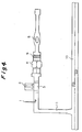
- Figs. 1 and 2 are flow diagrams showing the sequence of steps involved in implementing the method of the present invention in accordance with preferred examples;
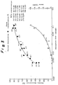
- Fig. 3 is a graph showing the relationship between absorption dose and each of the percent denitration and ozone concentration; and
- Fig. 4 illustrates the concept of the method of the present invention as it is applied to a tunnel for automobiles.
- reaction scheme 1 When a gas such as air is exposed to an ionizing radiation, the components of the gas, i.e., nitrogen, oxygen and water, generate highly reactive radicals such as N, O, OH and HO2 (reaction scheme 1): These radicals react with the nitrogen oxides to be removed and nitrogen gas and nitric acid will be generated according to the following reaction schemes 2 - 4: NO + N ⁇ N2 + 1/2 O2 (scheme 2) NO + HO2 ⁇ HNO3 (scheme 3) NO2 + OH ⁇ HNO3 (scheme 4)
- the nitrogen gas generated in accordance with reaction scheme 2 is released as a harmless gas, whereas the nitric acid generated in accordance with reaction scheme 3 or 4 turns to ammonium nitrate in the presence of ammonia according to the following reaction scheme 5: HNO3 + NH3 ⁇ NH4NO3 (scheme 5)
- the reactions according to schemes 1 - 5 are completed momentarily within one second.
- ammonium nitrate and ammonium sulfate obtained by the reactions described above are recovered with a wet electrostatic precipitator.
- ammonium sulfate is usually present and recovered together with ammonium nitrate.
- Unburnt carbon also is usually present in a smaller amount than ammonium nitrate.
- An exemplary wet method of recovery is the use of a scrubber but if the amount of air to be treated is very large as in the case to which the present invention is applied, increased pressure loss will occur. This problem, combined with the possibility of mist leakage, makes the scrubber process unsuitable for the purposes of the present invention.
- the method of recovering by-products with a wet electrostatic precipitator is recommended in that the ammonium nitrate based by-product which results from the treatment of automotive exhaust gases and other emissions by exposure to an ionizing radiation can be recovered in a safe way without causing the problems of pressure loss and mist leakage.
- a wet electrostatic precipitator has the advantage of reducing the amount of leaking ammonia since any ammonia that remains unreacted can be absorbed not only by the spray water used but also by the action of the wetted wall.
- a further advantage is improved cost efficiency since if the water used in the wet electrostatic precipitator is circulated and used repeatedly, the concentration of ammonium nitrate being recovered can be sufficiently increased so that it can be utilized as a fertilizer.
- an activated carbon based filler may be used at the final stage of the apparatus combining exposure to an ionizing radiation with a wet electrostatic precipitator and this insures that the ozone generated by exposure to an ionizing radiation or by electrification with the precipitator is decomposed.
- the activated carbon based filler is not intended to remove NOx.
- the activated carbon based filler is capable of decomposing more ozone than its own weight and, hence, the use of the activated carbon based filler for the purpose of ozone decomposition is reasonably economical. For increasing the efficiency of removal of nitrogen oxides, it is effective to increase the exposure dose of ionizing radiation.
- the activated carbon based filler is a fibrous, particulate or agglomerate material that contains activated carbon. These materials will insure that the gas treated by exposure to an ionizing radiation and with the wet electrostatic precipitator come in contact with reduced pressure loss at a linear velocity (LV) of ca. 0.01 - 1.0 m/sec.
- Particulate activated carbon is desirably mixed with zeolite or silica gel since not only the potential risk of burning which may occur when concentrated ozone is decomposed with activated carbon alone is eliminated but also its ability to decompose ozone is improved. It is also possible to use "loaded carbon" which has a chemical such as an alkali metal carbonate added to activated carbon.
- the activated carbon based filler that can be used in the present invention may be selected from among any type of activated carbon that is commonly used as an adsorbent.
- the activated carbon based filler has marginal effectiveness in removing nitrogen monoxide and its ability to remove nitrogen dioxide is also very low (in the order of a few ppm) and will deteriorate very rapidly in no more than several tens of hours. Thus, when it is used for the purpose of removing nitrogen dioxide, it must be replaced fairly often and this makes its use uneconomical as already pointed out in connection with the description of the prior art. However, it has been confirmed that besides the ability to decompose ozone, the activated carbon based filler is also capable of reducing deleterious nitrogen dioxide to less toxic nitrogen monoxide.
- any dust particles collected on the surfaces of the activated carbon based filler particles can be dislodged to ensure the whole surface is utilized. This also facilitates replacement of an exhausted activated carbon based filler with a fresh filler.
- Examples of the ionizing radiation that may be applied to the gases of the type to which the present invention is applied and which contain nitrogen oxides include electron beams, ⁇ -rays, ⁇ -rays, ⁇ -rays, X-rays and neutron beams; electron beams may be conveniently used.
- the dose of such ionizing radiation within the range of 0.001 Mrad - 0.5 Mrad will generally suffice for the purposes of the present invention.
- These ionizing radiations may be applied at ordinary temperatures.
- the voltage to be applied to the wet electrostatic precipitator is preferably within the range of ca. 10 - 100 kV.
- nitrogen oxide compounds having lower oxidation state in the gas being treated reacts with radicals such as N, O, OH and HO2 resulting from the nitrogen, oxygen and water in the gas upon exposure to an ionizing radiation, whereby it is converted to harmless nitrogen gas or oxidized to a compound having a higher oxidation state (nitric acid), which will react with ammonia to form ammonium nitrate.
- nitric acid a compound having a higher oxidation state
- the resulting ammonium nitrate is recovered in a safe form into the circulating water in the wet electrostatic precipitator.
- any deleterious ozone generated is decomposed with the activated carbon based filler loaded in the last stage of the process.
- the activated carbon based filler offers an additional advantage in that the nitrogen dioxide that remains after the treatments described above is reduced to nitrogen monoxide which has comparatively low toxicity.
- the gases to be treated by the method of the present invention are those which contain nitrogen oxides in amounts in the order of a few ppm, and the method will prove particularly effective when it is applied to purification of waste gases that originate from automotive exhaust gases, such as those which occur in tunnels for automobiles or in parking lots in the basement of buildings.
- the exhaust gases occurring in such tunnels are known to contain ca. 0.1 - 5.0 ppm of NOx, ca. 0.05 - 1.0 mg/m3 of soot and dust particles, solid carbon (ca. 10 - 80% of the soot/dust content) and trace amounts of SO2.
- Fig. 4 shows the concept of the method of the present invention as it is applied to a tunnel for automobiles. Shown by 10 in Fig. 4 is the tunnel and 11 is an exhaust duct, the air from which is treated by the method of the present invention.
- Fig. 1 is a flow diagram showing the sequence of steps involved in implementing the method of the present invention in accordance with a preferred example.
- numeral 1 denotes the area where ammonia is added; 2 is an apparatus for applying an ionizing radiation; 3 is a reactor; 4 is a wet electrostatic precipitator; and 5 is a blower. After being mixed with ammonia in area 1, the gas to be treated enters the reactor 3, where it is exposed to an ionizing radiation and thence supplied to the wet electrostatic precipitator 4.
- Air containing 1.8 - 2.7 ppm of NOx (80 - 90% NO, with the remainder being NO2), ca. 0.1 - 0.7 mg/m3 of soot and dust particles (50% solid carbon in the soot and dust) and trace amounts of SO2 was fed into the reactor 3 at ambient temperature and at a rate of 1.000 Nm3/h, in which reactor the air was exposed to electron beams from the electron beam generator 2 for a total dose of 0.004 Mrad - 0.12 Mrad. Before exposure to electron beams, the gas was mixed with ammonia that was added in area 1 in an amount that corresponded to 0.65 - 1.1 equivalents compared to the concentration of NOx.
- the concentration of NOx in the gas was measured with a chemiluminescent NOx meter and the results are shown in Fig. 3 as percent denitration, or the percentage of removed NOx with reference to the concentration of NOx at the inlet to the reactor.
- the graph of Fig. 3 shows the relationship between absorption dose and each of the percent denitration ( ⁇ NOx) and ozone concentration. Most of the NOx in the outlet gas was detected in the form of nitrogen dioxide.
- the percent denitration improved with the increase in absorption dose and, at a dose in the region of 0.05 Mrad, the percent denitration was at least 80%. Even when the dose was in the region of 0.005 Mrad, about 50% denitration was achieved.
- the percent denitration ( ⁇ NOx) differed with the concentration of NOx and the general tendency was such that the lower the NOx concentration, the higher the ⁇ NOx.
- ⁇ NOx was 31%, 37% and 47% when the NOx concentration was 2.70 ppm (c), 2.30 ppm (b) and 2.05 ppm (a), respectively.
- the dose of exposure for the waste gas to be treated will vary with the concentration of NOx at the inlet and the percent denitration required of the waste gas.
- the range of concentrations of NOx in the gas to be treated by the present invention (ca.
- the ozone concentration was also measured; it increased as the absorption dose increased and upon exposure for a dose in the region of 0.05 Mrad, the measured concentration of ozone was 2.0 ppm. However, at an exposure dose in the region of 0.005 Mrad, the ozone concentration was less than 0.1 ppm.
- Fig. 2 is a flow diagram illustrating another example of the present invention. The process shown in Fig. 2 is the same as that of Fig. 1 except that it provides an activated carbon based filler layer 9 subsequent to the wet electrostatic precipitator 4.
- Example 2 Using the process shown in Fig. 2, a test was conducted as in Example 1, with electron beams being mainly applied for an absorption dose that ranged from about 0.05 Mrad to about 0.1 Mrad.
- the filler layer 9 was packed with crushed particles of activated carbon and part of the gas exposed to electron beams was introduced into the filler layer 30 mm thick at a linear velocity of 0.8 m/sec. Thereafter, the concentrations of NOx and ozone were measured as in Example 1.
- the crushed particles of activated carbon lost their denitrating ability and the concentration of NOx in the outlet gas was substantially equal to the value attained in Example 1 but at least 60% of the NOx detected was nitrogen monoxide. No ozone was detected at all in the gas that had passed through the layer of crushed particles of activated carbon.
- the present invention was capable of efficient removal of low concentration of NOx present at concentrations of the ppm order.
- the method of the present invention offers the following advantages.
Landscapes
- Engineering & Computer Science (AREA)
- Chemical & Material Sciences (AREA)
- Combustion & Propulsion (AREA)
- Mechanical Engineering (AREA)
- General Engineering & Computer Science (AREA)
- Health & Medical Sciences (AREA)
- Chemical Kinetics & Catalysis (AREA)
- General Chemical & Material Sciences (AREA)
- Analytical Chemistry (AREA)
- Oil, Petroleum & Natural Gas (AREA)
- Toxicology (AREA)
- Environmental & Geological Engineering (AREA)
- Biomedical Technology (AREA)
- General Health & Medical Sciences (AREA)
- Treating Waste Gases (AREA)
- Transition And Organic Metals Composition Catalysts For Addition Polymerization (AREA)
- Filtering Of Dispersed Particles In Gases (AREA)
- Electrostatic Separation (AREA)
Applications Claiming Priority (2)
| Application Number | Priority Date | Filing Date | Title |
|---|---|---|---|
| JP2674589 | 1989-02-07 | ||
| JP26745/89 | 1989-02-07 |
Related Parent Applications (2)
| Application Number | Title | Priority Date | Filing Date |
|---|---|---|---|
| EP90902843A Division-Into EP0408772B1 (de) | 1989-02-07 | 1990-02-07 | Reinigungsverfahren für auspuffgase |
| EP90902843.3 Division | 1990-02-07 |
Publications (1)
| Publication Number | Publication Date |
|---|---|
| EP0577149A1 true EP0577149A1 (de) | 1994-01-05 |
Family
ID=12201838
Family Applications (2)
| Application Number | Title | Priority Date | Filing Date |
|---|---|---|---|
| EP90902843A Expired - Lifetime EP0408772B1 (de) | 1989-02-07 | 1990-02-07 | Reinigungsverfahren für auspuffgase |
| EP19930111993 Withdrawn EP0577149A1 (de) | 1989-02-07 | 1990-02-07 | Verfahren zur Reinigung von Abgasen |
Family Applications Before (1)
| Application Number | Title | Priority Date | Filing Date |
|---|---|---|---|
| EP90902843A Expired - Lifetime EP0408772B1 (de) | 1989-02-07 | 1990-02-07 | Reinigungsverfahren für auspuffgase |
Country Status (4)
| Country | Link |
|---|---|
| EP (2) | EP0408772B1 (de) |
| AT (1) | ATE106768T1 (de) |
| DE (1) | DE69009605T2 (de) |
| WO (1) | WO1990009227A1 (de) |
Cited By (3)
| Publication number | Priority date | Publication date | Assignee | Title |
|---|---|---|---|---|
| WO1996004066A1 (de) * | 1994-07-29 | 1996-02-15 | Christoph Dyckerhoff | Vorrichtung zur behandlung von abgasen |
| WO1996024805A1 (en) * | 1995-02-08 | 1996-08-15 | James Winchester | Process and device for destroying hazardous compounds in incinerator flue gas |
| EP1542792A2 (de) * | 2002-08-30 | 2005-06-22 | Washington University in St. Louis | Laden und einfangen von partikeln in mit in-situ-röntgenstrahlen bestrahlten koronas |
Families Citing this family (14)
| Publication number | Priority date | Publication date | Assignee | Title |
|---|---|---|---|---|
| US5029535A (en) * | 1990-05-14 | 1991-07-09 | Wahlco, Inc. | Control of addition of conditioning agents to flue gas |
| US5087428A (en) * | 1990-05-30 | 1992-02-11 | Systemes Ozonics Inc. | Air purifying system |
| DE4115369A1 (de) * | 1991-03-28 | 1992-10-01 | Asea Brown Boveri | Verfahren zur minimierung der stickstoffoxyde (nox) bei einer verbrennung |
| JPH0671134A (ja) * | 1992-07-09 | 1994-03-15 | Toshiba Corp | 排ガス中の二酸化炭素除去装置および二酸化炭素除去方法 |
| DE4233303C1 (de) * | 1992-10-03 | 1994-01-20 | Metallgesellschaft Ag | Verfahren zur Abtrennung von Dioxinen und Furanen aus Abgasen von Verbrennungsanlagen |
| JP3725196B2 (ja) * | 1995-03-01 | 2005-12-07 | 日本エンバイロケミカルズ株式会社 | 窒素含有分子篩活性炭、その製造方法及び用途 |
| US5695616A (en) * | 1995-09-27 | 1997-12-09 | Virginia Accelerators Corporation | Electron beam flue gas scrubbing treatment |
| DE10243488A1 (de) * | 2002-09-19 | 2004-04-01 | Hjs Fahrzeugtechnik Gmbh & Co. | Verfahren zum Entfernen von Rußpartikeln aus dem Abgasstrom einer Brennkraftmaschine sowie passive Abgasreinigungseinrichtung |
| JP2007029819A (ja) * | 2005-07-25 | 2007-02-08 | Kawasaki Heavy Ind Ltd | 排ガス浄化電子線照射装置 |
| US9981056B2 (en) | 2015-02-27 | 2018-05-29 | Mazra Incorporated | Air treatment system |
| DE102016223556B4 (de) | 2015-12-09 | 2023-09-28 | Ford Global Technologies, Llc | Kraftfahrzeug mit Staubsensor und Verfahren zur Minderung von Staubaufwirbelung durch ein Kraftfahrzeug |
| CN106950158A (zh) | 2015-12-09 | 2017-07-14 | 福特全球技术公司 | 具有粉尘传感器的机动车辆和用于减少机动车辆的粉尘再悬浮或粉尘排放的方法 |
| CN106422704B (zh) * | 2016-11-04 | 2022-10-14 | 浙江大学 | 多种污染物一体化深度脱除系统 |
| CN112263903A (zh) * | 2020-09-25 | 2021-01-26 | 唐山中润煤化工有限公司 | 一种化工污水的恶臭气体收集处理系统 |
Citations (5)
| Publication number | Priority date | Publication date | Assignee | Title |
|---|---|---|---|---|
| FR2113283A5 (de) * | 1970-10-26 | 1972-06-23 | Mahoning Associates Inc | |
| EP0268094A2 (de) * | 1986-10-22 | 1988-05-25 | KRC Umwelttechnik GmbH | Verfahren und Vorrichtung zur Reinigung von Rauchgasen |
| EP0269060A2 (de) * | 1986-11-26 | 1988-06-01 | Ebara Corporation | Verfahren zur Behandlung eines Nebenproduktes bei der Bestrahlung eines Abgases, dem Ammoniak zugesetzt wurde |
| EP0294658A1 (de) * | 1987-05-30 | 1988-12-14 | Ebara Corporation | Verfahren zur Behandlung von Abgasen |
| EP0326686A1 (de) * | 1987-12-10 | 1989-08-09 | Ebara Corporation | Verfahren zur Behandlung von Abgas durch Bestrahlung mit Elektronenstrahlen |
Family Cites Families (3)
| Publication number | Priority date | Publication date | Assignee | Title |
|---|---|---|---|---|
| JPS51151258A (en) * | 1975-06-20 | 1976-12-25 | Hitachi Ltd | An exhaust gas purification apparatus |
| JPS52140499A (en) * | 1976-05-19 | 1977-11-24 | Ebara Corp | Production of mixture or double salt of ammonium sulfate/nitrate by radiation treatment of exhaust gas |
| JPS63291626A (ja) * | 1987-05-22 | 1988-11-29 | Ebara Corp | 窒素酸化物を含有するガスから窒素酸化物を除去する方法 |
-
1990
- 1990-02-07 WO PCT/JP1990/000150 patent/WO1990009227A1/ja active IP Right Grant
- 1990-02-07 EP EP90902843A patent/EP0408772B1/de not_active Expired - Lifetime
- 1990-02-07 DE DE69009605T patent/DE69009605T2/de not_active Expired - Fee Related
- 1990-02-07 AT AT90902843T patent/ATE106768T1/de not_active IP Right Cessation
- 1990-02-07 EP EP19930111993 patent/EP0577149A1/de not_active Withdrawn
Patent Citations (5)
| Publication number | Priority date | Publication date | Assignee | Title |
|---|---|---|---|---|
| FR2113283A5 (de) * | 1970-10-26 | 1972-06-23 | Mahoning Associates Inc | |
| EP0268094A2 (de) * | 1986-10-22 | 1988-05-25 | KRC Umwelttechnik GmbH | Verfahren und Vorrichtung zur Reinigung von Rauchgasen |
| EP0269060A2 (de) * | 1986-11-26 | 1988-06-01 | Ebara Corporation | Verfahren zur Behandlung eines Nebenproduktes bei der Bestrahlung eines Abgases, dem Ammoniak zugesetzt wurde |
| EP0294658A1 (de) * | 1987-05-30 | 1988-12-14 | Ebara Corporation | Verfahren zur Behandlung von Abgasen |
| EP0326686A1 (de) * | 1987-12-10 | 1989-08-09 | Ebara Corporation | Verfahren zur Behandlung von Abgas durch Bestrahlung mit Elektronenstrahlen |
Cited By (4)
| Publication number | Priority date | Publication date | Assignee | Title |
|---|---|---|---|---|
| WO1996004066A1 (de) * | 1994-07-29 | 1996-02-15 | Christoph Dyckerhoff | Vorrichtung zur behandlung von abgasen |
| WO1996024805A1 (en) * | 1995-02-08 | 1996-08-15 | James Winchester | Process and device for destroying hazardous compounds in incinerator flue gas |
| EP1542792A2 (de) * | 2002-08-30 | 2005-06-22 | Washington University in St. Louis | Laden und einfangen von partikeln in mit in-situ-röntgenstrahlen bestrahlten koronas |
| EP1542792A4 (de) * | 2002-08-30 | 2007-09-12 | Univ St Louis | Laden und einfangen von partikeln in mit in-situ-röntgenstrahlen bestrahlten koronas |
Also Published As
| Publication number | Publication date |
|---|---|
| EP0408772A4 (en) | 1991-07-31 |
| DE69009605T2 (de) | 1994-09-22 |
| WO1990009227A1 (en) | 1990-08-23 |
| ATE106768T1 (de) | 1994-06-15 |
| EP0408772A1 (de) | 1991-01-23 |
| DE69009605D1 (de) | 1994-07-14 |
| EP0408772B1 (de) | 1994-06-08 |
Similar Documents
| Publication | Publication Date | Title |
|---|---|---|
| EP0408772B1 (de) | Reinigungsverfahren für auspuffgase | |
| US7048899B2 (en) | Removing NOx, SO2, and Hg from a gas stream using limestone regeneration | |
| CN102489149B (zh) | 废气净化处理方法 | |
| US7998445B2 (en) | Method and apparatus for the treatment of nitrogen oxides using an ozone and catalyst hybrid system | |
| EP0474263B1 (de) | Methode zum Modifizieren des Nebenproduktes eines Abgassbehandlungsprozesses | |
| US5607496A (en) | Removal of mercury from a combustion gas stream and apparatus | |
| US6761863B2 (en) | Process for the removal of impurities from gas streams | |
| CA2431460C (en) | Process for the removal of impurities from gas streams | |
| US8529852B2 (en) | Flue-gas purification and reclamation system and method thereof | |
| US4004995A (en) | Process for removing nitrogen oxides and sulfur dioxide from effluent gases | |
| JPH0616818B2 (ja) | 排ガス浄化方法及び装置 | |
| JPH0262297B2 (de) | ||
| Shin et al. | Removal of NOx using electron beam process with NaOH spraying | |
| JPS6359729B2 (de) | ||
| JP2007181757A (ja) | 排ガス中の水銀除去方法 | |
| JPS61133125A (ja) | 紫外線脱硝法 | |
| JP2003112010A (ja) | 脱臭装置 | |
| KR100255020B1 (ko) | 가열된 연소 기체로부터 이산화황 및 NOx 제거에 의해 유출되는 수용성 알카리 토류 질산화물 비료 조성물과 그 제조방법 | |
| KR19990071259A (ko) | 배가스 재활용방법 및 그 장치 | |
| JPS61111126A (ja) | 排ガスの処理方法 | |
| JPH07171346A (ja) | 亜酸化窒素の除去方法 | |
| JPH1057756A (ja) | 乾式排ガス処理方法 | |
| Chmielewski | Electron beams for power plant flue gas treatment | |
| JPS60251917A (ja) | 排煙脱硫脱硝方法 | |
| KR800001304B1 (ko) | 배(排) 가스중 질소산화물 및 이산화 유황을 제거하는 신규방법 |
Legal Events
| Date | Code | Title | Description |
|---|---|---|---|
| PUAI | Public reference made under article 153(3) epc to a published international application that has entered the european phase |
Free format text: ORIGINAL CODE: 0009012 |
|
| 17P | Request for examination filed |
Effective date: 19930816 |
|
| AC | Divisional application: reference to earlier application |
Ref document number: 408772 Country of ref document: EP |
|
| AK | Designated contracting states |
Kind code of ref document: A1 Designated state(s): AT CH DE FR GB IT LI |
|
| RIN1 | Information on inventor provided before grant (corrected) |
Inventor name: OKAMOTO, KYOICHI Inventor name: AGARIDA, TORU Inventor name: MAEZAWA AKIHIKO Inventor name: SUZUKI RYOJI Inventor name: AOKI SHINJI |
|
| 17Q | First examination report despatched |
Effective date: 19950707 |
|
| STAA | Information on the status of an ep patent application or granted ep patent |
Free format text: STATUS: THE APPLICATION IS DEEMED TO BE WITHDRAWN |
|
| 18D | Application deemed to be withdrawn |
Effective date: 19960118 |