EP0577099A2 - Cooling apparatus for electronic elements - Google Patents
Cooling apparatus for electronic elements Download PDFInfo
- Publication number
- EP0577099A2 EP0577099A2 EP93110438A EP93110438A EP0577099A2 EP 0577099 A2 EP0577099 A2 EP 0577099A2 EP 93110438 A EP93110438 A EP 93110438A EP 93110438 A EP93110438 A EP 93110438A EP 0577099 A2 EP0577099 A2 EP 0577099A2
- Authority
- EP
- European Patent Office
- Prior art keywords
- cooling
- cooling apparatus
- unit
- electronic element
- base member
- Prior art date
- Legal status (The legal status is an assumption and is not a legal conclusion. Google has not performed a legal analysis and makes no representation as to the accuracy of the status listed.)
- Granted
Links
Images


Classifications
-
- H—ELECTRICITY
- H01—ELECTRIC ELEMENTS
- H01L—SEMICONDUCTOR DEVICES NOT COVERED BY CLASS H10
- H01L23/00—Details of semiconductor or other solid state devices
- H01L23/34—Arrangements for cooling, heating, ventilating or temperature compensation ; Temperature sensing arrangements
-
- H—ELECTRICITY
- H01—ELECTRIC ELEMENTS
- H01L—SEMICONDUCTOR DEVICES NOT COVERED BY CLASS H10
- H01L23/00—Details of semiconductor or other solid state devices
- H01L23/34—Arrangements for cooling, heating, ventilating or temperature compensation ; Temperature sensing arrangements
- H01L23/42—Fillings or auxiliary members in containers or encapsulations selected or arranged to facilitate heating or cooling
- H01L23/427—Cooling by change of state, e.g. use of heat pipes
-
- F—MECHANICAL ENGINEERING; LIGHTING; HEATING; WEAPONS; BLASTING
- F28—HEAT EXCHANGE IN GENERAL
- F28D—HEAT-EXCHANGE APPARATUS, NOT PROVIDED FOR IN ANOTHER SUBCLASS, IN WHICH THE HEAT-EXCHANGE MEDIA DO NOT COME INTO DIRECT CONTACT
- F28D15/00—Heat-exchange apparatus with the intermediate heat-transfer medium in closed tubes passing into or through the conduit walls ; Heat-exchange apparatus employing intermediate heat-transfer medium or bodies
- F28D15/02—Heat-exchange apparatus with the intermediate heat-transfer medium in closed tubes passing into or through the conduit walls ; Heat-exchange apparatus employing intermediate heat-transfer medium or bodies in which the medium condenses and evaporates, e.g. heat pipes
- F28D15/0275—Arrangements for coupling heat-pipes together or with other structures, e.g. with base blocks; Heat pipe cores
-
- H—ELECTRICITY
- H01—ELECTRIC ELEMENTS
- H01L—SEMICONDUCTOR DEVICES NOT COVERED BY CLASS H10
- H01L25/00—Assemblies consisting of a plurality of individual semiconductor or other solid state devices ; Multistep manufacturing processes thereof
- H01L25/03—Assemblies consisting of a plurality of individual semiconductor or other solid state devices ; Multistep manufacturing processes thereof all the devices being of a type provided for in the same subgroup of groups H01L27/00 - H01L33/00, or in a single subclass of H10K, H10N, e.g. assemblies of rectifier diodes
- H01L25/04—Assemblies consisting of a plurality of individual semiconductor or other solid state devices ; Multistep manufacturing processes thereof all the devices being of a type provided for in the same subgroup of groups H01L27/00 - H01L33/00, or in a single subclass of H10K, H10N, e.g. assemblies of rectifier diodes the devices not having separate containers
- H01L25/07—Assemblies consisting of a plurality of individual semiconductor or other solid state devices ; Multistep manufacturing processes thereof all the devices being of a type provided for in the same subgroup of groups H01L27/00 - H01L33/00, or in a single subclass of H10K, H10N, e.g. assemblies of rectifier diodes the devices not having separate containers the devices being of a type provided for in group H01L29/00
- H01L25/072—Assemblies consisting of a plurality of individual semiconductor or other solid state devices ; Multistep manufacturing processes thereof all the devices being of a type provided for in the same subgroup of groups H01L27/00 - H01L33/00, or in a single subclass of H10K, H10N, e.g. assemblies of rectifier diodes the devices not having separate containers the devices being of a type provided for in group H01L29/00 the devices being arranged next to each other
-
- H—ELECTRICITY
- H05—ELECTRIC TECHNIQUES NOT OTHERWISE PROVIDED FOR
- H05K—PRINTED CIRCUITS; CASINGS OR CONSTRUCTIONAL DETAILS OF ELECTRIC APPARATUS; MANUFACTURE OF ASSEMBLAGES OF ELECTRICAL COMPONENTS
- H05K7/00—Constructional details common to different types of electric apparatus
- H05K7/20—Modifications to facilitate cooling, ventilating, or heating
- H05K7/2089—Modifications to facilitate cooling, ventilating, or heating for power electronics, e.g. for inverters for controlling motor
- H05K7/20936—Liquid coolant with phase change
-
- H—ELECTRICITY
- H01—ELECTRIC ELEMENTS
- H01L—SEMICONDUCTOR DEVICES NOT COVERED BY CLASS H10
- H01L2924/00—Indexing scheme for arrangements or methods for connecting or disconnecting semiconductor or solid-state bodies as covered by H01L24/00
- H01L2924/0001—Technical content checked by a classifier
- H01L2924/0002—Not covered by any one of groups H01L24/00, H01L24/00 and H01L2224/00
Definitions
- the present invention relates to a cooling apparatus for electronic elements, and more particularly, to a cooling apparatus which is suitable to cool semiconductor elements such as transistors and thyristers.
- the cooling apparatus disclosed in the latter publication comprises an electronic device, a metallic block which serves as a heatsink of the electronic device, a plurality of heat pipes each extending in the vertical direction with one end thereof inserted in the metallic block and having a plurality of horizontal cooling fins provided at the other end thereof, a thermal conductive electric insulator disposed between the electronic device and the metallic block, conductor metals formed integrally with the thermal conductive electric insulator or both surfaces thereof, a duct which envelops the cooling fins, and a fan to supply cold wind to the duct.
- the thermal conductive electric insulator having the conductor metals formed integrally therewith, the electronic device and the metallic block are kept in pressure contact with each other or bonded together by means of bonding agent.
- Heat of the electronic device is transferred to the metallic block through the conductor metal, the thermal conductive electric insulator and the other conductor metal. Heat transferred to the metallic block is transferred to a refrigerant sealingly contained in the heat pipes and it evaporates the refrigerant. The evaporated refrigerant moves upwards within the heat pipes to the other ends thereof where the radiation fins are provided. At the other ends, heat is removed by the cold wind supplied by the fan, so that the refrigerant is liquefied and returned to the one ends of the heat pipes. In this way, heat of the electronic device is dissipated into the air.
- the radiation fins extend in the horizontal direction, the air warmed by the radiation fins is hindered from moving upwards by the radiation fins themselves. For this reason, heat radiation by natural convection is not sufficient and, hence, the fan for the forced cooling is required.
- the heat pipes extend in the vertical direction, there is a problem that the heightwise length of the cooling apparatus is increased. Further, in case that the calorific value of the electronic device is large, it is necessary to increase the radiation capacities of the metallic block and the heat pipes. In this case, however, the widthwise length of the metallic block and the number of the heat pipes must be increased, resulting in a problem that the widthwise length of the cooling apparatus is increased.
- An object of the present invention is to provide a cooling apparatus for electronic deive which is capable of easily coping with change of the design of the electronic device at a low cost without deteriorating the thermal conductivity, achieving a good heat radiation by natural convection and achieving a high degree of freedom in changing the radiation capacity.
- a cooling apparatus for electronic device comprises an electronic element unit which comprises a base member, a thermal conductive electric insulating layer soldered to the base member and a plurality of electronic elements soldered to the thermal conductive electric insulating layer, at least one cooling unit which is detachably kept in pressure contact with the base member of the electronic element unit and comprises a cooling block, at least one heat pipe having a refrigerant sealingly contained therein and inserted in the cooling block at one end thereof in the vertical direction and a plurality of radiation fins provided at the other end of the at least one heat pipe substantially perpendicular to an axis of the heat pipe, and means for detachably keeping the electronic element unit and the cooling unit in pressure contact with each other.
- the other end of the heat pipe extends obliquely with a predetermined angle with respect to the inserted portion thereof.
- the predetermined angle is not greater than 90° and, particularly, not greater than 83°.
- the cooling block is made of ceramic or metal. Further, the refrigerant sealingly contained in the heat pipe is water.
- a plurality of cooling units are arranged in the vertical direction.
- thermal conductive grease is sandwiched between the base member of the electronic device unit and the cooling unit.
- at least one of the pressure contact surfaces of the base member and the cooling unit is formed therein with a plurality of microgrooves.
- the cooling unit may comprise a fan duct which extends in parallel with the radiation fins so as to envelop the same therein and a fan which is disposed in the fan duct so as to produce air currents directed toward the radiation fins.
- the cooling apparatus comprises the electronic element unit, the cooling unit and the means for detachably keeping these units in pressure contact with each other, when it becomes necessary to change the design of some electronic elements in the electronic element unit, it is possible to detach the electronic element unit, change the electronic elements and bring the electronic element unit and the cooling unit into pressure contact with each other again by the pressure contact means. Further, the positioning between the electronic element unit and the cooling unit can be performed automatically by the pressure contact means. Namely, the cooling apparatus according to the present invention has a good flexibility to change of the design of the electronic elements and is capable of changing the design at a low cost.
- the electronic elements are soldered to the thermal conductive electric insulating layer and the thermal conductive electric insulating layer is soldered to the base member, so that there is no possibility of generation of the contact thermal resistance between them.
- the portion where the contact thermal resistance is generated is only the pressure contact surface between the base member of the electronic element unit and the cooling block of the cooling unit. Therefore, heat of the electronic element unit can be transferred to the cooling unit satisfactorily, so that cooling of the electronic element unit can be performed sufficiently.
- the electronic elements and the base member are electrically isolated from each other in the electronic element unit, there is no possibility that the electric current flows through the cooling unit. Accordingly, the refrigerant to be sealingly contained in the heat pipe does not need to have an electric insulation. Therefore, it becomes possible to use water as the refrigerant of the heat pipe.
- the other end of the heat pipe where the radiation fins are provided extends obliquely with respect to the portion thereof which is inserted in the cooling block in the vertical direction, the radiation fins are made to extend substantially in the vertical direction. For this reason, the air warmed by the radiation fins is allowed to flow upwards through the radiation fins, resulting in that heat can be dissipated satisfactorily due to natural convection. Since heat radiation can be performed satisfactorily without equipping any fan, it is possible to improve the reliability of the cooling apparatus.
- the other end portion of the heat pipe where the radiation fins are provided extends obliquely with respect to the vertical direction, a plurality of cooling units can be arranged in multiple stages in the vertical direction. Accordingly, it is possible to change the cooling capacity of the cooling unit in accordance with the calorific value of the electronic device unit without increasing the widthwise length of the cooling apparatus.
- a cooling apparatus for electronic device 10 comprises an electronic element unit 11, a cooling unit 12 and bolts 13 by means of which these units are detachably kept in pressure contact with each other.
- the electronic element unit 11 has a base member 14 made of copper.
- a thermal conductive electric insulating layer 15 is soldered to one of the surfaces of the base member 14, and a plurality of electronic elements 16 including thyrister and transistor, for example, are soldered to the thermal conductive electric insulating layer 15.
- Resin 17 is molded around the electronic elements 16, and the surface of the molded resin 17 is reinforced by plastic 18. As occasion demands, the resin 17 and the reinforcing plastic 18 may be dispensed with.
- the cooling unit 12 has a cooling block 19 which is made of copper or ceramic and kept in contact with the other surface of the base member 14.
- the cooling block 19 is formed therein with a plurality of holes 20 extending in the vertical direction.
- a refrigerant e.g., water 22 is sealingly contained.
- the heat pipe 21 extends, at a position where it is projected out of the cooling block 19, obliquely so as to make a predetermined angle ⁇ of not greater than 90° with respect to the vertical line, and a plurality of radiation fins 23 are provided in the end portion of the heat pipe 21 so as to extend in the direction perpendicular to the axis of the heat pipe 21. In other words, the plurality of radiation fins 23 extend substantially in the vertical direction.
- the cooling block 19 is formed in position with through holes (not shown) which extend in the lateral direction, and the base member 14 is formed in position corresponding to these through holes with threaded holes (not shown).
- the bolts 13 are passed through the through holes and screwed in the threaded holes. By so doing, the base member 14 and the cooling block 19 are kept in pressure contact with each other.
- thermal conductive grease 24 may be sandwiched as shown in Figure 1.
- at least one of contact surfaces 26 and 25 of the base member 14 and the cooling block 19 is formed therein with grooves 27 or 28 which serve to receive the excessive thermal conductive grease 24.
- the contact surface of the base member 14 and the contact surface of the cooling block 19 are kept in pressure contact with each other and the excessive thermal conductive grease is received in the grooves 27, 28, and therefore, it is possible to form a thin film of thermal conductive grease, resulting in that the thermal conductivity can be improved.
- the electronic elements 16 are soldered to the thermal conductive electric insulating layer 15, there is no possibility of generation of the contact thermal resistance between them. Accordingly, heat generated by the electronic element 16 is transferred efficiently to the thermal conductive electric insulating layer 15. Since the thermal conductive electric insulating layer 15 is soldered to the base member 14, there is no possibility of generation of the contact thermal resistance between them as well. Accordingly, heat transferred to the thermal conductive electric insulating layer 15 is transmitted effectively to the base member 14. Heat transmitted to the base member 14 is transferred to the cooling block 19 so as to heat the refrigerant (water) in the heat pipe 21, resulting in that the refrigerant is evaporated. The evaporated refrigerant moves upwards within the heat pipe 21 to the other ends thereof where the radiation fins 23 are provided.
- the air warmed by the radiation fins 23 due to heat exchange between the radiation fins 23 and the ambient air moves upwards through the radiation fins 23 without being hindered thereby since the radiation fins extend substantially in the vertical direction, thereby causing natural convection to occur.
- the radiation fins can be supplied with cold air at all times so that heat dissipation from the radiation fins to the ambient air can be performed effectively.
- the refrigerant is liquefied and returned to the cooling block. In this way, heat of the electronic elements can be dissipated into the ambient air effectively.
- the cooling apparatus 10 comprises the electronic element unit 11, the cooling unit 12 and the means 13 for detachably keeping these units in pressure contact with each other, when it becomes necessary to change the design of the electronic elements 16 in the electronic element unit 11, it is possible to detach the electronic element unit 11, change the electronic elements 16 and bring the electronic element unit 11 and the cooling unit 12 into pressure contact with each other again by the pressure contact means 13. Further, the positioning between the electronic element unit 11 and the cooling unit 12 can be per-formed automatically by the pressure contact means 13. Namely, the cooling apparatus according to the present invention has a good flexibility to change of the design of the electronic elements and is capable of changing the design at a low cost.
- the electronic elements 16 are soldered to the thermal conductive electric insulating layer 15 and the thermal conductive electric insulating layer 15 is soldered to the base member 14, so that there is no possibility of generation of the contact thermal resistance between them.
- the portion where the contact thermal resistance is generated is only the pressure contact surface between the base member 14 of the electronic element unit 11 and the cooling block 19 of the cooling unit 12. Therefore, heat of the electronic element unit 11 can be transferred to the cooling unit 12 satisfactorily, so that cooling of the electronic element unit 11 can be performed sufficiently.
- the electronic elements 16 and the base member 14 are electrically isolated from each other in the electronic element unit 11, there is no possibility that the electric current flows through the cooling unit 12. Accordingly, the refrigerant 22 to be sealingly contained in the heat pipe 21 does not need to have an electric insulation. Therefore, it becomes possible to use water as the refrigerant of the heat pipe 21.
- the other end of the heat pipe 21 where the radiation fins 23 are provided extends obliquely with respect to the portion thereof which is inserted in the cooling block 19 in the vertical direction, the radiation fins 23 are made to extend substantially in the vertical direction. For this reason, the air warmed by the radiation fins 23 is allowed to flow upwards through the radiation fins 23, resulting in that heat can be dissipated satisfactorily due to natural convection. Since heat radiation can be performed satisfactorily without equipping any fan, it is possible to improve the reliability of the cooling apparatus.
- FIG. 4 illustrates a second embodiment of the cooling apparatus according to the present invention.
- a plurality of cooling units 12 are mounted on the base member 14 of a single electronic element unit 11 so as to be arranged in multiple stages in the vertical direction, and the structures of the electronic element unit 11 and the cooling unit 12 are the same as those of the first embodiment.
- the air warmed by the radiation fins 23 since the air warmed by the radiation fins 23 is allowed to flow upwards through the radiation fins 23, heat can be dissipated satisfactorily due to natural convection. Particularly, the air warmed by the radiation fins 23 of the lower cooling unit moves upwards to mix with the low-temperature air in a space defined between the upper and lower cooling units, so that the radia-tion fins of the upper cooling unit can be cooled effectively. Since it is possible to radiate heat satisfactorily without equipping any fan, the reliability of the cooling apparatus can be improved.
- the other end portion of the heat pipe where the radiation fins are provided extends obliquely with respect to the vertical direction, a plurality of cooling units can be arranged in multiple stages in the vertical direction. Accordingly, it is possible to change the cooling capacity of the cooling unit in accordance with the calorific value of the electronic element unit without increasing the widthwise length of the cooling apparatus.
- the heat pipe 21 of the second embodiment is bent to an angle of about 90°, a fan duct 29 extends in parallel with the radiation fins so as to envelop the radiation fins therein, and fans 30 are disposed in the fan duct 29 so as to produce air currents directed toward the radiation fins.
- This construction is suitable when heat radiation due to natural convection is not sufficient.
- a fourth embodiment shown in Figure 6 comprises a single cooling unit 12 and two electronic element units 11 contrary to the second embodiment.
- the heat pipe 21 of the cooling unit 12 extends vertically and the electronic element units 11 are kept in pressure contact with the both surfaces of the cooling block 19 by means of the bolts 13.
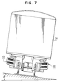
- Figure 7 illustrates the second embodiment of the cooling apparatus according to the present invention in a state that it is mounted on a railway vehicle.
- the refrigerant liquefied due to heat radiation must be returned into the cooling block.
- a bank ⁇ of the railway track is not greater than 7°.
- a bending angle ⁇ of the heat pipe is set to be not greater than 83° so that the liquefied refrigerant can be returned into the cooling block constantly.
Abstract
Description
- The present invention relates to a cooling apparatus for electronic elements, and more particularly, to a cooling apparatus which is suitable to cool semiconductor elements such as transistors and thyristers.
- Examples of the apparatus for cooling the electronic elements such as transistor and thyrister by radiating heat generated therefrom are disclosed in Japanese Patent Unexamined Publication Nos. 63-254754 and 1-192148. The cooling apparatus disclosed in the latter publication comprises an electronic device, a metallic block which serves as a heatsink of the electronic device, a plurality of heat pipes each extending in the vertical direction with one end thereof inserted in the metallic block and having a plurality of horizontal cooling fins provided at the other end thereof, a thermal conductive electric insulator disposed between the electronic device and the metallic block, conductor metals formed integrally with the thermal conductive electric insulator or both surfaces thereof, a duct which envelops the cooling fins, and a fan to supply cold wind to the duct. The thermal conductive electric insulator having the conductor metals formed integrally therewith, the electronic device and the metallic block are kept in pressure contact with each other or bonded together by means of bonding agent.
- Heat of the electronic device is transferred to the metallic block through the conductor metal, the thermal conductive electric insulator and the other conductor metal. Heat transferred to the metallic block is transferred to a refrigerant sealingly contained in the heat pipes and it evaporates the refrigerant. The evaporated refrigerant moves upwards within the heat pipes to the other ends thereof where the radiation fins are provided. At the other ends, heat is removed by the cold wind supplied by the fan, so that the refrigerant is liquefied and returned to the one ends of the heat pipes. In this way, heat of the electronic device is dissipated into the air.
- In the cooling apparatus described above, since the thermal conductive electric insulator having the conductor metals formed integrally on the both surfaces thereof, the electronic device and the metallic block are bonded together by means of the bonding agent, when it becomes necessary to change the design of the electronic device, the whole device cooling apparatus must be remodeled, resulting in that the apparatus is very uneconomical and has little flexibility to change of the design.
- In case that the thermal conductive electric insulator having the conductor metals formed integrally on the both surfaces thereof, the electronic device and the metallic block are kept in pressure contact with each other, it is possible to change only the electronic device, and however, there arises a problem that the positioning between the electronic device the design of which is changed and the metallic block is not easy actually. Further, in the case of being kept in pressure contact, contact thermal resistance is generated between the pressure contact surfaces of the electronic device and the conductor metal and between the pressure contact surfaces of the conductor metal and the metallic block, resulting in a problem that the thermal conductivity is deteriorated.
- In addition, since the radiation fins extend in the horizontal direction, the air warmed by the radiation fins is hindered from moving upwards by the radiation fins themselves. For this reason, heat radiation by natural convection is not sufficient and, hence, the fan for the forced cooling is required.
- Moreover, since the heat pipes extend in the vertical direction, there is a problem that the heightwise length of the cooling apparatus is increased. Further, in case that the calorific value of the electronic device is large, it is necessary to increase the radiation capacities of the metallic block and the heat pipes. In this case, however, the widthwise length of the metallic block and the number of the heat pipes must be increased, resulting in a problem that the widthwise length of the cooling apparatus is increased.
- An object of the present invention is to provide a cooling apparatus for electronic deive which is capable of easily coping with change of the design of the electronic device at a low cost without deteriorating the thermal conductivity, achieving a good heat radiation by natural convection and achieving a high degree of freedom in changing the radiation capacity.
- A cooling apparatus for electronic device according to the present invention comprises an electronic element unit which comprises a base member, a thermal conductive electric insulating layer soldered to the base member and a plurality of electronic elements soldered to the thermal conductive electric insulating layer, at least one cooling unit which is detachably kept in pressure contact with the base member of the electronic element unit and comprises a cooling block, at least one heat pipe having a refrigerant sealingly contained therein and inserted in the cooling block at one end thereof in the vertical direction and a plurality of radiation fins provided at the other end of the at least one heat pipe substantially perpendicular to an axis of the heat pipe, and means for detachably keeping the electronic element unit and the cooling unit in pressure contact with each other.
- According to an embodiment, the other end of the heat pipe extends obliquely with a predetermined angle with respect to the inserted portion thereof. In this case, it is preferred that the predetermined angle is not greater than 90° and, particularly, not greater than 83°.
- In order to attain a good thermal conductivity, the cooling block is made of ceramic or metal. Further, the refrigerant sealingly contained in the heat pipe is water.
- According to another embodiment, a plurality of cooling units are arranged in the vertical direction.
- It is preferred that thermal conductive grease is sandwiched between the base member of the electronic device unit and the cooling unit. In such case, it is preferred that at least one of the pressure contact surfaces of the base member and the cooling unit is formed therein with a plurality of microgrooves.
- The cooling unit may comprise a fan duct which extends in parallel with the radiation fins so as to envelop the same therein and a fan which is disposed in the fan duct so as to produce air currents directed toward the radiation fins.
- Since the cooling apparatus comprises the electronic element unit, the cooling unit and the means for detachably keeping these units in pressure contact with each other, when it becomes necessary to change the design of some electronic elements in the electronic element unit, it is possible to detach the electronic element unit, change the electronic elements and bring the electronic element unit and the cooling unit into pressure contact with each other again by the pressure contact means. Further, the positioning between the electronic element unit and the cooling unit can be performed automatically by the pressure contact means. Namely, the cooling apparatus according to the present invention has a good flexibility to change of the design of the electronic elements and is capable of changing the design at a low cost.
- Moreover, in the electronic element unit, the electronic elements are soldered to the thermal conductive electric insulating layer and the thermal conductive electric insulating layer is soldered to the base member, so that there is no possibility of generation of the contact thermal resistance between them. The portion where the contact thermal resistance is generated is only the pressure contact surface between the base member of the electronic element unit and the cooling block of the cooling unit. Therefore, heat of the electronic element unit can be transferred to the cooling unit satisfactorily, so that cooling of the electronic element unit can be performed sufficiently. Further, since the electronic elements and the base member are electrically isolated from each other in the electronic element unit, there is no possibility that the electric current flows through the cooling unit. Accordingly, the refrigerant to be sealingly contained in the heat pipe does not need to have an electric insulation. Therefore, it becomes possible to use water as the refrigerant of the heat pipe.
- In addition, since the other end of the heat pipe where the radiation fins are provided extends obliquely with respect to the portion thereof which is inserted in the cooling block in the vertical direction, the radiation fins are made to extend substantially in the vertical direction. For this reason, the air warmed by the radiation fins is allowed to flow upwards through the radiation fins, resulting in that heat can be dissipated satisfactorily due to natural convection. Since heat radiation can be performed satisfactorily without equipping any fan, it is possible to improve the reliability of the cooling apparatus.
- Further, since the other end portion of the heat pipe where the radiation fins are provided extends obliquely with respect to the vertical direction, a plurality of cooling units can be arranged in multiple stages in the vertical direction. Accordingly, it is possible to change the cooling capacity of the cooling unit in accordance with the calorific value of the electronic device unit without increasing the widthwise length of the cooling apparatus.
-
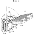
- Figure 1 is a partly broken-away perspective view of a first embodiment of a cooling apparatus for electronic device according to the present invention;
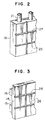
- Figure 2 is a perspective view of a cooling block of a cooling unit of the cooling apparatus according to the present invention;
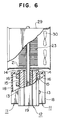
- Figure 3 is a perspective view of a base member of an electronic element unit of the cooling apparatus according to the present invention;
- Figure 4 is a partly broken-away side view of a second embodiment of the cooling apparatus according to the present invention;
- Figure 5 is a partly broken-away side view of a third embodiment of the cooling apparatus according to the present invention;
- Figure 6 is a partly broken-away side view of a fourth embodiment of the cooling apparatus according to the present invention; and
- Figure 7 is a partly sectioned schematic front view of a vehicle on which the second embodiment of the cooling apparatus of the present invention is mounted.
- Description will be given of a first embodiment of a cooling apparatus according to the present invention with reference to Figure 1. A cooling apparatus for
electronic device 10 comprises an electronic element unit 11, acooling unit 12 andbolts 13 by means of which these units are detachably kept in pressure contact with each other. - The electronic element unit 11 has a
base member 14 made of copper. A thermal conductiveelectric insulating layer 15 is soldered to one of the surfaces of thebase member 14, and a plurality ofelectronic elements 16 including thyrister and transistor, for example, are soldered to the thermal conductiveelectric insulating layer 15.Resin 17 is molded around theelectronic elements 16, and the surface of the moldedresin 17 is reinforced byplastic 18. As occasion demands, theresin 17 and the reinforcingplastic 18 may be dispensed with. - The
cooling unit 12 has acooling block 19 which is made of copper or ceramic and kept in contact with the other surface of thebase member 14. Thecooling block 19 is formed therein with a plurality ofholes 20 extending in the vertical direction. In theseholes 20 is press-fitted at least oneheat pipe 21 in which a refrigerant, e.g.,water 22 is sealingly contained. Theheat pipe 21 extends, at a position where it is projected out of thecooling block 19, obliquely so as to make a predetermined angle α of not greater than 90° with respect to the vertical line, and a plurality ofradiation fins 23 are provided in the end portion of theheat pipe 21 so as to extend in the direction perpendicular to the axis of theheat pipe 21. In other words, the plurality ofradiation fins 23 extend substantially in the vertical direction. - The
cooling block 19 is formed in position with through holes (not shown) which extend in the lateral direction, and thebase member 14 is formed in position corresponding to these through holes with threaded holes (not shown). Thebolts 13 are passed through the through holes and screwed in the threaded holes. By so doing, thebase member 14 and thecooling block 19 are kept in pressure contact with each other. - Between the contact surface of the
base member 14 and the contact surface of thecooling block 19, thermalconductive grease 24 may be sandwiched as shown in Figure 1. In this case, as shown in Figures 2 and 3, it is preferred that at least one of contact surfaces 26 and 25 of thebase member 14 and thecooling block 19 is formed therein withgrooves conductive grease 24. The reason is that, as thebolts 13 are screwed in, the contact surface of thebase member 14 and the contact surface of thecooling block 19 are kept in pressure contact with each other and the excessive thermal conductive grease is received in thegrooves - Since the
electronic elements 16 are soldered to the thermal conductive electric insulatinglayer 15, there is no possibility of generation of the contact thermal resistance between them. Accordingly, heat generated by theelectronic element 16 is transferred efficiently to the thermal conductive electric insulatinglayer 15. Since the thermal conductive electric insulatinglayer 15 is soldered to thebase member 14, there is no possibility of generation of the contact thermal resistance between them as well. Accordingly, heat transferred to the thermal conductive electric insulatinglayer 15 is transmitted effectively to thebase member 14. Heat transmitted to thebase member 14 is transferred to thecooling block 19 so as to heat the refrigerant (water) in theheat pipe 21, resulting in that the refrigerant is evaporated. The evaporated refrigerant moves upwards within theheat pipe 21 to the other ends thereof where theradiation fins 23 are provided. The air warmed by theradiation fins 23 due to heat exchange between theradiation fins 23 and the ambient air moves upwards through theradiation fins 23 without being hindered thereby since the radiation fins extend substantially in the vertical direction, thereby causing natural convection to occur. As a result, the radiation fins can be supplied with cold air at all times so that heat dissipation from the radiation fins to the ambient air can be performed effectively. In consequence, the refrigerant is liquefied and returned to the cooling block. In this way, heat of the electronic elements can be dissipated into the ambient air effectively. - In the embodiment described above, since the
cooling apparatus 10 comprises the electronic element unit 11, the coolingunit 12 and themeans 13 for detachably keeping these units in pressure contact with each other, when it becomes necessary to change the design of theelectronic elements 16 in the electronic element unit 11, it is possible to detach the electronic element unit 11, change theelectronic elements 16 and bring the electronic element unit 11 and thecooling unit 12 into pressure contact with each other again by the pressure contact means 13. Further, the positioning between the electronic element unit 11 and thecooling unit 12 can be per-formed automatically by the pressure contact means 13. Namely, the cooling apparatus according to the present invention has a good flexibility to change of the design of the electronic elements and is capable of changing the design at a low cost. - Moreover, in the electronic element unit 11, the
electronic elements 16 are soldered to the thermal conductive electric insulatinglayer 15 and the thermal conductive electric insulatinglayer 15 is soldered to thebase member 14, so that there is no possibility of generation of the contact thermal resistance between them. The portion where the contact thermal resistance is generated is only the pressure contact surface between thebase member 14 of the electronic element unit 11 and thecooling block 19 of the coolingunit 12. Therefore, heat of the electronic element unit 11 can be transferred to thecooling unit 12 satisfactorily, so that cooling of the electronic element unit 11 can be performed sufficiently. Further, since theelectronic elements 16 and thebase member 14 are electrically isolated from each other in the electronic element unit 11, there is no possibility that the electric current flows through the coolingunit 12. Accordingly, the refrigerant 22 to be sealingly contained in theheat pipe 21 does not need to have an electric insulation. Therefore, it becomes possible to use water as the refrigerant of theheat pipe 21. - In addition, since the other end of the
heat pipe 21 where theradiation fins 23 are provided extends obliquely with respect to the portion thereof which is inserted in thecooling block 19 in the vertical direction, theradiation fins 23 are made to extend substantially in the vertical direction. For this reason, the air warmed by theradiation fins 23 is allowed to flow upwards through theradiation fins 23, resulting in that heat can be dissipated satisfactorily due to natural convection. Since heat radiation can be performed satisfactorily without equipping any fan, it is possible to improve the reliability of the cooling apparatus. - Figure 4 illustrates a second embodiment of the cooling apparatus according to the present invention. In the second embodiment, a plurality of cooling
units 12 are mounted on thebase member 14 of a single electronic element unit 11 so as to be arranged in multiple stages in the vertical direction, and the structures of the electronic element unit 11 and thecooling unit 12 are the same as those of the first embodiment. - In the second embodiment, since the air warmed by the
radiation fins 23 is allowed to flow upwards through theradiation fins 23, heat can be dissipated satisfactorily due to natural convection. Particularly, the air warmed by theradiation fins 23 of the lower cooling unit moves upwards to mix with the low-temperature air in a space defined between the upper and lower cooling units, so that the radia-tion fins of the upper cooling unit can be cooled effectively. Since it is possible to radiate heat satisfactorily without equipping any fan, the reliability of the cooling apparatus can be improved. - Further, since the other end portion of the heat pipe where the radiation fins are provided extends obliquely with respect to the vertical direction, a plurality of cooling units can be arranged in multiple stages in the vertical direction. Accordingly, it is possible to change the cooling capacity of the cooling unit in accordance with the calorific value of the electronic element unit without increasing the widthwise length of the cooling apparatus.
- In a third embodiment shown in Figure 5, the
heat pipe 21 of the second embodiment is bent to an angle of about 90°, afan duct 29 extends in parallel with the radiation fins so as to envelop the radiation fins therein, andfans 30 are disposed in thefan duct 29 so as to produce air currents directed toward the radiation fins. This construction is suitable when heat radiation due to natural convection is not sufficient. - A fourth embodiment shown in Figure 6 comprises a
single cooling unit 12 and two electronic element units 11 contrary to the second embodiment. Theheat pipe 21 of the coolingunit 12 extends vertically and the electronic element units 11 are kept in pressure contact with the both surfaces of thecooling block 19 by means of thebolts 13. - Figure 7 illustrates the second embodiment of the cooling apparatus according to the present invention in a state that it is mounted on a railway vehicle. The refrigerant liquefied due to heat radiation must be returned into the cooling block. On the other hand, a bank β of the railway track is not greater than 7°. For this reason, a bending angle α of the heat pipe is set to be not greater than 83° so that the liquefied refrigerant can be returned into the cooling block constantly.
Claims (11)
- A cooling apparatus (10) for electronic device comprising:
an electronic element unit (11) comprising a base member (14) and a plurality of electronic elements (16); and
a cooling unit (12) comprising a cooling block (19) which is in contact with said electronic element unit (11), at least one heat pipe (21) having a refrigerant (22) sealingly contained therein and inserted in said cooling block (19) at one end thereof, and a plurality of radiation fins (23) provided at the other end of said at least one heat pipe (21) substantially perpendicular to an axis of said heat pipe (21),
characterized in that a thermal conductive electric insulating layer (15) is soldered to said base member (14) of said electronic element unit (11), said plurality of electronic elements (16) are soldered to said thermal conductive electric insulating layer (15), and means (13) is provided for detachably keeping said electronic element unit (11) and said cooling unit (12) in pressure contact with each other. - A cooling apparatus according to claim 1, wherein the other end of said heat pipe (21) extends obliquely with a predetermined angle (α) with respect to said inserted portion thereof.
- A cooling apparatus according to claim 2, wherein said predetermined angle (α) is not greater than 90°.
- A cooling apparatus according to claim 3, wherein said predetermined angle (α) is not greater than 83°.
- A cooling apparatus according to claim 1 or 2, wherein said cooling block (19) is made of ceramic.
- A cooling apparatus according to claim 1 or 2, wherein said cooling block (19) is made of metal.
- A cooling apparatus according to claim 1 or 2, wherein said refrigerant (22) is water.
- A cooling apparatus according to claim 2, wherein said at least one cooling unit (12) includes a plurality of cooling units (12) which are arranged in the vertical direction.
- A cooling apparatus according to claim 1 or 2, wherein thermal conductive grease (24) is sandwiched between said base member (14) of said electronic element unit (11) and said cooling unit (12).
- A cooling apparatus according to claim 9, wherein at least one of pressure contact surfaces (26, 25) of said base member (14) and said cooling unit (12) is formed therein with a plurality of grooves (28, 27).
- A cooling apparatus according to claim 1 or 2, wherein said cooling unit (12) further comprises a fan duct (29) which extends in parallel with said radiation fins (23) so as to envelop the same therein, and a fan (30) which is disposed in said fan duct (29) so as to produce air currents directed toward said radiation fins (23).
Applications Claiming Priority (2)
| Application Number | Priority Date | Filing Date | Title |
|---|---|---|---|
| JP4176497A JP3067399B2 (en) | 1992-07-03 | 1992-07-03 | Semiconductor cooling device |
| JP176497/92 | 1992-07-03 |
Publications (3)
| Publication Number | Publication Date |
|---|---|
| EP0577099A2 true EP0577099A2 (en) | 1994-01-05 |
| EP0577099A3 EP0577099A3 (en) | 1994-03-16 |
| EP0577099B1 EP0577099B1 (en) | 1998-02-04 |
Family
ID=16014692
Family Applications (1)
| Application Number | Title | Priority Date | Filing Date |
|---|---|---|---|
| EP93110438A Expired - Lifetime EP0577099B1 (en) | 1992-07-03 | 1993-06-30 | Cooling apparatus for electronic elements |
Country Status (8)
| Country | Link |
|---|---|
| US (1) | US5925929A (en) |
| EP (1) | EP0577099B1 (en) |
| JP (1) | JP3067399B2 (en) |
| KR (1) | KR970005711B1 (en) |
| CN (1) | CN1029056C (en) |
| AU (1) | AU651765B2 (en) |
| DE (1) | DE69316795T2 (en) |
| ZA (1) | ZA934733B (en) |
Cited By (12)
| Publication number | Priority date | Publication date | Assignee | Title |
|---|---|---|---|---|
| FR2703829A1 (en) * | 1993-04-08 | 1994-10-14 | Fuji Electric Co Ltd | Conductive contact structure for two conductors. |
| EP0630777A1 (en) * | 1993-06-22 | 1994-12-28 | Hitachi, Ltd. | Power converting device for reducing induction trouble |
| EP0771138A1 (en) * | 1995-10-26 | 1997-05-02 | The Furukawa Electric Co., Ltd. | Cooling device for electric components in a casing of a travelling structure |
| DE29704885U1 (en) * | 1997-03-19 | 1998-04-30 | Siemens Ag | Arrangement for dissipating heat from a heat source arranged in a housing |
| EP1146294A1 (en) * | 2000-04-13 | 2001-10-17 | Ha Woo Lee | Hot-air heating system |
| CN102291957A (en) * | 2011-07-26 | 2011-12-21 | 阳光电源股份有限公司 | Outdoor power supply box |
| EP2429274A3 (en) * | 2010-08-31 | 2013-10-30 | Hitachi Ltd. | Cooling system for onboard electrical power converter, and electrical power converter for railway vehicle |
| FR2993430A1 (en) * | 2012-07-11 | 2014-01-17 | Still Gmbh | ELECTRIC HANDLING TROLLEY |
| US20140290929A1 (en) * | 2013-03-26 | 2014-10-02 | Ge Energy Power Conversion Technology Ltd | Heat pipe heat sink with heating unit |
| EP2784812A3 (en) * | 2013-03-26 | 2015-04-29 | GE Energy Power Conversion Technology Ltd | Heat pipe sink for high power density |
| WO2017158253A1 (en) * | 2016-03-15 | 2017-09-21 | Institut Vedecom | Cooled electronic power module, motor and vehicle comprising such a module |
| WO2017158252A1 (en) * | 2016-03-15 | 2017-09-21 | Institut Vedecom | Power electronic module for controlling a multiphase electrical system, electric motor and vehicle equipped with this module |
Families Citing this family (44)
| Publication number | Priority date | Publication date | Assignee | Title |
|---|---|---|---|---|
| JP3225457B2 (en) * | 1995-02-28 | 2001-11-05 | 株式会社日立製作所 | Semiconductor device |
| JP3352362B2 (en) * | 1997-07-14 | 2002-12-03 | 三菱電機株式会社 | Heat sink |
| US6188575B1 (en) * | 1998-06-30 | 2001-02-13 | Intersil Corporation | Heat exchanging chassis and method |
| JP3420945B2 (en) * | 1998-08-14 | 2003-06-30 | 株式会社東芝 | Power converter |
| US6169660B1 (en) * | 1999-11-01 | 2001-01-02 | Thermal Corp. | Stress relieved integrated circuit cooler |
| US6422304B1 (en) * | 2000-08-07 | 2002-07-23 | Shari Lynn Slovikosky | System and method for cooling a central processing unit |
| US6504721B1 (en) * | 2000-09-29 | 2003-01-07 | Intel Corporation | Thermal cooling apparatus |
| JP2002168547A (en) * | 2000-11-20 | 2002-06-14 | Global Cooling Bv | Cpu cooling device using siphon |
| TW543828U (en) * | 2001-07-12 | 2003-07-21 | Foxconn Prec Components Co Ltd | Assembly of heating-tube heat sink |
| TW572246U (en) * | 2001-07-26 | 2004-01-11 | Jiun-Fu Liou | Heat dissipating module with a self rapid heat conduction |
| US6885553B2 (en) * | 2002-09-27 | 2005-04-26 | Rockwell Automation Technologies, Inc. | Bus bar assembly for use with a compact power conversion assembly |
| US6956742B2 (en) * | 2002-09-27 | 2005-10-18 | Rockwell Automation Technologies, Inc. | Compact liquid converter assembly |
| US7068507B2 (en) | 2002-09-27 | 2006-06-27 | Rockwell Automation Technologies, Inc. | Compact liquid converter assembly |
| US6721181B1 (en) | 2002-09-27 | 2004-04-13 | Rockwell Automation Technologies, Inc. | Elongated heat sink for use in converter assemblies |
| US6822850B2 (en) * | 2002-09-27 | 2004-11-23 | Rockwell Automation Technologies, Inc. | Laminated bus bar for use with a power conversion configuration |
| US6695039B1 (en) | 2003-02-25 | 2004-02-24 | Delphi Technologies, Inc. | Orientation insensitive thermosiphon assembly for cooling electronic components |
| TWM244509U (en) * | 2003-07-16 | 2004-09-21 | Hon Hai Prec Ind Co Ltd | A heat pipe radiator |
| TWM244561U (en) * | 2003-09-12 | 2004-09-21 | Hon Hai Prec Ind Co Ltd | A heat pipe radiator |
| CN2657082Y (en) * | 2003-10-18 | 2004-11-17 | 鸿富锦精密工业(深圳)有限公司 | Radiator for heat pipe |
| KR101041796B1 (en) * | 2003-12-02 | 2011-06-17 | 엘지전자 주식회사 | A dryer and method for compensating moisture of the same |
| JP3799352B2 (en) * | 2003-12-22 | 2006-07-19 | 東芝トランスポートエンジニアリング株式会社 | Power converter |
| JP3822612B2 (en) * | 2004-03-15 | 2006-09-20 | 東芝トランスポートエンジニアリング株式会社 | Railway vehicle power converter |
| JP4876975B2 (en) * | 2007-03-02 | 2012-02-15 | 株式会社日立製作所 | Cooling device and heat receiving member for electronic equipment |
| US7762316B2 (en) * | 2007-08-06 | 2010-07-27 | Man Zai Industrial Co., Ltd. | Heat-dissipating device with high heat-dissipating efficiency |
| US20100027260A1 (en) * | 2008-07-30 | 2010-02-04 | Lustrous International Technology Ltd. | Light emitting diode lamp |
| FR2949181B1 (en) * | 2009-08-14 | 2017-02-24 | Splitted Desktop Systems | THERMAL DISSIPATOR FOR ELECTRONIC COMPONENTS AND ASSOCIATED METHOD OF ASSEMBLY |
| JP2012059952A (en) * | 2010-09-09 | 2012-03-22 | Mitsubishi Electric Corp | Electronic apparatus cooling structure |
| JP5517850B2 (en) * | 2010-09-09 | 2014-06-11 | 三菱電機株式会社 | Electronic equipment heat dissipation structure |
| CN103167780B (en) * | 2011-12-16 | 2016-06-08 | 台达电子企业管理(上海)有限公司 | Power model combined radiator assembly |
| EP2704190A1 (en) * | 2012-09-03 | 2014-03-05 | ABB Technology AG | Modular cooling system |
| DE102014103481A1 (en) * | 2014-03-14 | 2015-03-12 | Semikron Elektronik Gmbh & Co. Kg | Power semiconductor device |
| JP2015223863A (en) * | 2014-05-26 | 2015-12-14 | 三菱電機株式会社 | Air conditioner for vehicle |
| CN107003077A (en) * | 2014-12-25 | 2017-08-01 | 三菱铝株式会社 | Cooler |
| CN104812217B (en) * | 2015-04-17 | 2017-09-29 | 华为技术有限公司 | Rack and cooling system |
| KR20160139094A (en) * | 2015-05-26 | 2016-12-07 | 엘에스산전 주식회사 | Closed cabinet for electric device having heat pipe |
| US10178803B2 (en) * | 2016-03-11 | 2019-01-08 | Eaton Intelligent Power Limited | Thermosyphon cooling apparatus with isolation of cooled components |
| DE102016208119A1 (en) * | 2016-05-11 | 2017-11-16 | Siemens Aktiengesellschaft | Heat sink for power semiconductors |
| KR102147658B1 (en) * | 2017-12-08 | 2020-08-26 | 주식회사 케이엠더블유 | A cooling apparatus for electronic elements |
| DE102018202303B4 (en) * | 2018-02-15 | 2022-06-15 | Robert Bosch Gmbh | Sensor system for mounting a sensor array on a vehicle |
| JP2020009024A (en) * | 2018-07-04 | 2020-01-16 | 東芝テック株式会社 | Processing terminal |
| JP7050996B2 (en) * | 2019-02-22 | 2022-04-08 | 三菱電機株式会社 | Cooling device and power conversion device |
| JP2022068579A (en) * | 2020-10-22 | 2022-05-10 | 株式会社東芝 | Power conversion device |
| DE102020131066A1 (en) * | 2020-11-24 | 2022-05-25 | Miele & Cie. Kg | Cooking appliance with a cooling device and cooling device for a cooking appliance |
| CN114659394A (en) * | 2022-03-31 | 2022-06-24 | 阳光电源股份有限公司 | Phase change heat exchanger and heat exchange core body thereof |
Citations (4)
| Publication number | Priority date | Publication date | Assignee | Title |
|---|---|---|---|---|
| FR2288395A1 (en) * | 1974-10-17 | 1976-05-14 | Gen Electric | Heat pipe cooled power semiconductor device - has two thin thermally conductive pressure plates in contact with support plates |
| DE2825582A1 (en) * | 1977-06-13 | 1978-12-21 | Gen Electric | HEAT REMOVAL DEVICE FOR SEMI-CONDUCTOR MODULE |
| JPH01192148A (en) * | 1988-01-28 | 1989-08-02 | Mitsubishi Electric Corp | Cooling device for electric heating element |
| EP0363687A2 (en) * | 1988-09-20 | 1990-04-18 | Nec Corporation | Cooling structure for electronic components |
Family Cites Families (21)
| Publication number | Priority date | Publication date | Assignee | Title |
|---|---|---|---|---|
| SE354943B (en) * | 1970-02-24 | 1973-03-26 | Asea Ab | |
| US3818983A (en) * | 1972-09-18 | 1974-06-25 | Borg Warner | Cooled enclosure |
| US3852806A (en) * | 1973-05-02 | 1974-12-03 | Gen Electric | Nonwicked heat-pipe cooled power semiconductor device assembly having enhanced evaporated surface heat pipes |
| US3852803A (en) * | 1973-06-18 | 1974-12-03 | Gen Electric | Heat sink cooled power semiconductor device assembly having liquid metal interface |
| US4072188A (en) * | 1975-07-02 | 1978-02-07 | Honeywell Information Systems Inc. | Fluid cooling systems for electronic systems |
| JPS57164566A (en) * | 1981-04-03 | 1982-10-09 | Nec Corp | Semiconductor device |
| US4567505A (en) * | 1983-10-27 | 1986-01-28 | The Board Of Trustees Of The Leland Stanford Junior University | Heat sink and method of attaching heat sink to a semiconductor integrated circuit and the like |
| JPS624349A (en) * | 1985-07-01 | 1987-01-10 | Fujitsu Ltd | Method of cooling semiconductor component |
| JPS6210594A (en) * | 1985-07-08 | 1987-01-19 | Hitachi Cable Ltd | Heat pipe |
| JPS62238653A (en) * | 1986-04-09 | 1987-10-19 | Nec Corp | Cooling structure |
| JPS63254754A (en) * | 1987-04-10 | 1988-10-21 | Mitsubishi Electric Corp | Cooling device for electronic element body |
| JPH0719864B2 (en) * | 1988-02-10 | 1995-03-06 | 日本電気株式会社 | Integrated circuit cooling structure |
| JPH0812890B2 (en) * | 1988-05-24 | 1996-02-07 | 富士通株式会社 | Module sealing method |
| JP2682849B2 (en) * | 1988-08-31 | 1997-11-26 | 京セラ株式会社 | Heat exchanger and manufacturing method thereof |
| JPH02291157A (en) * | 1989-04-28 | 1990-11-30 | Mitsubishi Electric Corp | Semiconductor device |
| US5095404A (en) * | 1990-02-26 | 1992-03-10 | Data General Corporation | Arrangement for mounting and cooling high density tab IC chips |
| JPH047860A (en) * | 1990-04-26 | 1992-01-13 | Toshiba Corp | Semiconductor stack |
| US5046552A (en) * | 1990-07-20 | 1991-09-10 | Minnesota Mining And Manufacturing | Flow-through heat transfer apparatus with movable thermal via |
| JPH04225790A (en) * | 1990-12-27 | 1992-08-14 | Furukawa Electric Co Ltd:The | Heat pipe type radiator and manufacture thereof |
| JPH0563385A (en) * | 1991-08-30 | 1993-03-12 | Hitachi Ltd | Electronic apparatus and computer provided with heat pipe |
| GB9914025D0 (en) * | 1999-06-17 | 1999-08-18 | Zeneca Ltd | Chemical compounds |
-
1992
- 1992-07-03 JP JP4176497A patent/JP3067399B2/en not_active Expired - Lifetime
-
1993
- 1993-06-28 AU AU41580/93A patent/AU651765B2/en not_active Expired
- 1993-06-28 KR KR1019930011827A patent/KR970005711B1/en not_active IP Right Cessation
- 1993-06-30 EP EP93110438A patent/EP0577099B1/en not_active Expired - Lifetime
- 1993-06-30 DE DE69316795T patent/DE69316795T2/en not_active Expired - Fee Related
- 1993-07-01 ZA ZA934733A patent/ZA934733B/en unknown
- 1993-07-02 CN CN93108095A patent/CN1029056C/en not_active Expired - Lifetime
-
1996
- 1996-10-28 US US08/738,710 patent/US5925929A/en not_active Expired - Lifetime
Patent Citations (4)
| Publication number | Priority date | Publication date | Assignee | Title |
|---|---|---|---|---|
| FR2288395A1 (en) * | 1974-10-17 | 1976-05-14 | Gen Electric | Heat pipe cooled power semiconductor device - has two thin thermally conductive pressure plates in contact with support plates |
| DE2825582A1 (en) * | 1977-06-13 | 1978-12-21 | Gen Electric | HEAT REMOVAL DEVICE FOR SEMI-CONDUCTOR MODULE |
| JPH01192148A (en) * | 1988-01-28 | 1989-08-02 | Mitsubishi Electric Corp | Cooling device for electric heating element |
| EP0363687A2 (en) * | 1988-09-20 | 1990-04-18 | Nec Corporation | Cooling structure for electronic components |
Non-Patent Citations (2)
| Title |
|---|
| PATENT ABSTRACTS OF JAPAN vol. 13 no. 483, 2nd November 1989 (E-839); & JP-A-1 192 148 * |
| W. Bresch, "Hybride Leistungs-IC", Technische Rundschau, 78 (1986), Nov., No. 45, Bern, Schweiz, 106-109 * |
Cited By (17)
| Publication number | Priority date | Publication date | Assignee | Title |
|---|---|---|---|---|
| FR2703829A1 (en) * | 1993-04-08 | 1994-10-14 | Fuji Electric Co Ltd | Conductive contact structure for two conductors. |
| US5629562A (en) * | 1993-04-08 | 1997-05-13 | Fuji Electric Co., Ltd. | Conductive contact structure for two conductors |
| EP0630777A1 (en) * | 1993-06-22 | 1994-12-28 | Hitachi, Ltd. | Power converting device for reducing induction trouble |
| US5583385A (en) * | 1993-06-22 | 1996-12-10 | Hitachi, Ltd. | Power converting device for reducing an induction problem |
| EP0771138A1 (en) * | 1995-10-26 | 1997-05-02 | The Furukawa Electric Co., Ltd. | Cooling device for electric components in a casing of a travelling structure |
| DE29704885U1 (en) * | 1997-03-19 | 1998-04-30 | Siemens Ag | Arrangement for dissipating heat from a heat source arranged in a housing |
| EP1146294A1 (en) * | 2000-04-13 | 2001-10-17 | Ha Woo Lee | Hot-air heating system |
| EP2429274A3 (en) * | 2010-08-31 | 2013-10-30 | Hitachi Ltd. | Cooling system for onboard electrical power converter, and electrical power converter for railway vehicle |
| US8879259B2 (en) | 2010-08-31 | 2014-11-04 | Hitachi, Ltd. | Cooling system for onboard electrical power converter, and electrical power converter for railway vehicle |
| CN102291957A (en) * | 2011-07-26 | 2011-12-21 | 阳光电源股份有限公司 | Outdoor power supply box |
| FR2993430A1 (en) * | 2012-07-11 | 2014-01-17 | Still Gmbh | ELECTRIC HANDLING TROLLEY |
| US20140290929A1 (en) * | 2013-03-26 | 2014-10-02 | Ge Energy Power Conversion Technology Ltd | Heat pipe heat sink with heating unit |
| EP2784812A3 (en) * | 2013-03-26 | 2015-04-29 | GE Energy Power Conversion Technology Ltd | Heat pipe sink for high power density |
| WO2017158253A1 (en) * | 2016-03-15 | 2017-09-21 | Institut Vedecom | Cooled electronic power module, motor and vehicle comprising such a module |
| WO2017158252A1 (en) * | 2016-03-15 | 2017-09-21 | Institut Vedecom | Power electronic module for controlling a multiphase electrical system, electric motor and vehicle equipped with this module |
| FR3049158A1 (en) * | 2016-03-15 | 2017-09-22 | Inst Vedecom | ELECTRONIC POWER MODULE FOR CONTROLLING A MULTIPHASE ELECTRICAL SYSTEM, ELECTRIC MOTOR AND VEHICLE EQUIPPED WITH SAID MODULE |
| FR3049159A1 (en) * | 2016-03-15 | 2017-09-22 | Inst Vedecom | ELECTRONIC MODULE FOR COOLING POWER, ENGINE AND VEHICLE INCORPORATING SUCH A MODULE |
Also Published As
| Publication number | Publication date |
|---|---|
| KR970005711B1 (en) | 1997-04-19 |
| DE69316795T2 (en) | 1998-07-09 |
| ZA934733B (en) | 1994-01-24 |
| EP0577099A3 (en) | 1994-03-16 |
| DE69316795D1 (en) | 1998-03-12 |
| JP3067399B2 (en) | 2000-07-17 |
| US5925929A (en) | 1999-07-20 |
| CN1081788A (en) | 1994-02-09 |
| EP0577099B1 (en) | 1998-02-04 |
| JPH0621289A (en) | 1994-01-28 |
| CN1029056C (en) | 1995-06-21 |
| AU651765B2 (en) | 1994-07-28 |
| KR940006251A (en) | 1994-03-23 |
| AU4158093A (en) | 1994-01-13 |
Similar Documents
| Publication | Publication Date | Title |
|---|---|---|
| EP0577099B1 (en) | Cooling apparatus for electronic elements | |
| US5764483A (en) | Cooling unit for electronic equipment | |
| US5793611A (en) | Cooling device with thermally separated electronic parts on a monolithic substrate | |
| US6041850A (en) | Temperature control of electronic components | |
| US4204246A (en) | Cooling assembly for cooling electrical parts wherein a heat pipe is attached to a heat conducting portion of a heat conductive block | |
| US6840311B2 (en) | Compact thermosiphon for dissipating heat generated by electronic components | |
| US4009423A (en) | Liquid cooled heat exchanger for electronic power supplies | |
| US6352104B1 (en) | Heat sink with enhanced heat spreading and compliant interface for better heat transfer | |
| US6459576B1 (en) | Fan based heat exchanger | |
| JP2001119181A (en) | Cooling unit for electronic component and electronic apparatus | |
| JPH08255858A (en) | Cooling system of electronic package | |
| JPS6292455A (en) | Heat radiating equipment for output semiconductor element | |
| US7110256B2 (en) | Communication device | |
| JP2005136211A (en) | Cooling device | |
| US4682208A (en) | Transistor protection device | |
| US7239514B2 (en) | Heat transfer structure for electronic devices | |
| JP3566505B2 (en) | Inverter device | |
| JPH08213526A (en) | Circuit pack | |
| JPS5857679B2 (en) | electronic heat exchange unit | |
| JP3345855B2 (en) | heatsink | |
| US20060139892A1 (en) | Heat dissipating arrangement for an electronic appliance | |
| JP3359136B2 (en) | Cooler for semiconductor device | |
| KR20020034613A (en) | Parts cooling apparatus for electric/electronic equipments | |
| JPS59155158A (en) | Cooling structure of semiconductor device | |
| CN114746711A (en) | Cooling device and power conversion device |
Legal Events
| Date | Code | Title | Description |
|---|---|---|---|
| PUAI | Public reference made under article 153(3) epc to a published international application that has entered the european phase |
Free format text: ORIGINAL CODE: 0009012 |
|
| AK | Designated contracting states |
Kind code of ref document: A2 Designated state(s): CH DE FR LI |
|
| PUAL | Search report despatched |
Free format text: ORIGINAL CODE: 0009013 |
|
| AK | Designated contracting states |
Kind code of ref document: A3 Designated state(s): CH DE FR LI |
|
| 17P | Request for examination filed |
Effective date: 19940207 |
|
| 17Q | First examination report despatched |
Effective date: 19950804 |
|
| GRAG | Despatch of communication of intention to grant |
Free format text: ORIGINAL CODE: EPIDOS AGRA |
|
| GRAG | Despatch of communication of intention to grant |
Free format text: ORIGINAL CODE: EPIDOS AGRA |
|
| GRAH | Despatch of communication of intention to grant a patent |
Free format text: ORIGINAL CODE: EPIDOS IGRA |
|
| GRAH | Despatch of communication of intention to grant a patent |
Free format text: ORIGINAL CODE: EPIDOS IGRA |
|
| GRAA | (expected) grant |
Free format text: ORIGINAL CODE: 0009210 |
|
| AK | Designated contracting states |
Kind code of ref document: B1 Designated state(s): CH DE FR LI |
|
| REG | Reference to a national code |
Ref country code: CH Ref legal event code: NV Representative=s name: TROESCH SCHEIDEGGER WERNER AG Ref country code: CH Ref legal event code: EP |
|
| REF | Corresponds to: |
Ref document number: 69316795 Country of ref document: DE Date of ref document: 19980312 |
|
| ET | Fr: translation filed | ||
| PLBE | No opposition filed within time limit |
Free format text: ORIGINAL CODE: 0009261 |
|
| STAA | Information on the status of an ep patent application or granted ep patent |
Free format text: STATUS: NO OPPOSITION FILED WITHIN TIME LIMIT |
|
| 26N | No opposition filed | ||
| PGFP | Annual fee paid to national office [announced via postgrant information from national office to epo] |
Ref country code: FR Payment date: 20020416 Year of fee payment: 10 |
|
| PGFP | Annual fee paid to national office [announced via postgrant information from national office to epo] |
Ref country code: DE Payment date: 20020829 Year of fee payment: 10 |
|
| PGFP | Annual fee paid to national office [announced via postgrant information from national office to epo] |
Ref country code: CH Payment date: 20020913 Year of fee payment: 10 |
|
| PG25 | Lapsed in a contracting state [announced via postgrant information from national office to epo] |
Ref country code: LI Free format text: LAPSE BECAUSE OF NON-PAYMENT OF DUE FEES Effective date: 20030630 Ref country code: CH Free format text: LAPSE BECAUSE OF NON-PAYMENT OF DUE FEES Effective date: 20030630 |
|
| PG25 | Lapsed in a contracting state [announced via postgrant information from national office to epo] |
Ref country code: DE Free format text: LAPSE BECAUSE OF NON-PAYMENT OF DUE FEES Effective date: 20040101 |
|
| REG | Reference to a national code |
Ref country code: CH Ref legal event code: PL |
|
| PG25 | Lapsed in a contracting state [announced via postgrant information from national office to epo] |
Ref country code: FR Free format text: LAPSE BECAUSE OF NON-PAYMENT OF DUE FEES Effective date: 20040227 |
|
| REG | Reference to a national code |
Ref country code: FR Ref legal event code: ST |