EP0576352A1 - Dispositif de chauffage inductif homogène de produits plats métalliques au défilé - Google Patents
Dispositif de chauffage inductif homogène de produits plats métalliques au défilé Download PDFInfo
- Publication number
- EP0576352A1 EP0576352A1 EP93401605A EP93401605A EP0576352A1 EP 0576352 A1 EP0576352 A1 EP 0576352A1 EP 93401605 A EP93401605 A EP 93401605A EP 93401605 A EP93401605 A EP 93401605A EP 0576352 A1 EP0576352 A1 EP 0576352A1
- Authority
- EP
- European Patent Office
- Prior art keywords
- product
- heated
- coils
- heating
- induction heating
- Prior art date
- Legal status (The legal status is an assumption and is not a legal conclusion. Google has not performed a legal analysis and makes no representation as to the accuracy of the status listed.)
- Granted
Links
Images

Classifications
-
- H—ELECTRICITY
- H05—ELECTRIC TECHNIQUES NOT OTHERWISE PROVIDED FOR
- H05B—ELECTRIC HEATING; ELECTRIC LIGHT SOURCES NOT OTHERWISE PROVIDED FOR; CIRCUIT ARRANGEMENTS FOR ELECTRIC LIGHT SOURCES, IN GENERAL
- H05B6/00—Heating by electric, magnetic or electromagnetic fields
- H05B6/02—Induction heating
- H05B6/36—Coil arrangements
- H05B6/365—Coil arrangements using supplementary conductive or ferromagnetic pieces
-
- F—MECHANICAL ENGINEERING; LIGHTING; HEATING; WEAPONS; BLASTING
- F27—FURNACES; KILNS; OVENS; RETORTS
- F27B—FURNACES, KILNS, OVENS OR RETORTS IN GENERAL; OPEN SINTERING OR LIKE APPARATUS
- F27B9/00—Furnaces through which the charge is moved mechanically, e.g. of tunnel type; Similar furnaces in which the charge moves by gravity
- F27B9/06—Furnaces through which the charge is moved mechanically, e.g. of tunnel type; Similar furnaces in which the charge moves by gravity heated without contact between combustion gases and charge; electrically heated
- F27B9/062—Furnaces through which the charge is moved mechanically, e.g. of tunnel type; Similar furnaces in which the charge moves by gravity heated without contact between combustion gases and charge; electrically heated electrically heated
- F27B9/067—Furnaces through which the charge is moved mechanically, e.g. of tunnel type; Similar furnaces in which the charge moves by gravity heated without contact between combustion gases and charge; electrically heated electrically heated heated by induction
-
- F—MECHANICAL ENGINEERING; LIGHTING; HEATING; WEAPONS; BLASTING
- F27—FURNACES; KILNS; OVENS; RETORTS
- F27B—FURNACES, KILNS, OVENS OR RETORTS IN GENERAL; OPEN SINTERING OR LIKE APPARATUS
- F27B9/00—Furnaces through which the charge is moved mechanically, e.g. of tunnel type; Similar furnaces in which the charge moves by gravity
- F27B9/28—Furnaces through which the charge is moved mechanically, e.g. of tunnel type; Similar furnaces in which the charge moves by gravity for treating continuous lengths of work
-
- H—ELECTRICITY
- H05—ELECTRIC TECHNIQUES NOT OTHERWISE PROVIDED FOR
- H05B—ELECTRIC HEATING; ELECTRIC LIGHT SOURCES NOT OTHERWISE PROVIDED FOR; CIRCUIT ARRANGEMENTS FOR ELECTRIC LIGHT SOURCES, IN GENERAL
- H05B6/00—Heating by electric, magnetic or electromagnetic fields
- H05B6/02—Induction heating
- H05B6/10—Induction heating apparatus, other than furnaces, for specific applications
- H05B6/101—Induction heating apparatus, other than furnaces, for specific applications for local heating of metal pieces
- H05B6/103—Induction heating apparatus, other than furnaces, for specific applications for local heating of metal pieces multiple metal pieces successively being moved close to the inductor
- H05B6/104—Induction heating apparatus, other than furnaces, for specific applications for local heating of metal pieces multiple metal pieces successively being moved close to the inductor metal pieces being elongated like wires or bands
-
- H—ELECTRICITY
- H05—ELECTRIC TECHNIQUES NOT OTHERWISE PROVIDED FOR
- H05B—ELECTRIC HEATING; ELECTRIC LIGHT SOURCES NOT OTHERWISE PROVIDED FOR; CIRCUIT ARRANGEMENTS FOR ELECTRIC LIGHT SOURCES, IN GENERAL
- H05B6/00—Heating by electric, magnetic or electromagnetic fields
- H05B6/02—Induction heating
- H05B6/36—Coil arrangements
- H05B6/362—Coil arrangements with flat coil conductors
-
- H—ELECTRICITY
- H05—ELECTRIC TECHNIQUES NOT OTHERWISE PROVIDED FOR
- H05B—ELECTRIC HEATING; ELECTRIC LIGHT SOURCES NOT OTHERWISE PROVIDED FOR; CIRCUIT ARRANGEMENTS FOR ELECTRIC LIGHT SOURCES, IN GENERAL
- H05B6/00—Heating by electric, magnetic or electromagnetic fields
- H05B6/02—Induction heating
- H05B6/36—Coil arrangements
- H05B6/44—Coil arrangements having more than one coil or coil segment
-
- Y—GENERAL TAGGING OF NEW TECHNOLOGICAL DEVELOPMENTS; GENERAL TAGGING OF CROSS-SECTIONAL TECHNOLOGIES SPANNING OVER SEVERAL SECTIONS OF THE IPC; TECHNICAL SUBJECTS COVERED BY FORMER USPC CROSS-REFERENCE ART COLLECTIONS [XRACs] AND DIGESTS
- Y02—TECHNOLOGIES OR APPLICATIONS FOR MITIGATION OR ADAPTATION AGAINST CLIMATE CHANGE
- Y02P—CLIMATE CHANGE MITIGATION TECHNOLOGIES IN THE PRODUCTION OR PROCESSING OF GOODS
- Y02P10/00—Technologies related to metal processing
- Y02P10/25—Process efficiency
Definitions
- the present invention relates to a parade heating device, by induction, of flat products, in particular metallic.
- the heating in the parade by induction of flat products is carried out using coils which are arranged so as to surround the product to be heated by creating a magnetic field parallel to the external surface of this product in the direction scrolling (longitudinal flow).
- the internal dimensions of each winding depend on the shape of the product and its possible geometric defects.
- the product is "trapped" in the winding since it scrolls inside the fixed windings.
- a magnetic field is created perpendicular to the large faces of the product to be heated according to the technique known as "transverse flux in phase".
- transverse flux in phase there are two coils on either side of the product to be heated, opposite each of the faces of the latter, these coils being supplied at a frequency such that the magnetic field is through.
- the distance between the coils (which are mechanically separated from one another) and the product to be heated can be reduced to a strict minimum, which makes it possible to obtain increased efficiency of induction heating and improved electrical efficiency.
- the product to be heated is not trapped in the inductor, which makes it possible to intervene without difficulty in the event of disturbances in the progress of the process of heating in the runway.
- the present invention proposes to provide an original solution by producing an induction heating device leading to a ring distribution of the currents induced in the product to be heated, thereby ensuring heating of this product with satisfactory homogeneity of distribution and the possibility of adjusting the position of the inductor windings, relative to the product, which improves the heating efficiency as well as the security.
- the present invention relates to a device for heating the parade by induction of flat metal products using electric coils provided on magnetic armatures placed on either side of the large faces of the product to be heated moving continuously. between said coils, characterized in that the inductors are mechanically independent of one another and they are arranged symmetrically with respect to the median plane of the product and electrically supplied so that the magnetic fields generated are in phase opposition leading to a ring distribution of the currents induced in the product to be heated.
- each of the windings is supplied with single-phase alternating current, the frequency of which is determined so that the penetration depth of the induced currents is less than half the thickness of the heated product.
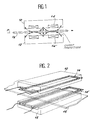
- the induction heating device comprises, in this nonlimiting exemplary embodiment, two magnetic plates 10 and 12 respectively provided with electrical coils such as 14, 14 ', these reinforcements being placed on either side of the large faces of the product 16 to be heated.
- each of the plates 10, 12 is supplied with the aid of a single-phase alternating current, the frequency of which is chosen so that the penetration depth of the currents induced in the product 16 to be heated is less than half thickness of this product.
- this characteristic makes it possible to obtain a neutral zone in which the magnetic field is zero, this neutral zone extending on either side of the central median plane P, parallel to the large faces of product 16 and which ultimately merges with this plane in which there is no current induced and, this up to the vicinity of the edges of the product 16.
- a ring distribution of the induced currents is carried out so as to obtain a heating, the distribution homogeneity of which is satisfactory.
- This ring closure of the currents induced in the large faces by the small faces of the product 16 to be heated is obtained by canceling the component of the magnetic field tangent to the small face and orthogonal to the median plane P defined above.
- this result is achieved by supplying the inductors 10-12, arranged symmetrically with respect to the median plane P, so that the magnetic fields generated are in phase opposition.
- the distribution of the induced currents and therefore the homogeneity of the heating are not influenced by the width of the product 16 as soon as the active surface of the inductor extends over a width greater than that of the product, the largest, to be heated by the device according to the invention.
- the two plates 10 and 12 are mechanically independent of each other. It follows that it is possible to adjust to any required value their respective distance from the product 16 to be heated, this device further constituting an "open" inductor which can be removed even in the presence of the product to be heated, which results in a considerable improvement in terms of efficiency and safety.
- each of the frames such as 10-12 can be provided on its outer face (see FIG. 3) with a ski system such as 18 integrated into the structure of the inductor making it possible to protect this inductor, and more particularly heat shields, possible shocks originating from surface irregularities or faults of the products 16 to be heated.
- the number of skis is chosen according to the length of the inductor.
Landscapes
- Engineering & Computer Science (AREA)
- Physics & Mathematics (AREA)
- Electromagnetism (AREA)
- Mechanical Engineering (AREA)
- General Engineering & Computer Science (AREA)
- Chemical & Material Sciences (AREA)
- Combustion & Propulsion (AREA)
- Power Engineering (AREA)
- General Induction Heating (AREA)
Abstract
Description
- La présente invention concerne un dispositif de chauffage au défilé, par induction, de produits plats notamment métalliques.
- A l'heure actuelle, le chauffage au défilé par induction de produits plats est réalisé à l'aide de bobinages qui sont disposés de façon à entourer le produit à réchauffer en créant un champ magnétique parallèle à la surface extérieure de ce produit selon la direction de défilement (flux longitudinal). Dans ces installations de chauffage par induction, les dimensions intérieures de chaque bobinage dépendent de la forme du produit et de ses éventuels défauts géométriques. Lors de la conception des bobinages, on est donc amené à tenir compte de ces impératifs et il en résulte un sur-dimensionnement intérieur du bobinage par rapport au volume à chauffer, ce qui se traduit par une faible efficacité du chauffage, une diminution du rendement électrique et par conséquent, par une augmentation de la taille des installations de chauffage par induction. Par ailleurs, dans ces installations connues, le produit est "prisonnier" du bobinage étant donné qu'il défile à l'intérieur des bobinages fixes.
- En revanche, dans ces installations, on obtient une distribution en anneau des courants induits qui enlacent le produit en déplacement continu, ce qui se traduit par un échauffement dont l'homogénéité de répartition est généralement considérée comme satisfaisante.
- Selon une autre solution connue pour le chauffage au défilé par induction de produits métalliques plats, on créé un champ magnétique perpendiculaire aux grandes faces du produit à chauffer selon la technique dite du "flux transverse en phase". Dans ce mode de mise en oeuvre, on dispose deux bobinages de part et d'autre du produit à réchauffer, en regard de chacune des faces de ce dernier, ces bobinages étant alimentés à une fréquence telle que le champ magnétique soit traversant. Dans les installations mettant en oeuvre cette technique connue, la distance entre les bobinages (qui sont mécaniquement désolidarisés l'un de l'autre) et le produit à réchauffer peut être réduite à un strict minimum, ce qui permet d'obtenir une efficacité accrue du chauffage par induction et une amélioration du rendement électrique. En outre, dans ces installations, le produit à réchauffer n'est pas prisonnier de l'inducteur, ce qui permet d'intervenir sans difficulté en cas de perturbations dans le déroulement du processus de chauffage au défilé.
- Cependant, dans ces installations connues, la distribution en boucle des courants induits ne permet généralement pas d'atteindre une homogénéité du chauffage qui soit satisfaisante.
- Compte-tenu des inconvénients des solutions selon l'état antérieur de la technique rappelé ci-dessus, la présente invention se propose d'apporter une solution originale en réalisant un dispositif de chauffage par induction conduisant à une distribution en anneau des courants induits dans le produit à chauffer, ce qui assure ainsi un échauffement de ce produit avec une homogénéité de répartition satisfaisante et à la possibilité de régler la position des bobinages de l'inducteur, par rapport au produit, ce qui améliore l'efficacité du chauffage ainsi que la sécurité.
- En conséquence, la présente invention concerne un dispositif de chauffage au défilé par induction de produits métalliques plats à l'aide de bobinages électriques prevus sur des armatures magnétiques disposés de part et d'autre des grandes faces du produit à chauffer se déplaçant de façon continue entre lesdits bobinages caractérisés en ce que les inducteurs, sont mécaniquement indépendants l'un de l'autre et ils sont disposés symétriquement par rapport au plan médian du produit et alimentés électriquement de façon que les champs magnétiques générés soient en opposition de phase conduisant à une distribution en anneau des courants induits dans le produit à réchauffer.
- Selon une caractéristique du dispositif de l'invention chacun des bobinages est alimenté en courant alternatif monophasé dont la fréquence est déterminée de manière que la profondeur de pénétration des courants induits soit inférieure à la demi-épaisseur du produit chauffé.
- D'autres caractéristiques et avantages de la présente invention ressortiront de la description faite ci-après en référence aux dessins annexés qui en illustrent un exemple de réalisation dépourvu de tout caractère limitatif. Sur les dessins :
- la figure 1 est une vue schématique en coupe axiale, verticale d'un dispositif de chauffage par induction réalisé conformément à l'invention :
- la figure 2 est une vue en perspective de ce même dispositif et ;
- la figure 3 représente une armature d'un inducteur de chauffage selon une variante de la présente invention.
- En se référant aux dessins, et plus particulièrement aux figures 1 et 2, on voit que le dispositif de chauffage par induction selon la présente invention comprend, dans cet exemple de réalisation non limitatif deux armatures magnétiques respectivement 10 et 12 pourvues de bobinages électriques tels que 14, 14', ces armatures étant placés de part et d'autre des grandes faces du produit 16 à chauffer.
- Selon l'invention, chacune des armatures 10, 12 est alimentée à l'aide d'un courant alternatif monophasé dont la fréquence est choisie de manière que la profondeur de pénétration des courants induits dans le produit 16 à chauffer soit inférieur à la demi-épaisseur de ce produit. Comme on l'a représenté sur la figure 1, cette caractéristique permet d'obtenir une zone neutre dans laquelle le champ magnétique est nul, cette zone neutre s'étendant de part et d'autre du plan médian central P, parallèle aux grandes faces du produit 16 et qui à la limite se confond avec ce plan dans lequel il n'existe aucun courant induit et, cela jusqu'au voisinage des rives du produit 16.
- Selon la présente invention, on réalise une distribution en anneau des courants induits de façon à obtenir un échauffement dont l'homogénéité de répartition est satisfaisante. Cette fermeture en anneau des courants induits dans les grandes faces par les petites faces du produit 16 à réchauffer est obtenu en annulant la composante du champ magnétique tangent à la petite face et orthogonal au plan médian P défini ci-dessus. Selon l'invention, ce résultat est atteint en alimentant les inducteurs 10-12, disposés symétriquement par rapport au plan médian P, de façon que les champs magnétiques générés soient en opposition de phase.
- On notera que grâce aux caractéristiques de la présente invention décrites ci-dessus, la distribution des courants induits et donc l'homogénéité du chauffage ne sont pas influencées par la largeur du produit 16 dès lors que la surface active de l'inducteur s'étend sur une largeur supérieure à celle du produit, le plus large, devant être chauffé par le dispositif selon l'invention.
- Dans le dispositif de chauffage par induction selon l'invention, tel que décrit ci-dessus, les deux armatures 10 et 12 sont mécaniquement indépendantes l'une de l'autre. Il en résulte qu'il est possible de régler à toute valeur requise leur distance respective par rapport au produit 16 à réchauffer, ce dispositif constituant en outre un inducteur "ouvert" qui peut être retiré même en présence du produit à chauffer, ce qui se traduit par une amélioration considérable sur le plan de l'efficacité et de la sécurité.
- Selon la présente invention, chacune des armatures telles que 10-12 peut être munie sur sa face extérieure (voir la figure 3) d'un système de ski telle que 18 intégré à la structure de l'inducteur permettant de protéger cet inducteur, et plus particulièrement les écrans thermiques, des chocs éventuels provenant des irrégularités de surface ou des défauts des produits 16 à chauffer. Le nombre des skis est choisi en fonction de la longueur de l'inducteur.
- Outre les avantages déjà mentionnés ci-dessus notamment une bonne homogénéité de la répartition de l'échauffement du produit, un bon rendement électrique, une efficacité accrue du chauffage et une meilleure sécurité, apportés par le dispositif de chauffage par induction objet de la présente invention, on peut en outre citer les avantages supplémentaires ci-après :
- puissance spécifique élevée, et
- compacité permettant l'installation du dispositif de chauffage entre les rouleaux des tables d'attente dans une installation de traitement de produits métalliques en bande.
- Il demeure bien entendu que la présente invention n'est pas limitée aux exemples de réalisation décrits et/ou représentés ici, mais qu'elle en englobe toutes les variantes.
Claims (5)
Applications Claiming Priority (2)
| Application Number | Priority Date | Filing Date | Title |
|---|---|---|---|
| FR9207741 | 1992-06-24 | ||
| FR9207741A FR2693071B1 (fr) | 1992-06-24 | 1992-06-24 | Dispositif de chauffage inductif homogene de produits plats metalliques au defile. |
Publications (2)
| Publication Number | Publication Date |
|---|---|
| EP0576352A1 true EP0576352A1 (fr) | 1993-12-29 |
| EP0576352B1 EP0576352B1 (fr) | 2001-09-19 |
Family
ID=9431135
Family Applications (1)
| Application Number | Title | Priority Date | Filing Date |
|---|---|---|---|
| EP93401605A Expired - Lifetime EP0576352B1 (fr) | 1992-06-24 | 1993-06-22 | Dispositif de chauffage inductif homogène de produits plats métalliques au défilé |
Country Status (6)
| Country | Link |
|---|---|
| US (1) | US5397877A (fr) |
| EP (1) | EP0576352B1 (fr) |
| JP (1) | JP3381966B2 (fr) |
| DE (1) | DE69330770T2 (fr) |
| ES (1) | ES2161227T3 (fr) |
| FR (1) | FR2693071B1 (fr) |
Cited By (1)
| Publication number | Priority date | Publication date | Assignee | Title |
|---|---|---|---|---|
| FR2780846A1 (fr) * | 1998-07-01 | 2000-01-07 | Electricite De France | Procede et dispositif de chauffage de bande d'acier par flux d'induction transverse |
Families Citing this family (23)
| Publication number | Priority date | Publication date | Assignee | Title |
|---|---|---|---|---|
| US6412252B1 (en) | 1996-11-15 | 2002-07-02 | Kaps-All Packaging Systems, Inc. | Slotted induction heater |
| US6747252B2 (en) * | 1996-11-15 | 2004-06-08 | Kenneth J. Herzog | Multiple head induction sealer apparatus and method |
| US6633480B1 (en) | 1997-11-07 | 2003-10-14 | Kenneth J. Herzog | Air-cooled induction foil cap sealer |
| FR2838282B1 (fr) * | 2002-04-04 | 2004-06-11 | Celes | Perfectionnements apportes aux inducteurs de chauffage, notamment de bandes metalliques |
| US6677561B1 (en) | 2002-10-21 | 2004-01-13 | Outokumpu Oyj | Coil for induction heating of a strip or another elongate metal workpiece |
| JP2006294396A (ja) * | 2005-04-11 | 2006-10-26 | Shimada Phys & Chem Ind Co Ltd | 誘導加熱装置 |
| DE102009040825A1 (de) * | 2009-09-10 | 2011-03-24 | Sms Elotherm Gmbh | Induktor und Verwendung eines solchen Induktors |
| IN2012DN05033A (fr) * | 2009-12-14 | 2015-10-02 | Nippon Steel Sumitomo Metal Corp | |
| BR112012020616B1 (pt) * | 2010-02-19 | 2020-12-08 | Nippon Steel Corporation | dispositivo de aquecimento por indução de fluxo transversal |
| JP4938155B2 (ja) * | 2010-02-19 | 2012-05-23 | 新日本製鐵株式会社 | トランスバース方式の誘導加熱装置 |
| TWI421161B (zh) * | 2011-07-13 | 2014-01-01 | Quanta Comp Inc | 高週波電磁感應加熱裝置及使用其加熱模具表面的方法 |
| US10571194B2 (en) * | 2014-01-31 | 2020-02-25 | Danieli & C. Officine Meccaniche Spa | Apparatus for heating and transferring metal materials for a melting plant, and method for melting metal materials |
| RU2674250C2 (ru) * | 2014-09-05 | 2018-12-06 | Ниппон Стил Энд Сумитомо Метал Корпорейшн | Индукционное нагревательное устройство для металлической полосы |
| CN105698525B (zh) * | 2014-11-27 | 2019-07-23 | 宝山钢铁股份有限公司 | 具有分半式平板感应线圈的感应加热炉 |
| JP6665928B2 (ja) * | 2016-03-30 | 2020-03-13 | 日本製鉄株式会社 | 誘導加熱装置および誘導加熱方法 |
| EP3520565B1 (fr) | 2016-09-27 | 2020-07-22 | Novelis, Inc. | Induction de chaleur à aimant rotatif |
| ES2816124T3 (es) | 2016-09-27 | 2021-03-31 | Novelis Inc | Calentamiento rápido de piezas iniciales de chapa metálica para estampación |
| KR102246087B1 (ko) * | 2019-11-22 | 2021-05-03 | 주식회사 다원시스 | 유도 가열 장치 |
| KR102247030B1 (ko) * | 2019-11-22 | 2021-04-30 | 주식회사 다원시스 | 유도 가열 장치 |
| FR3107635B1 (fr) * | 2020-02-24 | 2023-06-02 | Fives Celes | Dispositif de chauffage d’un produit par induction a flux transverse |
| JP7447844B2 (ja) * | 2021-02-23 | 2024-03-12 | 株式会社デンソー | 磁場発生装置およびそれを備えた磁気センサ |
| DE102023135183A1 (de) | 2023-12-14 | 2025-06-18 | Friedrich-Alexander-Universität Erlangen-Nürnberg, in Vertretung des Freistaates Bayern | Vorrichtung und Verfahren zur Herstellung eines Folienverbunds |
| SE547407C2 (en) * | 2024-01-19 | 2025-09-16 | Frogner Innovation Ab | High power density induction heater |
Citations (5)
| Publication number | Priority date | Publication date | Assignee | Title |
|---|---|---|---|---|
| FR1034097A (fr) * | 1950-03-18 | 1953-07-17 | Asea Ab | Four à induction à haute fréquence |
| DE903847C (de) * | 1943-01-12 | 1954-02-11 | Deutsche Edelstahlwerke Ag | Vorrichtung zum einseitigen elektro-induktiven Erhitzen von Werkstuecken |
| FR1235881A (fr) * | 1958-09-19 | 1960-07-08 | Deutsche Edelstahlwerke Ag | Procédé et dispositif pour assurer le chauffage inductif de pièces métalliques par un champ transversal |
| FR2495752A1 (fr) * | 1980-12-10 | 1982-06-11 | Siderurgie Fse Inst Rech | Dispositif de chauffage electrique par induction de produits electroconducteurs solides |
| US4678883A (en) * | 1985-08-09 | 1987-07-07 | Sumitomo Heavy Industries, Ltd. | Electromagnetic-induction heater with magnetic field control |
Family Cites Families (9)
| Publication number | Priority date | Publication date | Assignee | Title |
|---|---|---|---|---|
| US2448009A (en) * | 1944-02-05 | 1948-08-31 | Westinghouse Electric Corp | Inductive heating of longitudinally moving metal strip |
| US2902572A (en) * | 1957-03-05 | 1959-09-01 | Penn Induction Company | Induction heating of metal strip |
| NL243545A (fr) * | 1958-09-19 | 1900-01-01 | ||
| US4321444A (en) | 1975-03-04 | 1982-03-23 | Davies Evan J | Induction heating apparatus |
| US4122321A (en) | 1977-02-16 | 1978-10-24 | Park-Ohio Industries, Inc. | Induction heating furnace |
| FR2509562A1 (fr) * | 1981-07-10 | 1983-01-14 | Cem Comp Electro Mec | Procede et dispositif de chauffage homogene par induction electromagnetique a flux transversal de produits plats, conducteurs et amagnetiques |
| JPS6298588A (ja) * | 1985-10-25 | 1987-05-08 | 日本軽金属株式会社 | 横磁束型電磁誘導加熱装置 |
| GB8721663D0 (en) * | 1987-09-15 | 1987-10-21 | Electricity Council | Induction heating apparatus |
| US5034586A (en) * | 1990-05-03 | 1991-07-23 | Ajax Magnethermic Corporation | Induction heating assembly including an interposed closed conductive loop for suppression of intercoil coupling |
-
1992
- 1992-06-24 FR FR9207741A patent/FR2693071B1/fr not_active Expired - Fee Related
-
1993
- 1993-06-22 EP EP93401605A patent/EP0576352B1/fr not_active Expired - Lifetime
- 1993-06-22 ES ES93401605T patent/ES2161227T3/es not_active Expired - Lifetime
- 1993-06-22 DE DE69330770T patent/DE69330770T2/de not_active Expired - Fee Related
- 1993-06-24 US US08/080,831 patent/US5397877A/en not_active Expired - Fee Related
- 1993-06-24 JP JP15331793A patent/JP3381966B2/ja not_active Expired - Fee Related
Patent Citations (5)
| Publication number | Priority date | Publication date | Assignee | Title |
|---|---|---|---|---|
| DE903847C (de) * | 1943-01-12 | 1954-02-11 | Deutsche Edelstahlwerke Ag | Vorrichtung zum einseitigen elektro-induktiven Erhitzen von Werkstuecken |
| FR1034097A (fr) * | 1950-03-18 | 1953-07-17 | Asea Ab | Four à induction à haute fréquence |
| FR1235881A (fr) * | 1958-09-19 | 1960-07-08 | Deutsche Edelstahlwerke Ag | Procédé et dispositif pour assurer le chauffage inductif de pièces métalliques par un champ transversal |
| FR2495752A1 (fr) * | 1980-12-10 | 1982-06-11 | Siderurgie Fse Inst Rech | Dispositif de chauffage electrique par induction de produits electroconducteurs solides |
| US4678883A (en) * | 1985-08-09 | 1987-07-07 | Sumitomo Heavy Industries, Ltd. | Electromagnetic-induction heater with magnetic field control |
Cited By (1)
| Publication number | Priority date | Publication date | Assignee | Title |
|---|---|---|---|---|
| FR2780846A1 (fr) * | 1998-07-01 | 2000-01-07 | Electricite De France | Procede et dispositif de chauffage de bande d'acier par flux d'induction transverse |
Also Published As
| Publication number | Publication date |
|---|---|
| JP3381966B2 (ja) | 2003-03-04 |
| JPH0636867A (ja) | 1994-02-10 |
| ES2161227T3 (es) | 2001-12-01 |
| EP0576352B1 (fr) | 2001-09-19 |
| FR2693071B1 (fr) | 2000-03-31 |
| DE69330770T2 (de) | 2002-05-29 |
| US5397877A (en) | 1995-03-14 |
| DE69330770D1 (de) | 2001-10-25 |
| FR2693071A1 (fr) | 1993-12-31 |
Similar Documents
| Publication | Publication Date | Title |
|---|---|---|
| EP0576352B1 (fr) | Dispositif de chauffage inductif homogène de produits plats métalliques au défilé | |
| EP1148762B1 (fr) | Dispositif de chauffage par induction à flux transverse à circuit magnétique de largeur variable | |
| EP0170556B1 (fr) | Dispositif à induction électromagnétique pour le chauffage d'éléments métalliques | |
| CA2312876C (fr) | Equipement de freinage electromagnetique d'un metal en fusion dans une installation de coulee continue | |
| FR2576409A1 (fr) | Debitmetre electromagnetique | |
| FR2661849A1 (fr) | Procede et dispositifs de rechauffage par induction au defile d'un produit metallurgique de forme allongee. | |
| CH353071A (fr) | Machine électrique tournante | |
| EP0081400B1 (fr) | Dispositif de chauffage par induction magnétique de produits métalliques rectangulaires plats défilant dans le sens de leur longueur | |
| EP0005676A2 (fr) | Procédé de brassage électromagnétique de billettes ou blooms coulés en continu | |
| EP0053060B2 (fr) | Inducteur à champ glissant et à flux orienté pour rouleau-brasseur de coulée continue de brames | |
| EP0197482A2 (fr) | Dispositif de brassage de métal en fusion dans une installation de coulée continue | |
| FR2801523A1 (fr) | Procede de coulee continue des metaux du type utilisant des champs electromagnetiques, et lingotiere et installation de coulee pour sa mise en oeuvre | |
| CA2529384A1 (fr) | Installation de coulee continue pour une mise en rotation electro-magnetique du metal liquide en transit dans la busette de coulee | |
| EP1259343B1 (fr) | Equipement pour alimenter en metal en fusion une lingotiere de coulee continue et son procede d'utilisation | |
| EP0266470B1 (fr) | Inducteur et dispositif de réchauffage inductif de rives d'un produit métallurgique | |
| EP0090676B1 (fr) | Procédé et dispositifs de réglage de la puissance moyenne de chauffage induite dans un produit plat conducteur maintenu électromagnétiquement en position sans contact | |
| FR2702402A1 (fr) | Procédé et dispositif pour réaliser l'étanchéité latérale lors de la coulée de feuillards ayant des dimensions proches des dimensions finales. | |
| FR2793066A1 (fr) | Procede et dispositif pour la demagnetisation de produits de faible epaisseur | |
| WO2003086020A2 (fr) | Perfectionnements apportes aux inducteurs de chauffage, notamment de bandes metalliques | |
| EP0129160B1 (fr) | Dispositif de chauffage de produits métalliques au défilé par induction | |
| EP0277889B1 (fr) | Procédé de réglage au niveau de la ligne de contact de la surface libre du métal avec la lingotière dans une coulée verticale de produits de section quelconque | |
| FR3024584A1 (fr) | Composant magnetique comportant un moyen de conduction de la chaleur | |
| EP0690663A1 (fr) | Inducteur de chauffage par induction de bandes métalliques | |
| FR2783728A1 (fr) | Installation pour le chauffage de produits metallurgiques comportant des dispositifs par induction, positionnes en quinconce | |
| FR2521796A1 (fr) | Moteur electrique asynchrone lineaire |
Legal Events
| Date | Code | Title | Description |
|---|---|---|---|
| PUAI | Public reference made under article 153(3) epc to a published international application that has entered the european phase |
Free format text: ORIGINAL CODE: 0009012 |
|
| AK | Designated contracting states |
Kind code of ref document: A1 Designated state(s): BE CH DE ES GB IT LI NL SE |
|
| 17P | Request for examination filed |
Effective date: 19940610 |
|
| 17Q | First examination report despatched |
Effective date: 19960903 |
|
| GRAG | Despatch of communication of intention to grant |
Free format text: ORIGINAL CODE: EPIDOS AGRA |
|
| GRAG | Despatch of communication of intention to grant |
Free format text: ORIGINAL CODE: EPIDOS AGRA |
|
| GRAH | Despatch of communication of intention to grant a patent |
Free format text: ORIGINAL CODE: EPIDOS IGRA |
|
| GRAH | Despatch of communication of intention to grant a patent |
Free format text: ORIGINAL CODE: EPIDOS IGRA |
|
| GRAA | (expected) grant |
Free format text: ORIGINAL CODE: 0009210 |
|
| ITF | It: translation for a ep patent filed | ||
| AK | Designated contracting states |
Kind code of ref document: B1 Designated state(s): BE CH DE ES GB IT LI NL SE |
|
| REG | Reference to a national code |
Ref country code: CH Ref legal event code: EP |
|
| GBT | Gb: translation of ep patent filed (gb section 77(6)(a)/1977) |
Effective date: 20010919 |
|
| REF | Corresponds to: |
Ref document number: 69330770 Country of ref document: DE Date of ref document: 20011025 |
|
| REG | Reference to a national code |
Ref country code: ES Ref legal event code: FG2A Ref document number: 2161227 Country of ref document: ES Kind code of ref document: T3 |
|
| REG | Reference to a national code |
Ref country code: GB Ref legal event code: IF02 |
|
| RAP2 | Party data changed (patent owner data changed or rights of a patent transferred) |
Owner name: CELES |
|
| NLT2 | Nl: modifications (of names), taken from the european patent patent bulletin |
Owner name: CELES |
|
| PLBE | No opposition filed within time limit |
Free format text: ORIGINAL CODE: 0009261 |
|
| STAA | Information on the status of an ep patent application or granted ep patent |
Free format text: STATUS: NO OPPOSITION FILED WITHIN TIME LIMIT |
|
| 26N | No opposition filed | ||
| PGFP | Annual fee paid to national office [announced via postgrant information from national office to epo] |
Ref country code: GB Payment date: 20030624 Year of fee payment: 11 |
|
| PGFP | Annual fee paid to national office [announced via postgrant information from national office to epo] |
Ref country code: BE Payment date: 20030625 Year of fee payment: 11 |
|
| PGFP | Annual fee paid to national office [announced via postgrant information from national office to epo] |
Ref country code: SE Payment date: 20030626 Year of fee payment: 11 |
|
| PGFP | Annual fee paid to national office [announced via postgrant information from national office to epo] |
Ref country code: ES Payment date: 20030627 Year of fee payment: 11 |
|
| PGFP | Annual fee paid to national office [announced via postgrant information from national office to epo] |
Ref country code: NL Payment date: 20030630 Year of fee payment: 11 |
|
| PGFP | Annual fee paid to national office [announced via postgrant information from national office to epo] |
Ref country code: CH Payment date: 20030718 Year of fee payment: 11 |
|
| PGFP | Annual fee paid to national office [announced via postgrant information from national office to epo] |
Ref country code: DE Payment date: 20030721 Year of fee payment: 11 |
|
| PG25 | Lapsed in a contracting state [announced via postgrant information from national office to epo] |
Ref country code: GB Free format text: LAPSE BECAUSE OF NON-PAYMENT OF DUE FEES Effective date: 20040622 |
|
| PG25 | Lapsed in a contracting state [announced via postgrant information from national office to epo] |
Ref country code: SE Free format text: LAPSE BECAUSE OF NON-PAYMENT OF DUE FEES Effective date: 20040623 Ref country code: ES Free format text: LAPSE BECAUSE OF NON-PAYMENT OF DUE FEES Effective date: 20040623 |
|
| PG25 | Lapsed in a contracting state [announced via postgrant information from national office to epo] |
Ref country code: LI Free format text: LAPSE BECAUSE OF NON-PAYMENT OF DUE FEES Effective date: 20040630 Ref country code: CH Free format text: LAPSE BECAUSE OF NON-PAYMENT OF DUE FEES Effective date: 20040630 Ref country code: BE Free format text: LAPSE BECAUSE OF NON-PAYMENT OF DUE FEES Effective date: 20040630 |
|
| BERE | Be: lapsed |
Owner name: SOC. *CELES Effective date: 20040630 |
|
| PG25 | Lapsed in a contracting state [announced via postgrant information from national office to epo] |
Ref country code: NL Free format text: LAPSE BECAUSE OF NON-PAYMENT OF DUE FEES Effective date: 20050101 Ref country code: DE Free format text: LAPSE BECAUSE OF NON-PAYMENT OF DUE FEES Effective date: 20050101 |
|
| EUG | Se: european patent has lapsed | ||
| EUG | Se: european patent has lapsed | ||
| GBPC | Gb: european patent ceased through non-payment of renewal fee |
Effective date: 20040622 |
|
| REG | Reference to a national code |
Ref country code: CH Ref legal event code: PL |
|
| NLV4 | Nl: lapsed or anulled due to non-payment of the annual fee |
Effective date: 20050101 |
|
| PG25 | Lapsed in a contracting state [announced via postgrant information from national office to epo] |
Ref country code: IT Free format text: LAPSE BECAUSE OF NON-PAYMENT OF DUE FEES;WARNING: LAPSES OF ITALIAN PATENTS WITH EFFECTIVE DATE BEFORE 2007 MAY HAVE OCCURRED AT ANY TIME BEFORE 2007. THE CORRECT EFFECTIVE DATE MAY BE DIFFERENT FROM THE ONE RECORDED. Effective date: 20050622 |
|
| REG | Reference to a national code |
Ref country code: ES Ref legal event code: FD2A Effective date: 20040623 |