EP0575795A1 - Wandung aus wenigstens zwei Wandungsteilen - Google Patents
Wandung aus wenigstens zwei Wandungsteilen Download PDFInfo
- Publication number
- EP0575795A1 EP0575795A1 EP93109006A EP93109006A EP0575795A1 EP 0575795 A1 EP0575795 A1 EP 0575795A1 EP 93109006 A EP93109006 A EP 93109006A EP 93109006 A EP93109006 A EP 93109006A EP 0575795 A1 EP0575795 A1 EP 0575795A1
- Authority
- EP
- European Patent Office
- Prior art keywords
- wall
- wall parts
- weld seam
- parts
- weld
- Prior art date
- Legal status (The legal status is an assumption and is not a legal conclusion. Google has not performed a legal analysis and makes no representation as to the accuracy of the status listed.)
- Withdrawn
Links
- 238000003466 welding Methods 0.000 claims description 8
- 238000004519 manufacturing process Methods 0.000 description 4
- 238000010411 cooking Methods 0.000 description 3
- 230000017525 heat dissipation Effects 0.000 description 2
- 125000006850 spacer group Chemical group 0.000 description 2
- RYGMFSIKBFXOCR-UHFFFAOYSA-N Copper Chemical compound [Cu] RYGMFSIKBFXOCR-UHFFFAOYSA-N 0.000 description 1
- 238000013459 approach Methods 0.000 description 1
- 230000015572 biosynthetic process Effects 0.000 description 1
- 239000003795 chemical substances by application Substances 0.000 description 1
- 229910052802 copper Inorganic materials 0.000 description 1
- 239000010949 copper Substances 0.000 description 1
- 230000001419 dependent effect Effects 0.000 description 1
- 238000009776 industrial production Methods 0.000 description 1
- 230000000717 retained effect Effects 0.000 description 1
- 230000000087 stabilizing effect Effects 0.000 description 1
- 230000008646 thermal stress Effects 0.000 description 1
Images


Classifications
-
- A—HUMAN NECESSITIES
- A47—FURNITURE; DOMESTIC ARTICLES OR APPLIANCES; COFFEE MILLS; SPICE MILLS; SUCTION CLEANERS IN GENERAL
- A47J—KITCHEN EQUIPMENT; COFFEE MILLS; SPICE MILLS; APPARATUS FOR MAKING BEVERAGES
- A47J27/00—Cooking-vessels
- A47J27/002—Construction of cooking-vessels; Methods or processes of manufacturing specially adapted for cooking-vessels
-
- B—PERFORMING OPERATIONS; TRANSPORTING
- B23—MACHINE TOOLS; METAL-WORKING NOT OTHERWISE PROVIDED FOR
- B23K—SOLDERING OR UNSOLDERING; WELDING; CLADDING OR PLATING BY SOLDERING OR WELDING; CUTTING BY APPLYING HEAT LOCALLY, e.g. FLAME CUTTING; WORKING BY LASER BEAM
- B23K33/00—Specially-profiled edge portions of workpieces for making soldering or welding connections; Filling the seams formed thereby
- B23K33/004—Filling of continuous seams
Definitions
- the invention relates to a wall made of at least two wall parts, which are to be connected to one another essentially without a joint, a weld seam or the like being provided as a connection on an abutting edge of the wall parts and wherein an attachment surface for the other wall part is formed on at least one of the wall parts.
- a wall has also become known in which the wall parts are placed against one another at attachment surfaces which are provided in the plane of the joint between the wall parts and are then welded together again at the abutting edge. Although the manufacturing effort for this wall is significantly lower, tilt stability in the area of the joint or weld seam, in particular, cannot be guaranteed reliably, since the processed sheets are generally thin sheets.
- the attachment surface extends at least in the area of the weld seam essentially parallel to a tangential plane to the wall parts which contain the abutting edge. It is not only possible to align the wall parts with each other in the simplest way, since the vertical contact of the wall part results in a self-centering, so to speak, and the thermal stresses that may occur during welding are effectively neutralized, and necessary ones may also be necessary Devices are attached to one of the wall parts, they are then in the correct position relative to the other wall part without further measures. A suitable design of the attachment surface can create optimal attachment options for such devices. In addition, the stability, in particular the tilting stability, is provided.
- a weld seam or the like being provided as a connection on an abutting edge of the wall parts and with an attachment surface for the other on at least one of the wall parts
- Wall part is formed, which extends at least in the area of the weld seam substantially perpendicular to a tangent plane to the wall parts, which contains the abutting edge, spaced from the abutting edge, a further weld seam is provided on, for example, two of the attachment surfaces.
- This weld seam preferably a roll seam in the case of two flanges, also stabilizes the wall, while the aforementioned advantages are retained.
- the joint between the wall parts is also hygienically closed by a weld.
- the attachment of devices and means is further simplified if at least one of the wall parts has a flange bent from the wall part. Often the flanges alone will ensure sufficient heat dissipation.
- the flange extends substantially perpendicular to the respective wall part in the area of the weld seam.
- the attachment surface is further preferably provided on the flange.
- At least one of the flanges can be set at an angle to the respective wall part, this angle advantageously being about 135, which favors the optimal formation of a weld seam in the connection area of the flanges, which corresponds to the abutting edge, and what also offers visually appealing options for the Design of the seam leads.
- welds can be provided not only in the connection area of the flanges, but also in their contact area, the latter then contributing to increased stability of the wall or also significantly supporting it, while the seam in the connection area then mainly serves to close the joint there.
- This seam can be formed by laser welding.
- the stabilizing weld seam on the attachment surfaces can also be formed at a distance from the abutting edge by laser welding, the flanges being optionally cut at the same time.
- the wall shown in Fig. 1 consists of two wall parts, a jacket 1 and an adjoining bottom (or cover) 2, which is shown here curved.
- Sheath 1 and bottom 2 meet at an abutting edge 3 and are connected to one another in this area, if they are precisely aligned, by a weld 4.
- the surfaces of the jacket 1, bottom 2 and weld 4 facing to the same side are aligned with one another, so that hygienic requirements are met by the smooth surface of the wall.
- the wall parts once aligned would tip during welding if they were not secured against them. According to the state of the art, as shown here, this is only possible with great effort.
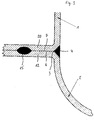
- Fig. 2 shows a wall according to a first embodiment of the invention.
- One of the wall parts, here the jacket 1, is designed as in the prior art.
- a step 11 is provided on the second wall part 2 at its upper end in the figure which is formed with a flange 10 bent with respect to the wall, which extends from the wall part beyond the step 11.
- the jacket 1 lies on a shoulder surface 5, which is formed by a side surface of the flange 10.
- the lower boundary line of the attachment surface 5 forms the abutting edge 3 for the jacket 1 as shown in FIG. 1.
- the weld 4 applied between the jacket 1 and the wall surface 2 is aligned again, as already described in connection with FIG. 1, so that again there is a smooth wall surface.
- the flange 10 can carry a tensioning device or take up heat-dissipating means if it is not itself sufficient for heat dissipation.
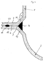
- both wall surfaces 1, 2 have a flange 20, 12, with the flanges being placed one on top of the other for welding, correspondingly aligned.
- the superimposed surfaces then each form the attachment surfaces 6, 7, which are delimited in the direction of the wall parts 1, 2 by the abutting edge 3.
- the load-bearing weld seam is designed here as a connection between the flanges 20, 12, for example as a roll seam 15, while the weld seam 4, in the usual configuration or also formed by laser welding, serves to joint the wall parts 1, 2 or the flanges 20 To close 12.
- the flanges 20, 12 are made on the wall parts 1, 2 via intermediate pieces 21, 13, the intermediate pieces 21, 13 each at an angle o of approximately 135 to the wall parts 1, 2 and to the straight sections of the Flanges 20, 12 lie.
- the intermediate pieces 21, 13 lie against each other at the abutting edge 3, this is again the limitation for the attachment surfaces 6, 7 of the flanges 12, 20.
- the load-bearing connection is again a roller seam 15 in the area of the flanges 12, 20, while the weld seam 4 is the Fung closes between the two wall parts, but it does not fill the entire space between the intermediate pieces 21, 13.
Landscapes
- Engineering & Computer Science (AREA)
- Mechanical Engineering (AREA)
- Manufacturing & Machinery (AREA)
- Food Science & Technology (AREA)
- Laser Beam Processing (AREA)
- Standing Axle, Rod, Or Tube Structures Coupled By Welding, Adhesion, Or Deposition (AREA)
- Commercial Cooking Devices (AREA)
Applications Claiming Priority (2)
| Application Number | Priority Date | Filing Date | Title |
|---|---|---|---|
| DE4220340 | 1992-06-23 | ||
| DE19924220340 DE4220340C1 (enExample) | 1992-06-23 | 1992-06-23 |
Publications (1)
| Publication Number | Publication Date |
|---|---|
| EP0575795A1 true EP0575795A1 (de) | 1993-12-29 |
Family
ID=6461516
Family Applications (1)
| Application Number | Title | Priority Date | Filing Date |
|---|---|---|---|
| EP93109006A Withdrawn EP0575795A1 (de) | 1992-06-23 | 1993-06-04 | Wandung aus wenigstens zwei Wandungsteilen |
Country Status (3)
| Country | Link |
|---|---|
| EP (1) | EP0575795A1 (enExample) |
| JP (1) | JPH06109010A (enExample) |
| DE (1) | DE4220340C1 (enExample) |
Families Citing this family (3)
| Publication number | Priority date | Publication date | Assignee | Title |
|---|---|---|---|---|
| DE19501611A1 (de) * | 1995-01-20 | 1996-07-25 | Bayerische Motoren Werke Ag | Bauteil |
| DE102007008772A1 (de) | 2006-11-30 | 2008-06-05 | BSH Bosch und Siemens Hausgeräte GmbH | Hausgerätewandungsanordnung und Verfahren zur Befestigung von Wandungsteilen bei einem Hausgerät |
| DE102009026037B4 (de) | 2009-06-25 | 2012-03-08 | Lechmetall Landsberg Gmbh Edelstahlerzeugnisse | Verfahren zum Verbinden von drei Metallwänden, insbesondere zum Herstellen eines Gehäuses und Verwendung dieses Verfahrens für ein Gehäuse eines Gargeräts |
Citations (4)
| Publication number | Priority date | Publication date | Assignee | Title |
|---|---|---|---|---|
| US1859632A (en) * | 1930-10-21 | 1932-05-24 | Pfandler Co | Thin metal tank and method of making the same |
| US2237535A (en) * | 1938-12-09 | 1941-04-08 | Gordon M Evans | Method of making welded connections for sheet metal articles |
| DE705439C (de) * | 1939-01-19 | 1941-04-28 | Paolo Ribi Dr Ing | Kugelzonenbehaelter |
| DE1806842A1 (de) * | 1968-11-04 | 1970-05-27 | Wilhelm Schwiese | Verfahren und Vorrichtung,um Giesserei-Altsande zu regenerieren |
Family Cites Families (3)
| Publication number | Priority date | Publication date | Assignee | Title |
|---|---|---|---|---|
| US2339554A (en) * | 1941-12-02 | 1944-01-18 | Firestone Tire & Rubber Co | Container |
| DE2730826C1 (de) * | 1977-07-08 | 1985-10-10 | Thyssen Industrie Ag Maschinenbau, 5810 Witten | Verfahren zum Schweissen von aus hochhartem bzw.aus hochverguetetem Panzerstahl bestehenden Koerpern,insbesondere fuer gegen das Eindringen von Geschossen,Flugkoerpern,Splittern o.dgl. zu panzernde Objekte und nach diesem Verfahren hergestellte Schweisskonstruktion |
| US4513906A (en) * | 1983-10-19 | 1985-04-30 | Chang Yi M | Liquid tank weld cavitation protection |
-
1992
- 1992-06-23 DE DE19924220340 patent/DE4220340C1/de not_active Expired - Lifetime
-
1993
- 1993-06-04 EP EP93109006A patent/EP0575795A1/de not_active Withdrawn
- 1993-06-23 JP JP15182793A patent/JPH06109010A/ja active Pending
Patent Citations (4)
| Publication number | Priority date | Publication date | Assignee | Title |
|---|---|---|---|---|
| US1859632A (en) * | 1930-10-21 | 1932-05-24 | Pfandler Co | Thin metal tank and method of making the same |
| US2237535A (en) * | 1938-12-09 | 1941-04-08 | Gordon M Evans | Method of making welded connections for sheet metal articles |
| DE705439C (de) * | 1939-01-19 | 1941-04-28 | Paolo Ribi Dr Ing | Kugelzonenbehaelter |
| DE1806842A1 (de) * | 1968-11-04 | 1970-05-27 | Wilhelm Schwiese | Verfahren und Vorrichtung,um Giesserei-Altsande zu regenerieren |
Also Published As
| Publication number | Publication date |
|---|---|
| DE4220340C1 (enExample) | 1993-09-23 |
| JPH06109010A (ja) | 1994-04-19 |
Similar Documents
| Publication | Publication Date | Title |
|---|---|---|
| EP0939986B1 (de) | Schaltschrank mit einem rahmengestell | |
| EP1479842A1 (de) | Hohlprofil | |
| CH663336A5 (de) | Kasten. | |
| DE3233048C2 (enExample) | ||
| EP0395995A2 (de) | Verfahren zum Verschweissen von Profilen, insbesondere Kunststoffprofilen | |
| EP1931494B1 (de) | Verbindungselement | |
| EP0575795A1 (de) | Wandung aus wenigstens zwei Wandungsteilen | |
| EP0340554A2 (de) | Behälter mit einem in dessen Oberboden eingebrachten, von einer Siegelvorrichtung überfangenen Verschluss | |
| EP0520206A1 (de) | Messer mit am Kropf stumpf angeschweisstem Erl | |
| DE19753653A1 (de) | Stahlblechtür | |
| EP0081615B1 (de) | Verfahren zur Herstellung einer Schweissverbindung sowie Zwischenteil zu dessen Durchführung | |
| EP0104325A1 (de) | Verfahren zum Schweissen innen plattierter zylindrischer Werkstücke | |
| EP1797987B1 (de) | Bimetallisches Verbindungselement | |
| DE69517964T2 (de) | Rahmen | |
| DE2320211C3 (de) | Fertigbauteil für einen Schacht, insbesondere Müllabwurfschacht, aus einem mehrschichtigen Flachmaterial sowie Verfahren zur Herstellung des Fertigbauteils und von Zuschnitten hierfür | |
| WO1999062669A1 (de) | Verfahren zur bildung eines blechverbundes sowie vorrichtung und satz von blechabschnitten dazu | |
| EP0064712A1 (de) | Kühlcontainer | |
| DE4221752A1 (de) | Bauplatte | |
| EP0042146B1 (de) | Löt-oder Schweissverbindung von Profilen und Verfahren zu ihrer Herstellung | |
| DE3225930C2 (de) | Druckbehälter | |
| EP2708303A1 (de) | Verfahren zur Herstellung einer Innenraumschale eines Gärschranks durch Stossschweissen sowie Gärschrank mit geschweisster Innenraumschale | |
| DE4140958A1 (de) | Wischarm, insbesondere zur reinigung von scheiben an kraftfahrzeugen | |
| EP0813279B1 (de) | Als Blechformteil hergestellte Kopfplatte | |
| DE19715453C2 (de) | Dünnwandiges Gefäß | |
| DE102018132219B4 (de) | Batteriegehäuse mit einer aus Rahmenstrukturteilen zusammengesetzten Rahmenstruktur |
Legal Events
| Date | Code | Title | Description |
|---|---|---|---|
| PUAI | Public reference made under article 153(3) epc to a published international application that has entered the european phase |
Free format text: ORIGINAL CODE: 0009012 |
|
| AK | Designated contracting states |
Kind code of ref document: A1 Designated state(s): AT BE CH DE DK ES FR GB GR IE IT LI LU NL PT SE |
|
| 17P | Request for examination filed |
Effective date: 19940531 |
|
| 17Q | First examination report despatched |
Effective date: 19950118 |
|
| STAA | Information on the status of an ep patent application or granted ep patent |
Free format text: STATUS: THE APPLICATION IS DEEMED TO BE WITHDRAWN |
|
| 18D | Application deemed to be withdrawn |
Effective date: 19950530 |