EP0574089A2 - A laser sensor device - Google Patents
A laser sensor device Download PDFInfo
- Publication number
- EP0574089A2 EP0574089A2 EP93201643A EP93201643A EP0574089A2 EP 0574089 A2 EP0574089 A2 EP 0574089A2 EP 93201643 A EP93201643 A EP 93201643A EP 93201643 A EP93201643 A EP 93201643A EP 0574089 A2 EP0574089 A2 EP 0574089A2
- Authority
- EP
- European Patent Office
- Prior art keywords
- laser
- sensor device
- laser sensor
- teat
- housing
- Prior art date
- Legal status (The legal status is an assumption and is not a legal conclusion. Google has not performed a legal analysis and makes no representation as to the accuracy of the status listed.)
- Withdrawn
Links
Images


Classifications
-
- G—PHYSICS
- G01—MEASURING; TESTING
- G01S—RADIO DIRECTION-FINDING; RADIO NAVIGATION; DETERMINING DISTANCE OR VELOCITY BY USE OF RADIO WAVES; LOCATING OR PRESENCE-DETECTING BY USE OF THE REFLECTION OR RERADIATION OF RADIO WAVES; ANALOGOUS ARRANGEMENTS USING OTHER WAVES
- G01S17/00—Systems using the reflection or reradiation of electromagnetic waves other than radio waves, e.g. lidar systems
- G01S17/88—Lidar systems specially adapted for specific applications
-
- A—HUMAN NECESSITIES
- A01—AGRICULTURE; FORESTRY; ANIMAL HUSBANDRY; HUNTING; TRAPPING; FISHING
- A01J—MANUFACTURE OF DAIRY PRODUCTS
- A01J5/00—Milking machines or devices
- A01J5/017—Automatic attaching or detaching of clusters
- A01J5/0175—Attaching of clusters
-
- G—PHYSICS
- G01—MEASURING; TESTING
- G01S—RADIO DIRECTION-FINDING; RADIO NAVIGATION; DETERMINING DISTANCE OR VELOCITY BY USE OF RADIO WAVES; LOCATING OR PRESENCE-DETECTING BY USE OF THE REFLECTION OR RERADIATION OF RADIO WAVES; ANALOGOUS ARRANGEMENTS USING OTHER WAVES
- G01S17/00—Systems using the reflection or reradiation of electromagnetic waves other than radio waves, e.g. lidar systems
- G01S17/02—Systems using the reflection of electromagnetic waves other than radio waves
- G01S17/04—Systems determining the presence of a target
-
- G—PHYSICS
- G01—MEASURING; TESTING
- G01S—RADIO DIRECTION-FINDING; RADIO NAVIGATION; DETERMINING DISTANCE OR VELOCITY BY USE OF RADIO WAVES; LOCATING OR PRESENCE-DETECTING BY USE OF THE REFLECTION OR RERADIATION OF RADIO WAVES; ANALOGOUS ARRANGEMENTS USING OTHER WAVES
- G01S17/00—Systems using the reflection or reradiation of electromagnetic waves other than radio waves, e.g. lidar systems
- G01S17/02—Systems using the reflection of electromagnetic waves other than radio waves
- G01S17/06—Systems determining position data of a target
- G01S17/42—Simultaneous measurement of distance and other co-ordinates
-
- G—PHYSICS
- G01—MEASURING; TESTING
- G01S—RADIO DIRECTION-FINDING; RADIO NAVIGATION; DETERMINING DISTANCE OR VELOCITY BY USE OF RADIO WAVES; LOCATING OR PRESENCE-DETECTING BY USE OF THE REFLECTION OR RERADIATION OF RADIO WAVES; ANALOGOUS ARRANGEMENTS USING OTHER WAVES
- G01S3/00—Direction-finders for determining the direction from which infrasonic, sonic, ultrasonic, or electromagnetic waves, or particle emission, not having a directional significance, are being received
- G01S3/78—Direction-finders for determining the direction from which infrasonic, sonic, ultrasonic, or electromagnetic waves, or particle emission, not having a directional significance, are being received using electromagnetic waves other than radio waves
- G01S3/782—Systems for determining direction or deviation from predetermined direction
- G01S3/789—Systems for determining direction or deviation from predetermined direction using rotating or oscillating beam systems, e.g. using mirrors, prisms
-
- G—PHYSICS
- G01—MEASURING; TESTING
- G01S—RADIO DIRECTION-FINDING; RADIO NAVIGATION; DETERMINING DISTANCE OR VELOCITY BY USE OF RADIO WAVES; LOCATING OR PRESENCE-DETECTING BY USE OF THE REFLECTION OR RERADIATION OF RADIO WAVES; ANALOGOUS ARRANGEMENTS USING OTHER WAVES
- G01S7/00—Details of systems according to groups G01S13/00, G01S15/00, G01S17/00
- G01S7/48—Details of systems according to groups G01S13/00, G01S15/00, G01S17/00 of systems according to group G01S17/00
- G01S7/481—Constructional features, e.g. arrangements of optical elements
- G01S7/4811—Constructional features, e.g. arrangements of optical elements common to transmitter and receiver
- G01S7/4813—Housing arrangements
-
- G—PHYSICS
- G01—MEASURING; TESTING
- G01S—RADIO DIRECTION-FINDING; RADIO NAVIGATION; DETERMINING DISTANCE OR VELOCITY BY USE OF RADIO WAVES; LOCATING OR PRESENCE-DETECTING BY USE OF THE REFLECTION OR RERADIATION OF RADIO WAVES; ANALOGOUS ARRANGEMENTS USING OTHER WAVES
- G01S7/00—Details of systems according to groups G01S13/00, G01S15/00, G01S17/00
- G01S7/48—Details of systems according to groups G01S13/00, G01S15/00, G01S17/00 of systems according to group G01S17/00
- G01S7/481—Constructional features, e.g. arrangements of optical elements
- G01S7/4817—Constructional features, e.g. arrangements of optical elements relating to scanning
Definitions
- the present invention relates to a laser sensor device for measuring the distance between the sensor and an object, which device comprises a laser accommodated in a housing, the laser transmitting to the object a beam through a window in the housing, whereby a fraction of the beam radiation dispersed by and/or reflected by the object, passes a lens, which is accommodated in the housing, and is detected by means of a receiver element.
- a laser sensor device as described above is generally known, e.g. as a laser distance sensor.
- the invention has for its object to provide an improved laser sensor device. According to the inventions this is achieved in that the housing is provided with a reflecting element for guiding the radiation dispersed by and/or reflected by the object to the receiver element. By means of the reflecting element it is possible to place the receiver element on different locations in the housing.
- the laser, the reflecting element, the lens and the receiver element are arranged in said order and at some distance from each other on an imaginary line, in the housing.
- the beam transmitted by the laser and the imaginary line meet at an angle of 90°.
- the reflecting element is arranged at an angle of approximately 45° with the beam transmitted by the laser.
- the housing is constituted by a cilindrical sleeve, whereby the laser-transparant window is provided at one end of the sleeve.
- the above described laser sensor device is, in accordance with the invention, especially suitable to be used in a milking robot.
- the laser sensor device is arranged on a robot arm, adapted to carry near its end one or more teat cups and coupling means for applying each teat cup to a relevant teat of an animal's udder, after the position of said teat is determined by means of the laser sensor device. Due to the cilindrical housing, the tracking with the scanning beam of the laser takes place just above the teat cups.
- the robot arm according to the invention is shown; this robot arm is arranged at the side of a milking parlour. Once an animal to be milked has arrived in the milking parlour and has been positioned appropriately therein, the robot arm is moved, on the basis of animal recognition data, from the front side to under the animal's udder.
- FIG. 1 In the side view of the implement of Figure 1 there is shown an animal 1 which is present in the milking parlour, the milking parlour being enclosed by a railing 2 which limits the freedom of movement of the animal 1 in a lateral direction.
- the milking parlour is entered by the animal from the rear, while a pivotal stop 3 is arranged near the front side, which stop 3 constitutes a boundary for the animal 1 in the forward direction.
- the front side of the milking parlour with e.g. a feed unit, the animal will advance sufficiently far, i.e. until against the stop 3.
- the milking parlour floor has a recess, which is arranged such that the animal will not put her hind feet thereon, e.g. because its bottom extends obliquely inwardly and downwardly, so that the hind legs of the animal are wide apart and on either side of the recess.
- the recess may have a drain for discharging the animal's excrements, if any.
- a sensor device 4 is pivoted against her rear side.
- a substantially vertical frame beam 5 which frame beam 5 at its upper end is provided with a longitudinal guide means and to which near its lower end a robot arm 6 is fitted.
- the vertical frame beam 5 is capable of moving with respect to the milking parlour in the longitudinal direction as denoted by the arrows 7.
- the railing is provided with a guide rod 8, along which can move two interconnected slide blocks 9, 10, the said slide blocks 9, 10 being interconnected by means of a horizontal frame beam 11 secured to the vertical frame beam 5.
- the frame beam 5 is guided by a guide rail 12, along which the lower portion of frame beam 5 slides.
- the sensor device 4 is connected pivotably to a slide element 13 which by means of two slide blocks 14, 15 is arranged also slidably along the guide rod 8. Between two lugs 16, 17 there is arranged, rigidly connected to the slide element 13 and the slide block 10, respectively, a cylinder 18, while furthermore between the slide element 13 and a support 19 on the railing 2 there is arranged a cylinder 20.
- the sensor device 4 can be moved towards the animal until, in the downward position, it bears against the animal's rear.
- the sensor device, and hence the animal's rear determines the reference position, relative to which the position of the teats and that of the milking robot are determined.
- By moving the sensor device 4 towards the animal it is also possible to move the frame beam 5, as a result of which the mutual positioning between the sensor device 4 and the frame beam 5 can be provided adjustably by means of the cylinder 18.
- a robot arm 6 is connected slidably in height (arrows 21) to the frame beam 5.
- the sliding movement in height is effected by means of a cylinder 22, the one end of which is connected to the frame beams 5 and 11 in the place where the said frame beams are interconnected.
- the other end of the cylinder 22 is connected to a slide block 23 which is capable of moving in height along the frame beam 5 in dependence on the operation of the cylinder 22.
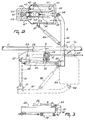
- FIG. 2 shows the robot arm 6 both in the rest position (interrupted lines) and in the operational position (uninterrupted lines).
- the robot arm 6 is connected capably of pivoting about a substantially vertical pivot pin 24 to the frame portion 25 which is attached to the slide block 23.
- This pivotal movement is effected by means of a cylinder 26 which has one end connected to a support 27 of the frame portion 25 and the other end to the first portion 28 of the robot arm 6. It will be obvious that, by operating the cylinder 26, the robot arm 6 can be pivoted from the rest position to the operational position and vice versa. It may be of importance for the robot arm, or a part thereof, to be fixed under spring load, i.e.
- this can be achieved by having the further portion of the robot arm 6 arranged capably of pivoting relative to the first portion thereof about a pin 30 against the action of an excess load spring 29. In the unloaded condition, the further portion of the robot arm 6 is pulled against the first portion 28 of the robot arm 6 by the intermediary of a rubber buffer 31 (see Figure 3).
- the further portion of the robot arm 6 consists of a second portion 32, a third portion 33 and a fourth portion 34.
- the third portion 33 of the robot arm 6 is connected capably of pivoting about a pivot pin 35 to the said second portion 32.
- the pivotal movement about the pivot pin 35 is effected by means of a cylinder 36, the one end of which is connected to the second portion 32 of the robot arm 6 and the other end to a support 37 on the third portion 33 of the robot arm 6.
- the robot arm can be moved to under the animal present in the milking parlour, the pivot pin 35 being approximately in a central position under the animal, i.e. between the animal's front and rear legs.
- the third portion 33 of the robot arm 6 can be pivoted about the pivot pin 35 at a desired angle.
- the fourth portion 34 of the robot arm 6 (i.e. the end thereof) is movable axially relative to the third portion 33, as is indicated by arrows 38.
- the support 37 is movable in a slot-shaped aperture provided on the side of the fourth portion 34 of the robot arm 6.
- the third portion 33 of the robot arm 6 is located partly within the end 34 of the robot arm 6.
- the end 34 of the robot arm 6 being slidable relative to the third portion 33, it is provided with rails 39.
- a cylinder 40 Between the mutually slidable portions 33 and 34 there is arranged a cylinder 40, the one end of which is connected via a support 41 to the third portion 33 of the robot arm 6 and the other end via a support 42 to the end 34 thereof.
- the end 34 of the robot arm 6 can be adjusted in the longitudinal direction under the animal by means of both the cylinder 40 and the cylinder 18. Although in this connection it would be sufficient to use the cylinder 40, it will be possible, by the addition of the cylinder 18, to limit the stroke of the former considerably, which, in view of the restricted space under the animal, is highly advantageous.
- the end 34 of the robot arm 6 is provided with a slide 43 which by means of rails 44 is movable along the robot arm end 34 in the longitudinal direction.
- Teat cups 45, 46, 47 and 48 are provided at the end 34 of the robot arm 6, in which situation, since the robot arm 6 approaches the animal's udder from the front side, the teat cups 45 and 46 are intended for connection to the animal's rear teats and the teat cups 47 and 48 to the front teats.
- the teat cups 45 to 48 are arranged such that the slide 43 can move at least between the teats cups 47 and 48.
- the slide 43 is capable of reciprocating by means of a cylinder 49, one end of which is connected to the slide 43 and the other end to the end 34 of the robot arm 6.
- coupling means 50 On the slide there are provided, taken from the left to the right in Figure 4: coupling means 50, sensor means 51, a pivotal mechanism 52 and a stepper motor 53, the last two units together constituting the pivotal means for the sensor means 51.
- these pivotal means are constituted by a bi-directionally controlable stepper motor.
- the sensor means 51 are secured on the slide 43 by means of supporting plates 54 and 55 (see Figure 5).
- the pivotal means 52, 53 are arranged on the supporting plate 55.
- the slide 43 is provided, under the supporting plate 55, with the sensor electronics 56 required for the sensor means 51.
- the sensor means 51 are mounted such that they are pivotal through a pivotal angle which extends symmetrically relative to the longitudinal direction of the robot arm end 34, which angle in the embodiment is approximately 120°.
- the sensor means 51 are reciprocated by the pivotal means 52, 53 through the pivotal angle in approximately 0.5 second.
- the stepper motor 53 drives the pivotal mechanism 52, while the pivotal mechanism 52 causes the sensor means 51 to reciprocate with the aid of a belt 57.
- a cylinder 58 under the slide 43 there is arranged a cylinder 58 with the aid of which, with the intermediary of a pivotal mechanism 59, the coupling means 50 can be reciprocated through a pivotal angle which also extends symmetrically relative to the longitudinal direction of the robot arm end 34, which angle in the embodiment is approximately 90°.
- the sensor means 51 can determine the position of the front teats, when the slide 43 has been adjusted to a first position; the position of the slide 43 is then also that wherein, during the coupling procedure, the coupling means 50 can engage the teat cups 47 and 48 in order to connect same to the front teats.
- the slide 43 is moved forwards, it can arrive in a second position in which by means of the sensor means 51 the position of the rear teats can be determined and in which the coupling means 50 subsequently can engage the teat cups 45 and 46 in order to connect same to the rear teats. This situation is illustrated in Figures 3 to 5.
- the coupling means 50 can only engage the teat cups 47, 48, respectively 45, 46, individually.
- the cylinder 58 and the pivotal mechanism 59 can first adjust the coupling means to a position wherein they can, for example, engage the respective teat cups 45 and 47 and thereafter to a position wherein they can engage the respective teat cups 46 and 48.
- the sensor means 51 continue to be permanently operative in order to detect the teat positions located within the pivotal angle, even during the subsequent upward movement of the teat cups 45 to 48.
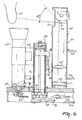
- FIG. 6 shows the sensor means 51 in further detail; they comprise a housing 60 constituted by a cylindrical sleeve and provided with a laser-transparant window 61 near its upper end. Behind the window 61 there is arranged a transmitter element 62 constituted by a laser, which transmitter element 62 is controlled from the sensor electronics 56 and a microprocessor (not indicated in the figures).
- a laser for the sensor means 51 has the advantage that hereby a much narrower scanning beam as well as a much higher data rate can be obtained. Therefore, the transmitter element 62 is capable of transmitting continuously a narrow scanning beam to determine the position of a teat 63. This teat 63 disperses and/or reflects the radiation transmitted by the transmitter element 62.
- a fraction of the radiation returns into the housing 60 and is deflected downwardly by a reflecting element 64, constituted by a flat mirror and located behind the window 61, and is guided to a receiver element 66 including a diode detector via a converging lens 65 accommodated in the housing 60.
- the region on the receiver element 66 where the captured beam is focused to a greater or lesser extent, is decisive for the sensor means-teat distance.
- the signal applied by the receiver element 66 to the sensor electronics 56 is indicative of this focusing region.
- the beam transmitted by the transmitter element 62 extends substantially horizontally and the mirror is arranged at an angle of approximately 45°.
- the angular position of the teat 63 relative to the robot arm end 34 can further be determined from the time interval in which the reflections are received from the teat 63 during the reciprocating movement of the sensor means 51. From the detected position of a teat 63 with respect to the robot arm end 34 signals are generated by control means (to be described in further detail hereinafter) to adjust the robot arm end 34 to such a position that a relevant teat cup can be connected to the teat 63 by moving it upwardly.
- a relevant teat cup can be connected.
- the teat cups 45 to 48 bear on the robot arm end 34 in tapering recesses 67.
- the teat cups 45 to 48 are kept in position therein by flexible connecting members 68 which are coupled to cylinders (not shown) in the fourth part 34 of the robot arm 6.
- the teat cups 45 to 48 can then be moved freely upwardly and are pulled down again by the said cylinders in their positions in the tapering recesses 67 when the supply of milk stops.
- the upward movement of the individual teat cups is effected by the coupling means 50 which are provided with an electromagnet 69 which, after having been energized, can engage the teat cup to which the electromagnet 69 is directed at that instant.
- the coupling means 50 include a vertical inner jacket 70 which is connected rigidly to the slide in the upward direction; this inner jacket 70 can be rotated by the pivotal mechanism 59 through the said pivotal angle of, in this embodiment, 90°.
- the inner jacket 70 is surrounded by an outer jacket 71 which can move only in upward and downward direction.
- the electromagnet 69 is connected rigidly to this outer jacket 71.
- the outer jacket 71 is connected rigidly to a piston 72 which extends through the coupling means 50.
- Compressed air can be applied in the space under the piston 72 via a compressed air supply pipe 73, whereby the outer jacket 71 and the electromagnet 69 connected thereto and the teat cup engaged thereby are moved upwardly.
- the pressure exerted by the compressed air is such that, as soon as the teat cup contacts the cow's udder and, therefore, a certain counter-pressure is exerted, the upward movement of the teat cup is stopped.
- the electromagnet 69 is de-energized and, consequently, the teat cup is no longer retained thereby.
- compressed air can be passed into the space above the piston 72 via the compressed air supply pipe 74, as a result of which the outer jacket 71 with the electromagnet 69 connected thereto can be moved downwardly; in this connection, the pressure on the supply pipe 73 must, of course, be less than that on the supply pipe 74.
- the position of the cylinders 18, 22, 36 and 40 is of importance.
- Each of these cylinders is provided in a known per se manner with control electronics (not indicated in the figures).
- the cylinders 18 and 22 are utilized. The adjustment in the longitudinal direction is determined roughly by means of the cylinder 18, while by means of the cylinder 22 is determined roughly the height.
- the cylinder 22 is also utilized for a searching movement performed by the sensor means 51.
- the cylinders 36 and 40 are utilized. “Roughly determined” does not imply that an inaccurate measurement is made, but that the measurement registers an instantaneous indication; for the teat will be moving continuously.
- the actual position of the cylinders 18, 22, 36 and 40 can be supplied to the microprocessor and be registered in memory means thereof.
- the desired position of the cylinders 36 and 40 can be supplied to these cylinders 36 and 40.
- the cylinders 18 and 22 With respect to the cylinders 18 and 22, it will suffice to supply from the microprocessor only two signals to the relevant control electronics; by means of these signals can be indicated whether the cylinders 18 and/or 22 have to be activated or stopped, and in what direction the cylinders have to control the end 34 of the robot arm 6. Besides in roughly adjusting the end 34 of the robot arm 6, the cylinder 22 is also utilized in moving the laser in the vertical direction, and hence the end 34 of the robot arm 6 during the "searching procedure".
- the cylinders 18, 20, 22, 26, 36, 40, 49 and 58 can be operable either hydraulically, pneumatically or electromagnetically. Insofar as hydraulically or electromagnetically operable cylinders are utilized, it is strongly desirable to include an additional overload protection against kicks from the animal.
- the cylinders 18 and 22 which are relevant to the determination of the position of the teats are electromagnetically operable, while the cylinders 36 and 40 are pneumatically operable, in which connection the control electronics are designed such that these cylinders can reach very quickly a specific position determined by the microprocessor.
- Servopneumatic positioning elements constituted by a pneumatic cylinder with associated control electronics, are known per se, but in the present implement, in co-operation with a laser in the sensor means, they render it possible for the teat cups to be connected to the teats in an extremely fast and efficient manner.
- the animal recognition is of importance to the present invention to the extent that thereby is known for each animal the position of the teats of the animal's udder relative to a fixed point on the animal, while, furthermore, this position in the animal recognition data source can be corrected, if necessary, on the basis of the continuously occurring "searching and tracking procedure".
- searching procedure it is of importance that is registered the position of the teats relative to a reference position, here a point on the animal's rear centre as determined by the sensor device 4.
- the point in the aperture of the housing wherein the laser is accommodated and from where the horizontal laser scan movement takes place is located at a predetermined slight distance below and in the middle in front of the front teats, e.g. 50 mms below the front teats and 120 mms in the middle in front thereof.
- the then actual position of the cylinders is registered and the laser is started.
- the cylinder 22 is activated, after which the robot arm end with the laser is moved upwardly, during which movement the laser performs its scanning movement, each scanning movement taking e.g. 0.25 second.
- reflected laser signals particularly from the two front teats are registered permanently, as well as the associated position of the cylinder 22.
- the laser is positioned in the starting position below and in the middle in front of the rear teats and the above-described procedure is repeated, after which also the position of the rear teats is registered.
- the searching procedure no agreement within certain limits is established between the calculated position of the objects observed and the relevant data from the animal recognition data source, then the searching is continued.
- the laser is moved higher upwardly and, after having reached its highest position of e.g. 100 mms above its starting position, returns to this starting position in order to perform another searching movement in the vertical direction.
- an alarm is operated.
- the searching procedure follows the tracking procedure, in which the teats are tracked individually in order to be able to connect a teat cup thereto.
- the teats are numbered, so that a fixed order can be observed.
- one of the rear teats is tracked; the laser is already in the right starting position therefor, i.e. the position wherein the cylinder 22 has stopped during the search for the rear teats.
- the data flow of the laser, as well as the position of the relevant cylinders is registered permanently. From the laser data is calculated continuously the position of the teat relative to the laser and therefrom the difference between the position of the teat relative to the laser and the position of the relevant teat cup relative to the laser. When these differences are not slight enough, i.e.
- the results of the last measurement are compared with the teat position corrected on the basis of the previous measurement; in the present embodiment.
- the cylinders have to be activated and the relevant teat cup, i.e. the end of the robot arm, has to be dispatched to the lastly determined teat position. This procedure is repeated until the difference between the position of the teat relative to the laser and that of the teat cup relative to the laser is slight enough, so that the teat cup is located almost straight below the relevant teat.
- the teat cup is then moved upwardly and connected, while by means of a vacuum under the teat it is checked whether the teat cup is connected correctly. During this upward movement of the teat cup, the tracking procedure remains active, so that even then the teat cup can be controlled yet.
Abstract
Description
- The present invention relates to a laser sensor device for measuring the distance between the sensor and an object, which device comprises a laser accommodated in a housing, the laser transmitting to the object a beam through a window in the housing, whereby a fraction of the beam radiation dispersed by and/or reflected by the object, passes a lens, which is accommodated in the housing, and is detected by means of a receiver element.
- A laser sensor device as described above is generally known, e.g. as a laser distance sensor. The invention has for its object to provide an improved laser sensor device. According to the inventions this is achieved in that the housing is provided with a reflecting element for guiding the radiation dispersed by and/or reflected by the object to the receiver element. By means of the reflecting element it is possible to place the receiver element on different locations in the housing. According to the invention the laser, the reflecting element, the lens and the receiver element are arranged in said order and at some distance from each other on an imaginary line, in the housing. In a preferred embodiment according to the invention, the beam transmitted by the laser and the imaginary line meet at an angle of 90°. In accordance with the invention, in this case the reflecting element is arranged at an angle of approximately 45° with the beam transmitted by the laser. In accordance with a further aspect of the invention, the housing is constituted by a cilindrical sleeve, whereby the laser-transparant window is provided at one end of the sleeve.
- The above described laser sensor device is, in accordance with the invention, especially suitable to be used in a milking robot. According to the invention, in this case the laser sensor device is arranged on a robot arm, adapted to carry near its end one or more teat cups and coupling means for applying each teat cup to a relevant teat of an animal's udder, after the position of said teat is determined by means of the laser sensor device. Due to the cilindrical housing, the tracking with the scanning beam of the laser takes place just above the teat cups.
- For a better understanding of the present invention and to show how the same may be carried into effect, reference will now be made, by way of example, to the accompanying drawings, in which:
- Figure 1 is a side view of a robot arm arranged at the side of a milking parlour;
- Figure 2 is a plan view of the robot arm;
- Figure 3 is a side view of part of the robot arm as shown in Figure 2;
- Figure 4 is a plan view of the end of the robot arm;
- Figure 5 is a side view of the robot arm end as shown in Figure 4, and
- Figure 6 is a partial cross-sectional view taken on the line VI - VI in Figure 4.
- In the drawings, corresponding components have been denoted by the same reference numerals. In addition, the invention is not limited to the embodiment as shown and described here, which embodiment only serves to illustrate the inventive idea.
- In Figures 1 and 2, the robot arm according to the invention is shown; this robot arm is arranged at the side of a milking parlour. Once an animal to be milked has arrived in the milking parlour and has been positioned appropriately therein, the robot arm is moved, on the basis of animal recognition data, from the front side to under the animal's udder.
- In the side view of the implement of Figure 1 there is shown an
animal 1 which is present in the milking parlour, the milking parlour being enclosed by a railing 2 which limits the freedom of movement of theanimal 1 in a lateral direction. The milking parlour is entered by the animal from the rear, while apivotal stop 3 is arranged near the front side, whichstop 3 constitutes a boundary for theanimal 1 in the forward direction. By providing the front side of the milking parlour with e.g. a feed unit, the animal will advance sufficiently far, i.e. until against thestop 3. - The milking parlour floor has a recess, which is arranged such that the animal will not put her hind feet thereon, e.g. because its bottom extends obliquely inwardly and downwardly, so that the hind legs of the animal are wide apart and on either side of the recess. The recess may have a drain for discharging the animal's excrements, if any.
- Once the animal has entered the milking parlour, a
sensor device 4 is pivoted against her rear side. At the side of the milking parlour there is arranged a substantiallyvertical frame beam 5, whichframe beam 5 at its upper end is provided with a longitudinal guide means and to which near its lower end arobot arm 6 is fitted. Thevertical frame beam 5 is capable of moving with respect to the milking parlour in the longitudinal direction as denoted by thearrows 7. For that purpose, the railing is provided with a guide rod 8, along which can move twointerconnected slide blocks 9, 10, the saidslide blocks 9, 10 being interconnected by means of ahorizontal frame beam 11 secured to thevertical frame beam 5. Near the floor, theframe beam 5 is guided by aguide rail 12, along which the lower portion offrame beam 5 slides. - The
sensor device 4 is connected pivotably to a slide element 13 which by means of twoslide blocks 14, 15 is arranged also slidably along the guide rod 8. Between twolugs slide block 10, respectively, acylinder 18, while furthermore between the slide element 13 and a support 19 on the railing 2 there is arranged a cylinder 20. By operating the cylinder 20, thesensor device 4 can be moved towards the animal until, in the downward position, it bears against the animal's rear. In the present embodiment, the sensor device, and hence the animal's rear, determines the reference position, relative to which the position of the teats and that of the milking robot are determined. By moving thesensor device 4 towards the animal, it is also possible to move theframe beam 5, as a result of which the mutual positioning between thesensor device 4 and theframe beam 5 can be provided adjustably by means of thecylinder 18. - A
robot arm 6 is connected slidably in height (arrows 21) to theframe beam 5. The sliding movement in height is effected by means of acylinder 22, the one end of which is connected to theframe beams cylinder 22 is connected to aslide block 23 which is capable of moving in height along theframe beam 5 in dependence on the operation of thecylinder 22. - Figure 2 shows the
robot arm 6 both in the rest position (interrupted lines) and in the operational position (uninterrupted lines). Therobot arm 6 is connected capably of pivoting about a substantiallyvertical pivot pin 24 to theframe portion 25 which is attached to theslide block 23. This pivotal movement is effected by means of acylinder 26 which has one end connected to asupport 27 of theframe portion 25 and the other end to thefirst portion 28 of therobot arm 6. It will be obvious that, by operating thecylinder 26, therobot arm 6 can be pivoted from the rest position to the operational position and vice versa. It may be of importance for the robot arm, or a part thereof, to be fixed under spring load, i.e. in such a manner that it, or the said portion thereof, can deflect when e.g. the animal kicks against it. In this embodiment, this can be achieved by having the further portion of therobot arm 6 arranged capably of pivoting relative to the first portion thereof about apin 30 against the action of anexcess load spring 29. In the unloaded condition, the further portion of therobot arm 6 is pulled against thefirst portion 28 of therobot arm 6 by the intermediary of a rubber buffer 31 (see Figure 3). - The further portion of the
robot arm 6 consists of asecond portion 32, athird portion 33 and afourth portion 34. Thethird portion 33 of therobot arm 6 is connected capably of pivoting about apivot pin 35 to the saidsecond portion 32. The pivotal movement about thepivot pin 35 is effected by means of acylinder 36, the one end of which is connected to thesecond portion 32 of therobot arm 6 and the other end to asupport 37 on thethird portion 33 of therobot arm 6. As is apparent from Figure 2, by means of thecylinder 26, the robot arm can be moved to under the animal present in the milking parlour, thepivot pin 35 being approximately in a central position under the animal, i.e. between the animal's front and rear legs. Thereafter, by operating thecylinder 36, thethird portion 33 of therobot arm 6 can be pivoted about thepivot pin 35 at a desired angle. - The
fourth portion 34 of the robot arm 6 (i.e. the end thereof) is movable axially relative to thethird portion 33, as is indicated byarrows 38. In this connection, thesupport 37 is movable in a slot-shaped aperture provided on the side of thefourth portion 34 of therobot arm 6. - In the inserted condition, the
third portion 33 of therobot arm 6 is located partly within theend 34 of therobot arm 6. Theend 34 of therobot arm 6 being slidable relative to thethird portion 33, it is provided withrails 39. Between the mutuallyslidable portions cylinder 40, the one end of which is connected via asupport 41 to thethird portion 33 of therobot arm 6 and the other end via asupport 42 to theend 34 thereof. - The
end 34 of therobot arm 6 can be adjusted in the longitudinal direction under the animal by means of both thecylinder 40 and thecylinder 18. Although in this connection it would be sufficient to use thecylinder 40, it will be possible, by the addition of thecylinder 18, to limit the stroke of the former considerably, which, in view of the restricted space under the animal, is highly advantageous. - The
end 34 of therobot arm 6 is provided with aslide 43 which by means ofrails 44 is movable along therobot arm end 34 in the longitudinal direction.Teat cups end 34 of therobot arm 6, in which situation, since therobot arm 6 approaches the animal's udder from the front side, theteat cups teat cups teat cups 45 to 48 are arranged such that theslide 43 can move at least between theteats cups slide 43 is capable of reciprocating by means of acylinder 49, one end of which is connected to theslide 43 and the other end to theend 34 of therobot arm 6. On the slide there are provided, taken from the left to the right in Figure 4: coupling means 50, sensor means 51, apivotal mechanism 52 and astepper motor 53, the last two units together constituting the pivotal means for the sensor means 51. In the embodiment shown in Figure 7, these pivotal means are constituted by a bi-directionally controlable stepper motor. The sensor means 51 are secured on theslide 43 by means of supportingplates 54 and 55 (see Figure 5). The pivotal means 52, 53 are arranged on the supportingplate 55. In addition, theslide 43 is provided, under the supportingplate 55, with thesensor electronics 56 required for the sensor means 51. - The sensor means 51 are mounted such that they are pivotal through a pivotal angle which extends symmetrically relative to the longitudinal direction of the
robot arm end 34, which angle in the embodiment is approximately 120°. The sensor means 51 are reciprocated by the pivotal means 52, 53 through the pivotal angle in approximately 0.5 second. Thestepper motor 53 drives thepivotal mechanism 52, while thepivotal mechanism 52 causes the sensor means 51 to reciprocate with the aid of abelt 57. In addition, under theslide 43 there is arranged acylinder 58 with the aid of which, with the intermediary of apivotal mechanism 59, the coupling means 50 can be reciprocated through a pivotal angle which also extends symmetrically relative to the longitudinal direction of therobot arm end 34, which angle in the embodiment is approximately 90°. After therobot arm end 34 has been positioned approximately below the animal's udder, the sensor means 51 can determine the position of the front teats, when theslide 43 has been adjusted to a first position; the position of theslide 43 is then also that wherein, during the coupling procedure, the coupling means 50 can engage the teat cups 47 and 48 in order to connect same to the front teats. When thereafter theslide 43 is moved forwards, it can arrive in a second position in which by means of the sensor means 51 the position of the rear teats can be determined and in which the coupling means 50 subsequently can engage the teat cups 45 and 46 in order to connect same to the rear teats. This situation is illustrated in Figures 3 to 5. In both the first (front) and the second (rear) position of theslide 43, the coupling means 50 can only engage the teat cups 47, 48, respectively 45, 46, individually. In both positions, thecylinder 58 and thepivotal mechanism 59 can first adjust the coupling means to a position wherein they can, for example, engage the respective teat cups 45 and 47 and thereafter to a position wherein they can engage the respective teat cups 46 and 48. The sensor means 51 continue to be permanently operative in order to detect the teat positions located within the pivotal angle, even during the subsequent upward movement of the teat cups 45 to 48. - Figure 6 shows the sensor means 51 in further detail; they comprise a
housing 60 constituted by a cylindrical sleeve and provided with a laser-transparantwindow 61 near its upper end. Behind thewindow 61 there is arranged atransmitter element 62 constituted by a laser, whichtransmitter element 62 is controlled from thesensor electronics 56 and a microprocessor (not indicated in the figures). The use of a laser for the sensor means 51 has the advantage that hereby a much narrower scanning beam as well as a much higher data rate can be obtained. Therefore, thetransmitter element 62 is capable of transmitting continuously a narrow scanning beam to determine the position of ateat 63. Thisteat 63 disperses and/or reflects the radiation transmitted by thetransmitter element 62. Via thewindow 61, a fraction of the radiation returns into thehousing 60 and is deflected downwardly by a reflectingelement 64, constituted by a flat mirror and located behind thewindow 61, and is guided to areceiver element 66 including a diode detector via a converginglens 65 accommodated in thehousing 60. The region on thereceiver element 66 where the captured beam is focused to a greater or lesser extent, is decisive for the sensor means-teat distance. The signal applied by thereceiver element 66 to thesensor electronics 56 is indicative of this focusing region. In the present embodiment, the beam transmitted by thetransmitter element 62 extends substantially horizontally and the mirror is arranged at an angle of approximately 45°. The angular position of theteat 63 relative to therobot arm end 34 can further be determined from the time interval in which the reflections are received from theteat 63 during the reciprocating movement of the sensor means 51. From the detected position of ateat 63 with respect to therobot arm end 34 signals are generated by control means (to be described in further detail hereinafter) to adjust therobot arm end 34 to such a position that a relevant teat cup can be connected to theteat 63 by moving it upwardly. - As soon as the
robot arm end 34 has arrived in the desired position, a relevant teat cup can be connected. In the present embodiment, the teat cups 45 to 48 bear on therobot arm end 34 in tapering recesses 67. The teat cups 45 to 48 are kept in position therein by flexible connectingmembers 68 which are coupled to cylinders (not shown) in thefourth part 34 of therobot arm 6. The teat cups 45 to 48 can then be moved freely upwardly and are pulled down again by the said cylinders in their positions in the tapering recesses 67 when the supply of milk stops. The upward movement of the individual teat cups is effected by the coupling means 50 which are provided with an electromagnet 69 which, after having been energized, can engage the teat cup to which the electromagnet 69 is directed at that instant. By rotation of the coupling means 50 and by a change in the position of theslide 43, the electromagnet 69 can be directed to the other teat cups which can then be engaged after energizing of the electromagnet 69. The coupling means 50 include a verticalinner jacket 70 which is connected rigidly to the slide in the upward direction; thisinner jacket 70 can be rotated by thepivotal mechanism 59 through the said pivotal angle of, in this embodiment, 90°. Theinner jacket 70 is surrounded by an outer jacket 71 which can move only in upward and downward direction. The electromagnet 69 is connected rigidly to this outer jacket 71. The outer jacket 71 is connected rigidly to a piston 72 which extends through the coupling means 50. Compressed air can be applied in the space under the piston 72 via a compressedair supply pipe 73, whereby the outer jacket 71 and the electromagnet 69 connected thereto and the teat cup engaged thereby are moved upwardly. The pressure exerted by the compressed air is such that, as soon as the teat cup contacts the cow's udder and, therefore, a certain counter-pressure is exerted, the upward movement of the teat cup is stopped. When a teat cup has been connected to therelevant teat 63, the electromagnet 69 is de-energized and, consequently, the teat cup is no longer retained thereby. Subsequently, compressed air can be passed into the space above the piston 72 via the compressedair supply pipe 74, as a result of which the outer jacket 71 with the electromagnet 69 connected thereto can be moved downwardly; in this connection, the pressure on thesupply pipe 73 must, of course, be less than that on thesupply pipe 74. - In determining the position of the teats of the animal's udder, the position of the
cylinders end 34 of therobot arm 6 in the centre below the animal, thecylinders cylinder 18, while by means of thecylinder 22 is determined roughly the height. Thecylinder 22 is also utilized for a searching movement performed by the sensor means 51. During the "searching procedure" for roughly determining the position of the teats of the animal's udder relative to a reference position and the "tracking procedure" for accurately determining the position of the teats of the animal's udder relative to a reference position, thecylinders cylinders cylinders cylinders cylinders cylinders 18 and/or 22 have to be activated or stopped, and in what direction the cylinders have to control theend 34 of therobot arm 6. Besides in roughly adjusting theend 34 of therobot arm 6, thecylinder 22 is also utilized in moving the laser in the vertical direction, and hence theend 34 of therobot arm 6 during the "searching procedure". Thecylinders cylinders cylinders - When the animal arrives in the milking parlour, she will be identified by means of a conventional animal recognition data source. The animal recognition is of importance to the present invention to the extent that thereby is known for each animal the position of the teats of the animal's udder relative to a fixed point on the animal, while, furthermore, this position in the animal recognition data source can be corrected, if necessary, on the basis of the continuously occurring "searching and tracking procedure". For the searching procedure it is of importance that is registered the position of the teats relative to a reference position, here a point on the animal's rear centre as determined by the
sensor device 4. First of all, the end of the robot arm is brought into such a starting position that the laser, i.e. the point in the aperture of the housing wherein the laser is accommodated and from where the horizontal laser scan movement takes place, is located at a predetermined slight distance below and in the middle in front of the front teats, e.g. 50 mms below the front teats and 120 mms in the middle in front thereof. The then actual position of the cylinders is registered and the laser is started. Then, thecylinder 22 is activated, after which the robot arm end with the laser is moved upwardly, during which movement the laser performs its scanning movement, each scanning movement taking e.g. 0.25 second. During this upward movement, reflected laser signals, particularly from the two front teats are registered permanently, as well as the associated position of thecylinder 22. From this data is calculated the position, relative to that of the laser, of the objects observed, which are not yet considered as teats. From the position of the cylinders is calculated the position of the laser relative to the reference position. On the basis of the results of the two last calculations is calculated the position of the objects observed relative to the reference position. Subsequently, this last position is compared with the data regarding this position as derived from the animal recognition data source. Should there be established an agreement within certain limits, then the objects observed are identified as the animal's front teats, this position of the front teats is registered and the upward movement of thecylinder 22 is stopped. Subsequently, the laser is positioned in the starting position below and in the middle in front of the rear teats and the above-described procedure is repeated, after which also the position of the rear teats is registered. This completes the "searching procedure". In case, during the searching procedure, no agreement within certain limits is established between the calculated position of the objects observed and the relevant data from the animal recognition data source, then the searching is continued. Then, the laser is moved higher upwardly and, after having reached its highest position of e.g. 100 mms above its starting position, returns to this starting position in order to perform another searching movement in the vertical direction. When after a number of searching movements still no teats have been identified, an alarm is operated. - After the searching procedure follows the tracking procedure, in which the teats are tracked individually in order to be able to connect a teat cup thereto. In this tracking procedure, the teats are numbered, so that a fixed order can be observed. First, one of the rear teats is tracked; the laser is already in the right starting position therefor, i.e. the position wherein the
cylinder 22 has stopped during the search for the rear teats. Here again, the data flow of the laser, as well as the position of the relevant cylinders, is registered permanently. From the laser data is calculated continuously the position of the teat relative to the laser and therefrom the difference between the position of the teat relative to the laser and the position of the relevant teat cup relative to the laser. When these differences are not slight enough, i.e. the teat cup is located not quite below the relevant teat, then the results of the last measurement are compared with the teat position corrected on the basis of the previous measurement; in the present embodiment. When the latter differences are less than a certain value of e.g. 35 mms, then the cylinders have to be activated and the relevant teat cup, i.e. the end of the robot arm, has to be dispatched to the lastly determined teat position. This procedure is repeated until the difference between the position of the teat relative to the laser and that of the teat cup relative to the laser is slight enough, so that the teat cup is located almost straight below the relevant teat. The teat cup is then moved upwardly and connected, while by means of a vacuum under the teat it is checked whether the teat cup is connected correctly. During this upward movement of the teat cup, the tracking procedure remains active, so that even then the teat cup can be controlled yet. - From the finally registered position of the teat cup at the moment of connection and the mutual position of the teats, as can be obtained from the teat position determination in the searching procedure, there can be obtained a corrected initial position of the laser for the tracking of the second rear teat. After the laser has been brought in this corrected initial position, the above-described tracking procedure is repeated and the second teat cup can be connected. Likewise, the third and fourth teat cups are connected, after which the tracking procedure is completed.
Claims (13)
- Laser sensor device for measuring the distance between the sensor (51) and an object, which device comprises a laser (62), accommodated in a housing (60), the laser (62) transmitting to the object a beam through a window (61) in the housing (60), whereby a fraction of the beam radiation dispersed by and/or reflected by the object, passes a lens (65), which is accommodated in the housing (60), and is detected by means of a receiver element (66), characterized in that in the housing (60) there is provided a reflecting element (64) for guiding the radiation dispersed by and/or reflected by the object to the receiver element (66).
- Laser sensor device as claimed in claim 1, characterized in that the laser (62), the reflecting element (64), the lens (65) and the receiver element (66) are arranged in said order and at some distance from each other on an imaginary line.
- Laser sensor device as claimed in claim 2, characterized in that the beam, transmitted by the laser (62) and the imaginary line meet at an angle of 90°.
- Laser sensor device as claimed in claim 3, characterized in that the reflecting element (64) is arranged at an angle of approximately 45° with the beam transmitted by the laser (62).
- Laser sensor device as claimed in any one of the preceding claims, characterized in that the housing (60) is constituted by a cilindrical sleeve, whereby the laser-transparant window (61) is provided at one end of the sleeve.
- Laser sensor device as claimed in claim 5, characterized in that the imaginary line is in the longitudinal direction of the cilindrical housing (60).
- Laser sensor device as claimed in any one of the preceding claims, characterized in that the reflecting element (64) is arranged near the laser (62).
- Laser sensor device as claimed in any one of the preceding claims, characterized in that the receiver element (66) is constituted by a diode detector.
- Laser sensor device as claimed in claim 8, characterized in that the diode detector (66) is provided at the other end of the cilindrical sleeve than where the window (61) is arranged.
- Laser sensor device as claimed in any one of the preceding claims, characterized in that the reflecting element (64) is constituted by a flat mirror which is located behind the window (61).
- Laser sensor device, as claimed in any one of the preceding claims, characterized in that the lens (65) is constituted by a converging lens, which is arranged between the reflecting element (64) and the receiver element (66).
- Laser sensor device, as claimed in any one of the preceding claims, characterized in that the laser sensor device (51) is arranged on a robot arm (6), adapted to carry near its end one or more teat cups (45 to 48), and coupling means (50) for applying each teat cup (45 to 48) to a relevant teat (63) of an animal's udder, after the position of said teat is determined by means of the laser sensor device.
- Implement for automatic milking animals, provided with a laser sensor device according to one or more of the above claims.
Applications Claiming Priority (3)
| Application Number | Priority Date | Filing Date | Title |
|---|---|---|---|
| NL8802332 | 1988-09-21 | ||
| NL8802332A NL8802332A (en) | 1988-09-21 | 1988-09-21 | APPARATUS FOR MILKING AN ANIMAL. |
| EP91202679A EP0472247B2 (en) | 1988-09-21 | 1989-09-20 | An implement for automatically milking an animal |
Related Parent Applications (2)
| Application Number | Title | Priority Date | Filing Date |
|---|---|---|---|
| EP91202679A Division EP0472247B2 (en) | 1988-09-21 | 1989-09-20 | An implement for automatically milking an animal |
| EP91202679.6 Division | 1991-10-16 |
Publications (2)
| Publication Number | Publication Date |
|---|---|
| EP0574089A2 true EP0574089A2 (en) | 1993-12-15 |
| EP0574089A3 EP0574089A3 (en) | 1994-01-05 |
Family
ID=19852940
Family Applications (12)
| Application Number | Title | Priority Date | Filing Date |
|---|---|---|---|
| EP91202679A Expired - Lifetime EP0472247B2 (en) | 1988-09-21 | 1989-09-20 | An implement for automatically milking an animal |
| EP97200483A Expired - Lifetime EP0777962B1 (en) | 1988-09-21 | 1989-09-20 | An implement for milking animals |
| EP91202449A Expired - Lifetime EP0467489B2 (en) | 1988-09-21 | 1989-09-20 | An implement for milking an animal |
| EP19930201643 Withdrawn EP0574089A3 (en) | 1988-09-21 | 1989-09-20 | A laser sensor device |
| EP93201044A Expired - Lifetime EP0553940B1 (en) | 1988-09-21 | 1989-09-20 | An implement for automatically milking animals |
| EP91203326A Revoked EP0479397B1 (en) | 1988-09-21 | 1989-09-20 | An implement for milking an animal |
| EP94203288A Revoked EP0643908B1 (en) | 1988-09-21 | 1989-09-20 | An implement for milking animals |
| EP94203287A Revoked EP0643907B1 (en) | 1988-09-21 | 1989-09-20 | A method of milking an animal |
| EP89202372A Expired - Lifetime EP0360354B2 (en) | 1988-09-21 | 1989-09-20 | An implement for milking an animal as well as a method of connecting teat cups to the teats of same |
| EP91202890A Revoked EP0480542B1 (en) | 1988-09-21 | 1989-09-20 | A method of automatically milking an animal |
| EP94203259A Expired - Lifetime EP0647393B1 (en) | 1988-09-21 | 1989-09-20 | An implement for milking an animal |
| EP94203280A Revoked EP0640282B1 (en) | 1988-09-21 | 1989-09-20 | An implement for milking an animal |
Family Applications Before (3)
| Application Number | Title | Priority Date | Filing Date |
|---|---|---|---|
| EP91202679A Expired - Lifetime EP0472247B2 (en) | 1988-09-21 | 1989-09-20 | An implement for automatically milking an animal |
| EP97200483A Expired - Lifetime EP0777962B1 (en) | 1988-09-21 | 1989-09-20 | An implement for milking animals |
| EP91202449A Expired - Lifetime EP0467489B2 (en) | 1988-09-21 | 1989-09-20 | An implement for milking an animal |
Family Applications After (8)
| Application Number | Title | Priority Date | Filing Date |
|---|---|---|---|
| EP93201044A Expired - Lifetime EP0553940B1 (en) | 1988-09-21 | 1989-09-20 | An implement for automatically milking animals |
| EP91203326A Revoked EP0479397B1 (en) | 1988-09-21 | 1989-09-20 | An implement for milking an animal |
| EP94203288A Revoked EP0643908B1 (en) | 1988-09-21 | 1989-09-20 | An implement for milking animals |
| EP94203287A Revoked EP0643907B1 (en) | 1988-09-21 | 1989-09-20 | A method of milking an animal |
| EP89202372A Expired - Lifetime EP0360354B2 (en) | 1988-09-21 | 1989-09-20 | An implement for milking an animal as well as a method of connecting teat cups to the teats of same |
| EP91202890A Revoked EP0480542B1 (en) | 1988-09-21 | 1989-09-20 | A method of automatically milking an animal |
| EP94203259A Expired - Lifetime EP0647393B1 (en) | 1988-09-21 | 1989-09-20 | An implement for milking an animal |
| EP94203280A Revoked EP0640282B1 (en) | 1988-09-21 | 1989-09-20 | An implement for milking an animal |
Country Status (6)
| Country | Link |
|---|---|
| US (1) | US5042428A (en) |
| EP (12) | EP0472247B2 (en) |
| AT (5) | ATE114105T1 (en) |
| DE (11) | DE68905276T2 (en) |
| ES (5) | ES2064892T5 (en) |
| NL (1) | NL8802332A (en) |
Cited By (26)
| Publication number | Priority date | Publication date | Assignee | Title |
|---|---|---|---|---|
| WO1996011568A2 (en) * | 1994-10-12 | 1996-04-25 | Maasland N.V. | A method of and an implement for automatically milking animals, such as cows |
| DE19927502A1 (en) * | 1999-05-22 | 2000-11-23 | Volkswagen Ag | Distance sensing arrangement for motor vehicle has essentially rod-shaped housing that is transparent, at least in scanner's wavelength range, in region of laser scanner light beam outlet |
| EP1679000A2 (en) * | 1994-03-25 | 2006-07-12 | Maasland N.V. | A construction including an implement for milking animals |
| US8393296B2 (en) | 2011-04-28 | 2013-03-12 | Technologies Holdings Corp. | Milking box with robotic attacher including rotatable gripping portion and nozzle |
| US8590488B2 (en) | 2010-08-31 | 2013-11-26 | Technologies Holdings Corp. | Vision system for facilitating the automated application of disinfectant to the teats of dairy livestock |
| US8671885B2 (en) | 2011-04-28 | 2014-03-18 | Technologies Holdings Corp. | Vision system for robotic attacher |
| US8683946B2 (en) | 2011-04-28 | 2014-04-01 | Technologies Holdings Corp. | System and method of attaching cups to a dairy animal |
| US8746176B2 (en) | 2011-04-28 | 2014-06-10 | Technologies Holdings Corp. | System and method of attaching a cup to a dairy animal according to a sequence |
| US8800487B2 (en) | 2010-08-31 | 2014-08-12 | Technologies Holdings Corp. | System and method for controlling the position of a robot carriage based on the position of a milking stall of an adjacent rotary milking platform |
| US8885891B2 (en) | 2011-04-28 | 2014-11-11 | Technologies Holdings Corp. | System and method for analyzing data captured by a three-dimensional camera |
| US8903129B2 (en) | 2011-04-28 | 2014-12-02 | Technologies Holdings Corp. | System and method for filtering data captured by a 2D camera |
| US9043988B2 (en) | 2011-04-28 | 2015-06-02 | Technologies Holdings Corp. | Milking box with storage area for teat cups |
| US9049843B2 (en) | 2011-04-28 | 2015-06-09 | Technologies Holdings Corp. | Milking box with a robotic attacher having a three-dimensional range of motion |
| US9058657B2 (en) | 2011-04-28 | 2015-06-16 | Technologies Holdings Corp. | System and method for filtering data captured by a 3D camera |
| US9107379B2 (en) | 2011-04-28 | 2015-08-18 | Technologies Holdings Corp. | Arrangement of milking box stalls |
| US9149018B2 (en) | 2010-08-31 | 2015-10-06 | Technologies Holdings Corp. | System and method for determining whether to operate a robot in conjunction with a rotary milking platform based on detection of a milking claw |
| US9161512B2 (en) | 2011-04-28 | 2015-10-20 | Technologies Holdings Corp. | Milking box with robotic attacher comprising an arm that pivots, rotates, and grips |
| US9161511B2 (en) | 2010-07-06 | 2015-10-20 | Technologies Holdings Corp. | Automated rotary milking system |
| US9215861B2 (en) | 2011-04-28 | 2015-12-22 | Technologies Holdings Corp. | Milking box with robotic attacher and backplane for tracking movements of a dairy animal |
| US9258975B2 (en) | 2011-04-28 | 2016-02-16 | Technologies Holdings Corp. | Milking box with robotic attacher and vision system |
| US9265227B2 (en) | 2011-04-28 | 2016-02-23 | Technologies Holdings Corp. | System and method for improved attachment of a cup to a dairy animal |
| US9357744B2 (en) | 2011-04-28 | 2016-06-07 | Technologies Holdings Corp. | Cleaning system for a milking box stall |
| US9681634B2 (en) | 2011-04-28 | 2017-06-20 | Technologies Holdings Corp. | System and method to determine a teat position using edge detection in rear images of a livestock from two cameras |
| US10111401B2 (en) | 2010-08-31 | 2018-10-30 | Technologies Holdings Corp. | System and method for determining whether to operate a robot in conjunction with a rotary parlor |
| US10127446B2 (en) | 2011-04-28 | 2018-11-13 | Technologies Holdings Corp. | System and method for filtering data captured by a 2D camera |
| US10357015B2 (en) | 2011-04-28 | 2019-07-23 | Technologies Holdings Corp. | Robotic arm with double grabber and method of operation |
Families Citing this family (138)
| Publication number | Priority date | Publication date | Assignee | Title |
|---|---|---|---|---|
| US5568788A (en) * | 1990-02-27 | 1996-10-29 | C. Van Der Lely N.V. | Implement for and a method of milking animals automatically |
| NL9101636A (en) * | 1991-09-27 | 1993-04-16 | Lely Nv C Van Der | METHOD FOR AUTOMATIC MILKING OF ANIMALS. |
| NL9001076A (en) * | 1990-05-04 | 1991-12-02 | Lely Nv C Van Der | DEVICE FOR DETERMINING THE DISTANCE OF AN APPARATUS TO AN OBJECT. |
| NL9100992A (en) * | 1991-06-10 | 1993-01-04 | Lely Nv C Van Der | DEVICE FOR MILKING ANIMALS. |
| GB9113405D0 (en) * | 1991-06-20 | 1991-08-07 | Silsoe Research Inst | Automatic milking |
| NL9101673A (en) * | 1991-10-04 | 1993-05-03 | Texas Industries Inc | Apparatus for cleaning teats of milking animals. |
| DK0535754T3 (en) * | 1991-10-04 | 1998-03-09 | Lely Nv C Van Der | Tool for milking animals and method of finishing |
| NL9200091A (en) * | 1992-01-17 | 1993-08-16 | Lely Nv C Van Der | MILK MACHINE. |
| NL9200639A (en) * | 1992-04-06 | 1993-11-01 | Lely Nv C Van Der | DEVICE FOR AUTOMATIC MILKING OF ANIMALS. |
| NL9200678A (en) * | 1992-04-13 | 1993-11-01 | Lely Nv C Van Der | Apparatus for the automatic milking of animals, such as cows. |
| US5697324A (en) * | 1993-06-25 | 1997-12-16 | Van Der Lely; Cornelis | Apparatus for automatically milking animals, such as cows |
| NL9201127A (en) * | 1992-06-25 | 1994-01-17 | Lely Nv C Van Der | APPARATUS FOR AUTOMATIC MILKING OF ANIMALS, SUCH AS COWS. |
| AU664282B2 (en) * | 1992-06-25 | 1995-11-09 | Lely Patent N.V. | A construction for automatically milking animals, such as cows |
| NL9201877A (en) * | 1992-10-29 | 1994-05-16 | Lely Nv C Van Der | Device for milking animals. |
| WO1994009616A2 (en) * | 1992-11-02 | 1994-05-11 | C. Van Der Lely N.V. | A construction for automatically milking animals |
| NL9300143A (en) * | 1993-01-26 | 1994-08-16 | Lely Nv C Van Der | Milking machine. |
| NL9300242A (en) * | 1993-02-08 | 1994-09-01 | Lely Nv C Van Der | Device for milking animals. |
| NL9300443A (en) * | 1993-03-11 | 1994-10-03 | Prolion Bv | Method and device for monitoring animal functions. |
| NL9300578A (en) * | 1993-04-01 | 1994-11-01 | Texas Industries Inc | Device for automatic milking of animals. |
| NL9300577A (en) * | 1993-04-01 | 1994-11-01 | Texas Industries Inc | Device for automatic milking of animals. |
| NL9300632A (en) * | 1993-04-14 | 1994-11-01 | Prolion Bv | Automatic milking equipment for livestock. |
| NL9301213A (en) * | 1993-07-12 | 1995-02-01 | Texas Industries Inc | Device for automatic milking of animals. |
| NL9301751A (en) * | 1993-10-11 | 1995-05-01 | Texas Industries Inc | Device for automatic milking of animals. |
| US5379722A (en) * | 1993-12-30 | 1995-01-10 | Babson Bros. Co. | Control for a milker unit support |
| FR2714726B1 (en) * | 1994-01-04 | 1996-03-01 | Sagem | Position sensor for the teat of the udder of a quadruped, especially a cow. |
| NL9400471A (en) * | 1994-03-25 | 1995-11-01 | Maasland Nv | Structure with device for milking animals |
| NL9400472A (en) * | 1994-03-25 | 1995-11-01 | Maasland Nv | Construction with a device for milking animals. |
| US5596945A (en) * | 1994-07-01 | 1997-01-28 | Van Der Lely; Cornelis | Construction for automatically milking animals |
| NL9401113A (en) * | 1994-07-04 | 1996-02-01 | Maasland Nv | Construction with a device for automatic milking of animals. |
| US5743209A (en) * | 1994-08-01 | 1998-04-28 | La Federation Francaise De Controle Laitier (F.F.C.L.) | System and method for monitoring and controlling milk production at dairy farms |
| NL9401374A (en) * | 1994-08-25 | 1996-04-01 | Maasland Nv | Device for automatic milking of animals. |
| NL9401451A (en) * | 1994-09-07 | 1996-04-01 | Maasland Nv | Apparatus and method for milking animals. |
| SE9404539D0 (en) * | 1994-12-28 | 1994-12-28 | Tetra Laval Holdings & Finance | Apparatus and method for monitoring animals |
| NL1000010C2 (en) * | 1995-04-03 | 1996-10-04 | Maasland Nv | Method for positioning means required for automatic milking under the udder of an animal, as well as a device in which this method can be applied. |
| DE19523676A1 (en) * | 1995-07-03 | 1997-01-16 | Duevelsdorf & Sohn Gmbh & Co K | Method for locating an object |
| SE9503588D0 (en) * | 1995-10-13 | 1995-10-13 | Tetra Laval Holdings & Finance | A method of milking and a milking apparatus |
| SE9503792D0 (en) * | 1995-10-27 | 1995-10-27 | Tetra Laval Holdings & Finance | Teat location for milking |
| NL1001645C2 (en) * | 1995-11-14 | 1997-05-21 | Maasland Nv | Construction with a device for milking animals. |
| AU711316B2 (en) * | 1995-12-15 | 1999-10-14 | Maasland N.V. | An implement for milking animals |
| NL1001912C2 (en) * | 1995-12-15 | 1997-06-17 | Maasland Nv | Device for milking animals. |
| US6116188A (en) * | 1996-04-24 | 2000-09-12 | Van Der Lely; Cornelis | Method of milking animals |
| ATE262783T1 (en) | 1996-07-05 | 2004-04-15 | Maasland Nv | METHOD AND DEVICE FOR AUTOMATIC MILKING OF ANIMALS |
| NL1004406C2 (en) † | 1996-08-01 | 1998-02-05 | Maasland Nv | Device for automatic milking of animals. |
| DK0824857T3 (en) * | 1996-08-16 | 2006-03-27 | Maasland Nv | Method of automatically attaching teat cups to the teats of an animal to be milked |
| SE9701231D0 (en) | 1997-04-04 | 1997-04-04 | Alfa Laval Agri Ab | Apparatus and method for recognizing and determining the position of part of an animal |
| US5937786A (en) * | 1997-04-17 | 1999-08-17 | Peacock Bros. Inc. | Milking machine retractor |
| SE9701547D0 (en) * | 1997-04-23 | 1997-04-23 | Alfa Laval Agri Ab | Apparatus and method for recognizing and determining the positon of a part of an animal |
| GB2325141A (en) * | 1997-05-14 | 1998-11-18 | British Tech Group | Automatic milking system |
| SE9702628D0 (en) * | 1997-07-07 | 1997-07-07 | Alfa Laval Agri Ab | An animal related apparatus |
| NL1006804C2 (en) * | 1997-08-20 | 1999-02-23 | Maasland Nv | Sensor device, as well as a method for determining the position of an object, in particular a teat of an animal to be milked. |
| WO1999025177A1 (en) * | 1997-11-14 | 1999-05-27 | Delaval Holding Ab | An apparatus for performing an animal related operation |
| SE9704516D0 (en) * | 1997-12-04 | 1997-12-04 | Alfa Laval Agri Ab | Retraction means |
| SE9704779D0 (en) † | 1997-12-19 | 1997-12-19 | Alfa Laval Agri Ab | A device for gripping an animal related means |
| SE9802057L (en) * | 1998-06-10 | 1999-12-11 | Alfa Laval Agri Ab | Spenkoppsgripmedel |
| SE515127C2 (en) * | 1998-06-11 | 2001-06-11 | Alfa Laval Agri Ab | Apparatus and method for monitoring teat cup application |
| NL1009632C2 (en) * | 1998-07-13 | 2000-01-17 | Gascoigne Melotte Bv | Automated milking parlor for dairy cattle uses optical sensors to detect positions of teats and attach suction pipes, requires minimal human labor |
| SE517285C2 (en) † | 1998-07-24 | 2002-05-21 | Delaval Holding Ab | Apparatus for automatic milking of an animal |
| SE521326C2 (en) * | 1998-09-04 | 2003-10-21 | Delaval Holding Ab | A protective device for controlling the movement of a pneumatic actuator |
| SE513749C2 (en) * | 1999-01-15 | 2000-10-30 | Alfa Laval Agri Ab | Method and apparatus for positioning teat cups on a dairy animal |
| SE514473C2 (en) * | 1999-03-02 | 2001-02-26 | Alfa Laval Agri Ab | Protective device for a teat locator |
| SE522443C2 (en) * | 1999-04-19 | 2004-02-10 | Delaval Holding Ab | Method and apparatus for recognizing and determining a position and a robot including such a device |
| SE514439C2 (en) * | 1999-05-28 | 2001-02-26 | Delaval Holding Ab | Coupling device for a teat cup |
| SE514896C2 (en) * | 1999-09-01 | 2001-05-14 | Delaval Holding Ab | Arrangement for setting animals |
| SE517052C2 (en) * | 1999-09-15 | 2002-04-09 | Alfa Laval Agri Ab | Apparatus and method for teat cup application using two alternating light sources and a camera |
| SE0000965D0 (en) | 2000-03-21 | 2000-03-21 | Alfa Laval Agri Ab | A device for supporting a milking member |
| SE0001172D0 (en) * | 2000-03-31 | 2000-03-31 | Alfa Laval Agri Ab | A device and a method for detecting an abnormal state of an animal |
| ATE310382T1 (en) * | 2000-06-22 | 2005-12-15 | Delaval Holding Ab | METHOD AND DEVICE FOR TREATING THE TEAT OF AN ANIMAL |
| SE0002720D0 (en) * | 2000-07-19 | 2000-07-19 | Delaval Holding Ab | A method and apparatus for examining milking animals |
| NL1016023C2 (en) * | 2000-08-25 | 2002-02-26 | Idento Electronics Bv | Milking device and holder for receiving teat cups. |
| US7290497B2 (en) * | 2001-09-21 | 2007-11-06 | Westfaliasurge, Inc. | Milking device provided with cleansing means |
| NL1017749C2 (en) * | 2001-03-30 | 2002-10-01 | Lely Entpr Ag | Device for automatic milking of animals. |
| EP1253440B1 (en) * | 2001-04-24 | 2011-07-13 | Lely Enterprises AG | A device for determining the position of a teat of an animal |
| NL1017984C2 (en) * | 2001-05-02 | 2002-11-05 | Idento Electronics Bv | Milking device. |
| US7055458B2 (en) * | 2002-01-31 | 2006-06-06 | Fangjiang Guo | System for the presentation of animals to be milked and method |
| NL1020931C2 (en) | 2002-06-24 | 2003-12-29 | Lely Entpr Ag | A method for performing an animal-related action on an animal and a device for performing the method. |
| US7086348B2 (en) * | 2002-07-17 | 2006-08-08 | Fangjiang Guo | Milking parlor for the forward straight line animal ambulation and individual presentation of an animal to be milked in a milking stall located intermediate a holding area and a release area |
| US6779484B2 (en) | 2002-07-19 | 2004-08-24 | Fangjiang Guo | Milking system |
| US6814026B2 (en) * | 2002-08-02 | 2004-11-09 | Fangjiang Guo | Milking parlor and method for individually presenting animals to be milked via a translating shuttle stall |
| NL1022565C2 (en) * | 2003-02-03 | 2004-08-04 | Lely Entpr Ag | Device for automatically milking an animal. |
| NL1022701C2 (en) * | 2003-02-15 | 2004-08-17 | Prolion Bv | Device and method for milking animals. |
| NL1023508C2 (en) * | 2003-05-23 | 2004-11-24 | Lely Entpr Ag | Method for automatically milking a dairy animal. |
| GB0318733D0 (en) | 2003-08-11 | 2003-09-10 | Icerobotics Ltd | Improvements in or relating to milking machines |
| DK1520468T3 (en) * | 2003-09-30 | 2006-08-21 | Lely Entpr Ag | Device and method for milking a dairy animal |
| NL1024522C2 (en) * | 2003-10-13 | 2005-04-14 | Lely Entpr Ag | Teat cup carrier. |
| NL1024935C2 (en) * | 2003-12-03 | 2005-06-06 | Lely Entpr Ag | Device for milking animals. |
| US10874084B2 (en) | 2004-06-12 | 2020-12-29 | Gea Farm Technologies, Inc. | Safety valve for a dairy system component |
| US8342125B2 (en) | 2004-06-12 | 2013-01-01 | Gea Farm Technologies, Inc. | Safety valve for an automatic dairy animal milker unit backflusher and teat dip applicator |
| US8033247B2 (en) | 2004-06-12 | 2011-10-11 | Gea Farm Technologies, Inc. | Automatic dairy animal milker unit backflusher and teat dip applicator system and method |
| US8025029B2 (en) | 2004-06-12 | 2011-09-27 | Gea Farm Technologies, Inc. | Automatic dairy animal milker unit backflusher and teat dip applicator system and method |
| US8117989B2 (en) | 2008-06-27 | 2012-02-21 | Gea Farm Technologies, Inc. | Milk tube dome with flow controller |
| SE527496C2 (en) * | 2004-06-22 | 2006-03-21 | Delaval Holding Ab | Grabbing device, robotic arm and milking robot |
| SE528623C2 (en) * | 2005-03-14 | 2007-01-09 | Delaval Holding Ab | Arrangement and procedure for milking a plurality of dairy animals |
| SE529127C2 (en) * | 2005-09-02 | 2007-05-08 | Delaval Holding Ab | Detection arrangement and method of magnetic gripping device |
| US7895972B2 (en) * | 2005-10-24 | 2011-03-01 | Delaval Holding Ab | Arrangement and method for visual detection in a milking system |
| NL1032435C2 (en) * | 2006-09-05 | 2008-03-06 | Maasland Nv | Device for automatically milking a dairy animal. |
| US7699024B2 (en) * | 2006-09-20 | 2010-04-20 | Rysewyk Terry P | Milk temperature monitor with ambient temperature compensation |
| NL1033070C2 (en) | 2006-12-15 | 2008-06-17 | Maasland Nv | Device for automatically milking an animal. |
| US20090145364A1 (en) * | 2007-06-06 | 2009-06-11 | Hardy John P | Livestock treatment carousel |
| WO2009113884A2 (en) * | 2008-03-11 | 2009-09-17 | Scott Milktech Limited | A robot milking arm and a method of attaching milking cups |
| NZ566631A (en) | 2008-03-11 | 2011-04-29 | Scott Milktech Ltd | A robotic milking system and a method of attaching milking cups |
| EP2355652B2 (en) | 2008-11-10 | 2021-03-17 | GEA Farm Technologies GmbH | Method and device for automatically bringing a fluid into contact with the teats of an animal |
| US8944004B2 (en) | 2008-12-22 | 2015-02-03 | Delaval Holding Ab | Detection arrangement and method |
| US8770146B2 (en) | 2009-09-04 | 2014-07-08 | Gea Farm Technologies, Inc. | Methods and apparatus for applying teat dip to a dairy animal |
| US11723341B2 (en) | 2009-09-04 | 2023-08-15 | Gea Farm Technologies, Inc. | Safety valve for an automated milker unit backflushing and teat dip applicator system |
| US8438999B2 (en) | 2009-09-12 | 2013-05-14 | Titan Pet Products, Inc. | Systems and methods for animal containment, training, and tracking |
| NL1037471C2 (en) * | 2009-11-13 | 2011-05-16 | Lely Patent Nv | ANIMAL POSITION SENSOR. |
| AU2011214470B2 (en) * | 2010-02-15 | 2014-05-01 | Delaval Holding Ab | An animal treating arrangement |
| US20120097107A1 (en) | 2010-02-22 | 2012-04-26 | Gea Farm Technologies, Inc. | Dairy animal milking preparation system and methods |
| US8925483B2 (en) | 2010-02-22 | 2015-01-06 | Gea Farm Technologies, Inc. | Dairy harvesting facility with milk line protection system and methods |
| JP2013530392A (en) * | 2010-05-14 | 2013-07-25 | デイリー シーエイチイーキュー,インコーポレイテッド | Sensor device for detecting and determining objects in space |
| WO2011152790A1 (en) * | 2010-06-03 | 2011-12-08 | Delaval Holding Ab | A milking robot, and a milking arrangement |
| EP2575434A1 (en) | 2010-06-04 | 2013-04-10 | Dairy Cheq, Inc. | Modular manipulation device |
| CA2817901A1 (en) * | 2010-11-23 | 2012-05-31 | Delaval Holding Ab | A milking parlour for animals |
| NL1038458C2 (en) | 2010-12-17 | 2012-06-19 | Lely Patent Nv | Dairy animal treatment system. |
| DE102011001404A1 (en) | 2011-03-18 | 2012-09-20 | Gea Farm Technologies Gmbh | Milking parlor and milking parlor with such a milking parlor |
| EP3335548B1 (en) | 2011-03-18 | 2021-03-10 | GEA Farm Technologies GmbH | Teat cup and a milking stall including such a teat cup |
| GB2489668A (en) | 2011-03-28 | 2012-10-10 | Delaval Holding Ab | A method and apparatus for locating the teats of an animal |
| DK3202259T3 (en) | 2011-04-28 | 2021-02-08 | Technologies Holdings Corp | MILK BOX WITH ROBOT MOUNTING |
| NL1038793C2 (en) * | 2011-05-03 | 2012-11-06 | Dirk Hendrik Martin Ruiter | MILK INSTALLATION. |
| DE102012102133A1 (en) * | 2012-03-14 | 2013-09-19 | Gea Farm Technologies Gmbh | MELSTAND ASSEMBLY WITH AN INNER ROBOT DEVICE |
| DE102012110503A1 (en) | 2012-03-14 | 2013-09-19 | Gea Farm Technologies Gmbh | Divider of a milking parlor arrangement and milking parlor arrangement |
| US9545078B1 (en) * | 2012-06-07 | 2017-01-17 | Lely Patent N.V. | Electro-hydraulical actuator for a robot arm |
| DE102012110500A1 (en) * | 2012-11-02 | 2014-05-08 | Gea Farm Technologies Gmbh | Control cabinet unit of a milking parlor and milking parlor arrangement |
| NL2010406C2 (en) * | 2013-03-07 | 2014-09-10 | Rotec Engineering B V | GRIPER FOR APPLYING MILK CUPLES TO ANIMAL TO BE MILKED, ROBOT ARM AND MILK MACHINE PROVIDED THEREOF, AND METHOD FOR THIS. |
| NL2011486C2 (en) | 2013-09-23 | 2015-03-24 | Lely Patent Nv | System for performing an animal related action. |
| DE102013114595A1 (en) | 2013-12-20 | 2015-06-25 | Gea Farm Technologies Gmbh | safety valve |
| US9526224B2 (en) | 2013-12-20 | 2016-12-27 | Gea Farm Technologies Gmbh | Safety valve device |
| WO2015152709A1 (en) * | 2014-04-01 | 2015-10-08 | Lely Patent N.V. | Milking device comprising a tiltable milking cup holder |
| NL2012539B1 (en) * | 2014-04-01 | 2016-02-15 | Lely Patent Nv | Milking device with a tiltable teat cup holder. |
| DE102014107124A1 (en) | 2014-05-20 | 2015-11-26 | Gea Farm Technologies Gmbh | Arm arrangement for a milking parlor arrangement for the automatic milking of dairy animals, divider of a milking parlor arrangement and milking parlor arrangement |
| DE102015112308A1 (en) * | 2015-07-28 | 2017-02-02 | Gea Farm Technologies Gmbh | Method and device for automatically applying milking cups to teats of a dairy animal |
| NL2015908B1 (en) * | 2015-12-04 | 2017-06-30 | Lely Patent Nv | Milking robot with cylinder system. |
| DE102016108300A1 (en) | 2016-05-04 | 2017-11-09 | Gea Farm Technologies Gmbh | safety valve |
| US10499609B2 (en) * | 2016-08-17 | 2019-12-10 | Technologies Holdings Corp. | Vision system for teat detection |
| US10349615B2 (en) * | 2016-08-17 | 2019-07-16 | Technologies Holdings Corp. | Vision system for teat detection |
| US10349613B2 (en) * | 2016-08-17 | 2019-07-16 | Technologies Holdings Corp. | Vision system for teat detection |
| WO2019090136A1 (en) | 2017-11-03 | 2019-05-09 | Gea Farm Technologies, Inc. | Automated milking system safety valve arrangement |
| US10653102B2 (en) * | 2018-01-31 | 2020-05-19 | Technologies Holdings Corp. | Robotic arm |
Citations (4)
| Publication number | Priority date | Publication date | Assignee | Title |
|---|---|---|---|---|
| GB1276769A (en) * | 1970-03-18 | 1972-06-07 | Int Standard Electric Corp | Dual field tracking system |
| DE3041768A1 (en) * | 1979-11-09 | 1981-05-27 | Seiko Koki K.K., Tokyo | DISTANCE DETECTING DEVICE |
| EP0194243A2 (en) * | 1985-02-22 | 1986-09-10 | Besam Aktiebolag | Device for detecting objects, particularly such in motion |
| EP0229682A1 (en) * | 1986-01-16 | 1987-07-22 | C. van der Lely N.V. | A method of and an implement for milking an animal |
Family Cites Families (27)
| Publication number | Priority date | Publication date | Assignee | Title |
|---|---|---|---|---|
| US3726252A (en) * | 1971-01-11 | 1973-04-10 | Babson Bros Co | Automatic milker |
| US3874337A (en) * | 1973-07-30 | 1975-04-01 | Raymond E Umbaugh | Temperature responsive system for milking apparatus |
| US4010714A (en) * | 1974-03-08 | 1977-03-08 | Director, National Institute Of Animal Industry | System for managing milking-cows in stanchion stool |
| CS183854B1 (en) * | 1975-04-29 | 1978-07-31 | Ladislav Mukarovsky | Equipment for automatic checking and control of milking process |
| FR2408300A1 (en) * | 1977-11-12 | 1979-06-08 | Akermann David | PROCESS AND APPARATUS FOR MILKING COWS |
| GB2007486B (en) * | 1977-11-12 | 1982-03-03 | Akerman D E | Milking method and apparatus |
| US4223625A (en) * | 1978-01-16 | 1980-09-23 | Puretic Mario J | Outboard thruster for boats |
| EP0065871A1 (en) * | 1981-05-22 | 1982-12-01 | Ahi Operations Limited | Milking systems and methods of operation thereof |
| SE430559B (en) * | 1982-04-08 | 1983-11-28 | Alfa Laval Ab | SET FOR MILK AND DEVICE HERE |
| JPS595947A (en) * | 1982-07-02 | 1984-01-12 | Toshiba Corp | Ultrasonic scanning apparatus |
| NL8304498A (en) * | 1983-12-30 | 1985-07-16 | Ir Roelof Geert Middel En Rink | DEVICE FOR MILKING CATTLE AND METHOD FOR OPERATING SUCH A DEVICE |
| NL8500088A (en) * | 1985-01-16 | 1986-08-18 | Lely Nv C Van Der | DEVICE FOR AUTOMATIC MILKING OF AN ANIMAL. |
| DE3689972T2 (en) * | 1985-01-28 | 1995-02-16 | Lely Nv C Van Der | Device for milking animals, e.g. Cows. |
| EP0194729B1 (en) * | 1985-03-12 | 1989-12-20 | C. van der Lely N.V. | Implement for milking animals |
| NL8502039A (en) * | 1985-07-16 | 1987-02-16 | Nedap Nv | DEVICE FOR AUTOMATIC APPLICATION OF A MILK. |
| NL8502434A (en) * | 1985-09-04 | 1987-04-01 | Multinorm Bv | MILK MACHINE. |
| NL8503580A (en) * | 1985-12-27 | 1987-07-16 | Multinorm Bv | SYSTEM FOR CONTROLLING AN ORGAN FOR TRACKING A MOVING OBJECT. |
| DE3602009C1 (en) * | 1986-01-23 | 1987-01-15 | Westfalia Separator Ag | Device for closing a liquid passage |
| FR2595197B1 (en) * | 1986-03-07 | 1988-11-18 | Cemagref | AUTOMATIC MILKING INSTALLATION |
| ATE68935T1 (en) * | 1986-08-27 | 1991-11-15 | Lely Nv C Van Der | DEVICE FOR MILKING ANIMALS. |
| NL193648C (en) * | 1986-08-27 | 2000-06-06 | Lely Nv C Van Der | Device for milking animals. |
| NL8602942A (en) * | 1986-11-19 | 1988-06-16 | Multinorm Bv | MOVABLE ROOM CONTAINING AN AUTOMATIC MILKING DEVICE OF AN ANIMAL. |
| DE3702465A1 (en) * | 1987-01-28 | 1988-08-11 | Duevelsdorf & Sohn Gmbh & Co K | METHOD AND DEVICE FOR MILKING AND GGFS. FEEDING OF FREEDOMING, IDENTIFICATION-BASED COWS |
| NL193715C (en) * | 1987-07-23 | 2000-08-04 | Lely Nv C Van Der | Device for milking an animal. |
| DE3775773D1 (en) * | 1987-09-08 | 1992-02-13 | Cemagref | AUTOMATIC MILKING MACHINE. |
| EP0439239B1 (en) * | 1988-01-08 | 1998-07-01 | Prolion B.V. | Method and robot system for searching a moving object, |
| NL193181C (en) * | 1988-02-16 | 1999-02-02 | Lely Nv C Van Der | Device for milking an animal. |
-
1988
- 1988-09-21 NL NL8802332A patent/NL8802332A/en not_active Application Discontinuation
-
1989
- 1989-09-20 AT AT91202679T patent/ATE114105T1/en not_active IP Right Cessation
- 1989-09-20 ES ES91202679T patent/ES2064892T5/en not_active Expired - Lifetime
- 1989-09-20 AT AT89202372T patent/ATE86430T1/en not_active IP Right Cessation
- 1989-09-20 ES ES91202890T patent/ES2087233T3/en not_active Expired - Lifetime
- 1989-09-20 AT AT91203326T patent/ATE134105T1/en not_active IP Right Cessation
- 1989-09-20 EP EP91202679A patent/EP0472247B2/en not_active Expired - Lifetime
- 1989-09-20 DE DE89202372T patent/DE68905276T2/en not_active Expired - Fee Related
- 1989-09-20 EP EP97200483A patent/EP0777962B1/en not_active Expired - Lifetime
- 1989-09-20 DE DE68923380T patent/DE68923380T3/en not_active Expired - Fee Related
- 1989-09-20 DE DE68928962T patent/DE68928962T2/en not_active Expired - Fee Related
- 1989-09-20 DE DE68926462T patent/DE68926462T2/en not_active Revoked
- 1989-09-20 DE DE68925698T patent/DE68925698T2/en not_active Revoked
- 1989-09-20 AT AT91202449T patent/ATE124600T1/en not_active IP Right Cessation
- 1989-09-20 EP EP91202449A patent/EP0467489B2/en not_active Expired - Lifetime
- 1989-09-20 EP EP19930201643 patent/EP0574089A3/en not_active Withdrawn
- 1989-09-20 DE DE68929537T patent/DE68929537T2/en not_active Expired - Lifetime
- 1989-09-20 EP EP93201044A patent/EP0553940B1/en not_active Expired - Lifetime
- 1989-09-20 EP EP91203326A patent/EP0479397B1/en not_active Revoked
- 1989-09-20 ES ES91202449T patent/ES2075931T5/en not_active Expired - Lifetime
- 1989-09-20 AT AT91202890T patent/ATE137636T1/en not_active IP Right Cessation
- 1989-09-20 EP EP94203288A patent/EP0643908B1/en not_active Revoked
- 1989-09-20 EP EP94203287A patent/EP0643907B1/en not_active Revoked
- 1989-09-20 DE DE68919414T patent/DE68919414T3/en not_active Expired - Fee Related
- 1989-09-20 EP EP89202372A patent/EP0360354B2/en not_active Expired - Lifetime
- 1989-09-20 DE DE68929284T patent/DE68929284T2/en not_active Revoked
- 1989-09-20 EP EP91202890A patent/EP0480542B1/en not_active Revoked
- 1989-09-20 ES ES91203326T patent/ES2084094T3/en not_active Expired - Lifetime
- 1989-09-20 ES ES198989202372T patent/ES2039838T3/en not_active Expired - Lifetime
- 1989-09-20 EP EP94203259A patent/EP0647393B1/en not_active Expired - Lifetime
- 1989-09-20 DE DE68929474T patent/DE68929474T2/en not_active Expired - Fee Related
- 1989-09-20 EP EP94203280A patent/EP0640282B1/en not_active Revoked
- 1989-09-20 DE DE68929264T patent/DE68929264T2/en not_active Revoked
- 1989-09-20 DE DE68929219T patent/DE68929219T2/en not_active Expired - Fee Related
- 1989-09-21 US US07/410,405 patent/US5042428A/en not_active Expired - Lifetime
Patent Citations (4)
| Publication number | Priority date | Publication date | Assignee | Title |
|---|---|---|---|---|
| GB1276769A (en) * | 1970-03-18 | 1972-06-07 | Int Standard Electric Corp | Dual field tracking system |
| DE3041768A1 (en) * | 1979-11-09 | 1981-05-27 | Seiko Koki K.K., Tokyo | DISTANCE DETECTING DEVICE |
| EP0194243A2 (en) * | 1985-02-22 | 1986-09-10 | Besam Aktiebolag | Device for detecting objects, particularly such in motion |
| EP0229682A1 (en) * | 1986-01-16 | 1987-07-22 | C. van der Lely N.V. | A method of and an implement for milking an animal |
Cited By (118)
| Publication number | Priority date | Publication date | Assignee | Title |
|---|---|---|---|---|
| EP1679000A2 (en) * | 1994-03-25 | 2006-07-12 | Maasland N.V. | A construction including an implement for milking animals |
| EP1679000A3 (en) * | 1994-03-25 | 2006-09-27 | Maasland N.V. | A construction including an implement for milking animals |
| NL9401681A (en) * | 1994-10-12 | 1996-05-01 | Maasland Nv | Method and device for the automatic milking of animals, such as cows. |
| WO1996011568A3 (en) * | 1994-10-12 | 1996-06-20 | Maasland Nv | A method of and an implement for automatically milking animals, such as cows |
| US5865138A (en) * | 1994-10-12 | 1999-02-02 | Van Der Lely; Cornelis | Method and apparatus for automatically milking animals, such as cows |
| WO1996011568A2 (en) * | 1994-10-12 | 1996-04-25 | Maasland N.V. | A method of and an implement for automatically milking animals, such as cows |
| DE19927502A1 (en) * | 1999-05-22 | 2000-11-23 | Volkswagen Ag | Distance sensing arrangement for motor vehicle has essentially rod-shaped housing that is transparent, at least in scanner's wavelength range, in region of laser scanner light beam outlet |
| US9161511B2 (en) | 2010-07-06 | 2015-10-20 | Technologies Holdings Corp. | Automated rotary milking system |
| US9888664B2 (en) | 2010-08-31 | 2018-02-13 | Technologies Holdings Corp. | Automated system for applying disinfectant to the teats of dairy livestock |
| US9737043B2 (en) | 2010-08-31 | 2017-08-22 | Technologies Holdings Corp. | Automated system for applying disinfectant to the teats of dairy livestock |
| US10477828B2 (en) | 2010-08-31 | 2019-11-19 | Technologies Holdings Corp. | Automated system for applying disinfectant to the teats of dairy livestock |
| US10327414B2 (en) | 2010-08-31 | 2019-06-25 | Technologies Holdings Corp. | System and method for controlling the position of a robot carriage based on the position of a milking stall of an adjacent rotary milking platform |
| US8707905B2 (en) | 2010-08-31 | 2014-04-29 | Technologies Holdings Corp. | Automated system for applying disinfectant to the teats of dairy livestock |
| US8720383B2 (en) | 2010-08-31 | 2014-05-13 | Technologies Holdings Corp. | Vision system for facilitating the automated application of disinfectant to the teats of dairy livestock |
| US8720382B2 (en) | 2010-08-31 | 2014-05-13 | Technologies Holdings Corp. | Vision system for facilitating the automated application of disinfectant to the teats of dairy livestock |
| US8726843B2 (en) | 2010-08-31 | 2014-05-20 | Technologies Holdings Corp. | Automated system for applying disinfectant to the teats of dairy livestock |
| US10111401B2 (en) | 2010-08-31 | 2018-10-30 | Technologies Holdings Corp. | System and method for determining whether to operate a robot in conjunction with a rotary parlor |
| US8800487B2 (en) | 2010-08-31 | 2014-08-12 | Technologies Holdings Corp. | System and method for controlling the position of a robot carriage based on the position of a milking stall of an adjacent rotary milking platform |
| US8807086B2 (en) | 2010-08-31 | 2014-08-19 | Technologies Holdings Corp | Automated system for applying disinfectant to the teats of dairy livestock |
| US8807085B2 (en) | 2010-08-31 | 2014-08-19 | Technologies Holdings Corp. | Automated system for applying disinfectant to the teats of dairy livestock |
| US9980458B2 (en) | 2010-08-31 | 2018-05-29 | Technologies Holdings Corp. | System and method for controlling the position of a robot carriage based on the position of a milking stall of an adjacent rotary milking platform |
| US9894876B2 (en) | 2010-08-31 | 2018-02-20 | Technologies Holdings Corp. | Automated system for applying disinfectant to the teats of dairy livestock |
| US9433184B2 (en) | 2010-08-31 | 2016-09-06 | Technologies Holdings Corp. | Automated system for applying disinfectant to the teats of dairy livestock |
| US9775325B2 (en) | 2010-08-31 | 2017-10-03 | Technologies Holdings Corp. | Automated system for applying disinfectant to the teats of dairy livestock |
| US9763424B1 (en) | 2010-08-31 | 2017-09-19 | Technologies Holdings Corp. | Vision system for facilitating the automated application of disinfectant to the teats of dairy livestock |
| US10595501B2 (en) | 2010-08-31 | 2020-03-24 | Technologies Holdings Corp. | Automated system for applying disinfectant to the teats of dairy livestock |
| US9706747B2 (en) | 2010-08-31 | 2017-07-18 | Technologies Holdings Corp. | Automated system for applying disinfectant to the teats of dairy livestock |
| US9686962B2 (en) | 2010-08-31 | 2017-06-27 | Technologies Holdings Corp. | Vision system for facilitating the automated application of disinfectant to the teats of dairy livestock |
| US9686961B2 (en) | 2010-08-31 | 2017-06-27 | Technologies Holdings Corp. | Automated system for moving a robotic arm along a rotary milking platform |
| US9126335B2 (en) | 2010-08-31 | 2015-09-08 | Technologies Holdings Corp. | Automated system for applying disinfectant to the teats of dairy livestock |
| US9149018B2 (en) | 2010-08-31 | 2015-10-06 | Technologies Holdings Corp. | System and method for determining whether to operate a robot in conjunction with a rotary milking platform based on detection of a milking claw |
| US9648839B2 (en) | 2010-08-31 | 2017-05-16 | Technologies Holdings Corp. | System and method for determining whether to operate a robot in conjunction with a rotary milking platform based on detection of a milking claw |
| US8590488B2 (en) | 2010-08-31 | 2013-11-26 | Technologies Holdings Corp. | Vision system for facilitating the automated application of disinfectant to the teats of dairy livestock |
| US9648843B2 (en) | 2010-08-31 | 2017-05-16 | Technologies Holdings Corp. | Automated system for applying disinfectant to the teats of dairy livestock |
| US9560832B2 (en) | 2010-08-31 | 2017-02-07 | Technologies Holdings Corp. | Automated system for applying disinfectant to the teats of dairy livestock |
| US9549531B2 (en) | 2010-08-31 | 2017-01-24 | Technologies Holdings Corp. | Automated system for applying disinfectant to the teats of dairy livestock |
| US9247709B2 (en) | 2010-08-31 | 2016-02-02 | Technologies Holdings Corp. | System and method for controlling the position of a robot carriage based on the position of a milking stall of an adjacent rotary milking platform |
| US9516854B2 (en) | 2010-08-31 | 2016-12-13 | Technologies Holdings Corp. | Vision system for facilitating the automated application of disinfectant to the teats of dairy livestock |
| US9480238B2 (en) | 2010-08-31 | 2016-11-01 | Technologies Holdings Corp. | Vision system for facilitating the automated application of disinfectant to the teats of dairy livestock |
| US10595500B2 (en) | 2010-08-31 | 2020-03-24 | Technologies Holdings Corp. | Automated system for applying disinfectant to the teats of dairy livestock |
| US9474248B2 (en) | 2010-08-31 | 2016-10-25 | Technologies Holdings Corp. | Automated system for applying disinfectant to the teats of dairy livestock |
| US9462781B2 (en) | 2010-08-31 | 2016-10-11 | Technologies Holdings Corp. | Automated system for moving a robotic arm along a rotary milking platform |
| US9462782B2 (en) | 2010-08-31 | 2016-10-11 | Technologies Holdings Corp. | System and method for controlling the position of a robot carriage based on the position of a milking stall of an adjacent rotary milking platform |
| US9439392B2 (en) | 2010-08-31 | 2016-09-13 | Technologies Holdings Corp. | Automated system for applying disinfectant to the teats of dairy livestock |
| US9474246B2 (en) | 2011-04-28 | 2016-10-25 | Technologies Holdings Corp. | Milking box with robotic attacher |
| US9706745B2 (en) | 2011-04-28 | 2017-07-18 | Technologies Holdings Corp. | Vision system for robotic attacher |
| US9374975B2 (en) | 2011-04-28 | 2016-06-28 | Technologies Holdings Corp. | System and method of attaching cups to a dairy animal |
| US9374976B2 (en) | 2011-04-28 | 2016-06-28 | Technologies Holdings Corp. | Milking box with robotic attacher, vision system, and vision system cleaning device |
| US9374974B2 (en) | 2011-04-28 | 2016-06-28 | Technologies Holdings Corp. | Milking box with robotic attacher |
| US9402365B2 (en) | 2011-04-28 | 2016-08-02 | Technologies Holdings Corp. | Milking box with robotic attacher |
| US9357744B2 (en) | 2011-04-28 | 2016-06-07 | Technologies Holdings Corp. | Cleaning system for a milking box stall |
| US9439390B2 (en) | 2011-04-28 | 2016-09-13 | Technologies Holdings Corp. | System and method of attaching cups to a dairy animal |
| US9326480B2 (en) | 2011-04-28 | 2016-05-03 | Technologies Holdings Corp. | Milking box with robotic attacher |
| US9282720B2 (en) | 2011-04-28 | 2016-03-15 | Technologies Holdings Corp. | Arrangement of milking box stalls |
| US9462780B2 (en) | 2011-04-28 | 2016-10-11 | Technologies Holdings Corp. | Vision system for robotic attacher |
| US9282718B2 (en) | 2011-04-28 | 2016-03-15 | Technologies Holdings Corp. | Milking box with robotic attacher |
| US9468188B2 (en) | 2011-04-28 | 2016-10-18 | Technologies Holdings Corp. | System and method of attaching cups to a dairy animal |
| US9271471B2 (en) | 2011-04-28 | 2016-03-01 | Technologies Holdings Corp. | System and method for analyzing data captured by a three-dimensional camera |
| US9265227B2 (en) | 2011-04-28 | 2016-02-23 | Technologies Holdings Corp. | System and method for improved attachment of a cup to a dairy animal |
| US9480236B2 (en) | 2011-04-28 | 2016-11-01 | Technologies Holdings Corp. | System and method of attaching a cup to a dairy animal according to a sequence |
| US9258975B2 (en) | 2011-04-28 | 2016-02-16 | Technologies Holdings Corp. | Milking box with robotic attacher and vision system |
| US9485955B2 (en) | 2011-04-28 | 2016-11-08 | Technologies Holdings Corp. | System and method of attaching cups to a dairy animal |
| US9491924B2 (en) | 2011-04-28 | 2016-11-15 | Technologies Holdings Corp. | Milking box with robotic attacher comprising an arm that pivots, rotates, and grips |
| US9504224B2 (en) | 2011-04-28 | 2016-11-29 | Technologies Holdings Corp. | Milking box with robotic attacher |
| US9510554B2 (en) | 2011-04-28 | 2016-12-06 | Technologies Holdings Corp. | System and method for improved attachment of a cup to a dairy animal |
| US9253959B2 (en) | 2011-04-28 | 2016-02-09 | Technologies Holdings Corp. | System and method of attaching cups to a dairy animal |
| US9215861B2 (en) | 2011-04-28 | 2015-12-22 | Technologies Holdings Corp. | Milking box with robotic attacher and backplane for tracking movements of a dairy animal |
| US9549529B2 (en) | 2011-04-28 | 2017-01-24 | Technologies Holdings Corp. | Robotic attacher and method of operation |
| US9183623B2 (en) | 2011-04-28 | 2015-11-10 | Technologies Holdings Corp. | System and method for filtering data captured by a 3D camera |
| US9582871B2 (en) | 2011-04-28 | 2017-02-28 | Technologies Holdings Corp. | System and method for filtering data captured by a 3D camera |
| US9615537B2 (en) | 2011-04-28 | 2017-04-11 | Technologies Holdings Corp. | Milking box with backplane responsive robotic attacher |
| US9171208B2 (en) | 2011-04-28 | 2015-10-27 | Technologies Holdings Corp. | System and method for filtering data captured by a 2D camera |
| US9648840B2 (en) | 2011-04-28 | 2017-05-16 | Technologies Holdings Corp. | Milking robot with robotic arm, vision system, and vision system cleaning device |
| US9161512B2 (en) | 2011-04-28 | 2015-10-20 | Technologies Holdings Corp. | Milking box with robotic attacher comprising an arm that pivots, rotates, and grips |
| US9681634B2 (en) | 2011-04-28 | 2017-06-20 | Technologies Holdings Corp. | System and method to determine a teat position using edge detection in rear images of a livestock from two cameras |
| US9681635B2 (en) | 2011-04-28 | 2017-06-20 | Technologies Holdings Corp. | Milking box with robotic attacher |
| US9686959B2 (en) | 2011-04-28 | 2017-06-27 | Technologies Holdings Corp. | Milking box with robotic attacher |
| US9107378B2 (en) | 2011-04-28 | 2015-08-18 | Technologies Holdings Corp. | Milking box with robotic attacher |
| US9686960B2 (en) | 2011-04-28 | 2017-06-27 | Technologies Holdings Corp. | Milking box with robotic attacher |
| US9107379B2 (en) | 2011-04-28 | 2015-08-18 | Technologies Holdings Corp. | Arrangement of milking box stalls |
| US9058657B2 (en) | 2011-04-28 | 2015-06-16 | Technologies Holdings Corp. | System and method for filtering data captured by a 3D camera |
| US9374979B2 (en) | 2011-04-28 | 2016-06-28 | Technologies Holdings Corp. | Milking box with backplane and robotic attacher |
| US9737048B2 (en) | 2011-04-28 | 2017-08-22 | Technologies Holdings Corp. | Arrangement of milking box stalls |
| US9737041B2 (en) | 2011-04-28 | 2017-08-22 | Technologies Holdings Corp. | System and method of attaching cups to a dairy animal |
| US9737042B2 (en) | 2011-04-28 | 2017-08-22 | Technologies Holdings Corp. | System and method of attaching cups to a dairy animal |
| US9737040B2 (en) | 2011-04-28 | 2017-08-22 | Technologies Holdings Corp. | System and method for analyzing data captured by a three-dimensional camera |
| US9737039B2 (en) | 2011-04-28 | 2017-08-22 | Technologies Holdings Corp. | Robotic attacher and method of operation |
| US9049843B2 (en) | 2011-04-28 | 2015-06-09 | Technologies Holdings Corp. | Milking box with a robotic attacher having a three-dimensional range of motion |
| US9743635B2 (en) | 2011-04-28 | 2017-08-29 | Technologies Holdings Corp. | System and method of attaching cups to a dairy animal |
| US9756830B2 (en) | 2011-04-28 | 2017-09-12 | Technologies Holdings Corp. | Milking box with robotic attacher |
| US9043988B2 (en) | 2011-04-28 | 2015-06-02 | Technologies Holdings Corp. | Milking box with storage area for teat cups |
| US9763422B2 (en) | 2011-04-28 | 2017-09-19 | Technologies Holdings Corp. | Milking box with robotic attacher |
| US8903129B2 (en) | 2011-04-28 | 2014-12-02 | Technologies Holdings Corp. | System and method for filtering data captured by a 2D camera |
| US9883654B2 (en) | 2011-04-28 | 2018-02-06 | Technologies Holdings Corp. | Arrangement of milking box stalls |
| US8885891B2 (en) | 2011-04-28 | 2014-11-11 | Technologies Holdings Corp. | System and method for analyzing data captured by a three-dimensional camera |
| US8826858B2 (en) | 2011-04-28 | 2014-09-09 | Technologies Holdings Corp. | Milking box with robotic attacher |
| US9901067B2 (en) | 2011-04-28 | 2018-02-27 | Technologies Holdings Corp. | Robotic attacher and method of operation |
| US9930861B2 (en) | 2011-04-28 | 2018-04-03 | Technologies Holdings Corp. | Milking box with robotic attacher |
| US9980460B2 (en) | 2011-04-28 | 2018-05-29 | Technologies Holdings Corp. | System and method for improved attachment of a cup to a dairy animal |
| US8813680B2 (en) | 2011-04-28 | 2014-08-26 | Technologies Holdings Corp. | Milking box with robotic attacher |
| US9980459B2 (en) | 2011-04-28 | 2018-05-29 | Technologies Holdings Corp. | Milking box with robotic attacher comprising an arm that pivots, rotates, and grips |
| US8746176B2 (en) | 2011-04-28 | 2014-06-10 | Technologies Holdings Corp. | System and method of attaching a cup to a dairy animal according to a sequence |
| US10127446B2 (en) | 2011-04-28 | 2018-11-13 | Technologies Holdings Corp. | System and method for filtering data captured by a 2D camera |
| US10143179B2 (en) | 2011-04-28 | 2018-12-04 | Technologies Holdings Corp. | Milking box with a robotic attacher having a three-dimensional range of motion |
| US10172320B2 (en) | 2011-04-28 | 2019-01-08 | Technologies Holdings Corp. | System and method of attaching a cup to a dairy animal according to a sequence |
| US10303939B2 (en) | 2011-04-28 | 2019-05-28 | Technologies Holdings Corp. | System and method for filtering data captured by a 2D camera |
| US10327415B2 (en) | 2011-04-28 | 2019-06-25 | Technologies Holdings Corp. | System and method for improved attachment of a cup to a dairy animal |
| US8683946B2 (en) | 2011-04-28 | 2014-04-01 | Technologies Holdings Corp. | System and method of attaching cups to a dairy animal |
| US10349618B2 (en) | 2011-04-28 | 2019-07-16 | Technologies Holdings Corp. | System and method of attaching a cup to a dairy animal according to a sequence |
| US10357015B2 (en) | 2011-04-28 | 2019-07-23 | Technologies Holdings Corp. | Robotic arm with double grabber and method of operation |
| US10362759B2 (en) | 2011-04-28 | 2019-07-30 | Technologies Holdings Corp. | Milking box with robotic attacher |
| US10373306B2 (en) | 2011-04-28 | 2019-08-06 | Technologies Holdings Corp. | System and method for filtering data captured by a 3D camera |
| US10477826B2 (en) | 2011-04-28 | 2019-11-19 | Technologies Holdings Corp. | Milking box with robotic attacher |
| US8671885B2 (en) | 2011-04-28 | 2014-03-18 | Technologies Holdings Corp. | Vision system for robotic attacher |
| US8651051B2 (en) | 2011-04-28 | 2014-02-18 | Technologies Holdings Corp. | Milking box with robotic attacher |
| US8393296B2 (en) | 2011-04-28 | 2013-03-12 | Technologies Holdings Corp. | Milking box with robotic attacher including rotatable gripping portion and nozzle |
| US10602712B2 (en) | 2011-04-28 | 2020-03-31 | Technologies Holdings Corp. | Milking box with storage area for teat cups |
| US11096370B2 (en) | 2011-04-28 | 2021-08-24 | Technologies Holdings Corp. | Milking box with robotic attacher comprising an arm that pivots, rotates, and grips |
Also Published As
Similar Documents
| Publication | Publication Date | Title |
|---|---|---|
| EP0553940B1 (en) | An implement for automatically milking animals | |
| EP0448132B1 (en) | An implement for milking an animal | |
| US4805557A (en) | Method of and an implement for milking an animal | |
| EP0329248B1 (en) | A device for milking an animal | |
| EP0990387B1 (en) | An implement for milking animals |
Legal Events
| Date | Code | Title | Description |
|---|---|---|---|
| PUAI | Public reference made under article 153(3) epc to a published international application that has entered the european phase |
Free format text: ORIGINAL CODE: 0009012 |
|
| PUAL | Search report despatched |
Free format text: ORIGINAL CODE: 0009013 |
|
| AC | Divisional application: reference to earlier application |
Ref document number: 472247 Country of ref document: EP |
|
| AK | Designated contracting states |
Kind code of ref document: A2 Designated state(s): DE FR GB NL |
|
| AK | Designated contracting states |
Kind code of ref document: A3 Designated state(s): DE FR GB NL |
|
| 17P | Request for examination filed |
Effective date: 19940601 |
|
| 17Q | First examination report despatched |
Effective date: 19960222 |
|
| RAP1 | Party data changed (applicant data changed or rights of an application transferred) |
Owner name: MAASLAND N.V. |
|
| STAA | Information on the status of an ep patent application or granted ep patent |
Free format text: STATUS: THE APPLICATION HAS BEEN WITHDRAWN |
|
| 18W | Application withdrawn |
Withdrawal date: 20000814 |