EP0573183B2 - Prüfstation mit integrierter Umgebungskontroleinrichtung - Google Patents
Prüfstation mit integrierter Umgebungskontroleinrichtung Download PDFInfo
- Publication number
- EP0573183B2 EP0573183B2 EP93303937A EP93303937A EP0573183B2 EP 0573183 B2 EP0573183 B2 EP 0573183B2 EP 93303937 A EP93303937 A EP 93303937A EP 93303937 A EP93303937 A EP 93303937A EP 0573183 B2 EP0573183 B2 EP 0573183B2
- Authority
- EP
- European Patent Office
- Prior art keywords
- enclosure
- probe station
- probe
- holder
- positioning mechanism
- Prior art date
- Legal status (The legal status is an assumption and is not a legal conclusion. Google has not performed a legal analysis and makes no representation as to the accuracy of the status listed.)
- Expired - Lifetime
Links
- 239000000523 sample Substances 0.000 title claims description 88
- 230000007246 mechanism Effects 0.000 claims description 27
- 238000012360 testing method Methods 0.000 claims description 21
- 238000007789 sealing Methods 0.000 claims description 14
- 238000013459 approach Methods 0.000 claims description 11
- 238000003780 insertion Methods 0.000 claims 1
- 230000037431 insertion Effects 0.000 claims 1
- 235000012431 wafers Nutrition 0.000 description 28
- 239000006260 foam Substances 0.000 description 7
- 238000010926 purge Methods 0.000 description 6
- 239000000758 substrate Substances 0.000 description 6
- 229910000831 Steel Inorganic materials 0.000 description 4
- 239000007789 gas Substances 0.000 description 4
- 239000010959 steel Substances 0.000 description 4
- 238000005259 measurement Methods 0.000 description 3
- 230000002093 peripheral effect Effects 0.000 description 3
- IJGRMHOSHXDMSA-UHFFFAOYSA-N Atomic nitrogen Chemical compound N#N IJGRMHOSHXDMSA-UHFFFAOYSA-N 0.000 description 2
- 230000014509 gene expression Effects 0.000 description 2
- 230000003252 repetitive effect Effects 0.000 description 2
- 230000005540 biological transmission Effects 0.000 description 1
- 238000009529 body temperature measurement Methods 0.000 description 1
- 238000004891 communication Methods 0.000 description 1
- 238000009833 condensation Methods 0.000 description 1
- 230000005494 condensation Effects 0.000 description 1
- 239000004020 conductor Substances 0.000 description 1
- 238000010276 construction Methods 0.000 description 1
- 238000013461 design Methods 0.000 description 1
- 230000007613 environmental effect Effects 0.000 description 1
- 238000012423 maintenance Methods 0.000 description 1
- 239000000463 material Substances 0.000 description 1
- 230000013011 mating Effects 0.000 description 1
- 229910052757 nitrogen Inorganic materials 0.000 description 1
- 229920001296 polysiloxane Polymers 0.000 description 1
- 229910052709 silver Inorganic materials 0.000 description 1
- 239000004332 silver Substances 0.000 description 1
Images


Classifications
-
- H—ELECTRICITY
- H01—ELECTRIC ELEMENTS
- H01L—SEMICONDUCTOR DEVICES NOT COVERED BY CLASS H10
- H01L21/00—Processes or apparatus adapted for the manufacture or treatment of semiconductor or solid state devices or of parts thereof
- H01L21/67—Apparatus specially adapted for handling semiconductor or electric solid state devices during manufacture or treatment thereof; Apparatus specially adapted for handling wafers during manufacture or treatment of semiconductor or electric solid state devices or components ; Apparatus not specifically provided for elsewhere
- H01L21/68—Apparatus specially adapted for handling semiconductor or electric solid state devices during manufacture or treatment thereof; Apparatus specially adapted for handling wafers during manufacture or treatment of semiconductor or electric solid state devices or components ; Apparatus not specifically provided for elsewhere for positioning, orientation or alignment
Definitions
- the present invention is directed to probe stations for making highly accurate measurements of highspeed, large scale integrated circuits at the wafer level, and of other electronic devices. More particularly, the invention relates to such a probe station having a controlled-environment enclosure for isolating the wafer-supporting chuck and probe(s) from outside influences such as electromagnetic interference (EMI), moist air during low-temperature measurements, and/or light.
- EMI electromagnetic interference
- an enclosure For sensitive probing applications where electromagnetic interference or light must be eliminated, or where probing must be conducted at low test temperatures, an enclosure must be provided surrounding the test area. For low-temperature testing, the enclosure must provide a substantially hermetic seal for the introduction of a dry purge gas, such as nitrogen or dry air, to prevent condensation of moisture onto the waler at the low test temperature.
- a dry purge gas such as nitrogen or dry air
- a probe station with an enclosure and stationary probes is disclosed in US-A-3 710 251.
- US-A-3 333 274 a further probe station is disclosed.
- DE-A-3114 466 seals which allow lateral movement are disclosed.
- a probe station comprising a substantially planar surface for holding a test device on said surface, a holder for an electric probe for contacting the test device, and a pair of positioning mechanisms for selectively moving both said surface and said holder, independently of each other, toward or away from the other, one of said positioning mechanisms providing X-Y movement of said surface a compact enclosure surrounding said surface and providing a controlled environment, the integrity of which can be maintained despite movement by said positioning mechanisms of each one of said surface and holder, respectively, toward or away from the other along an axis of approach, in the Z-direction and despite said X-Y movement of said surface which movement is within the enclosure each one of said pair of positioning mechanisms being located at least partially outside of said enclosure, and extending between the exterior and interior of the enclosure said enclosure including an upper section having a plate extending laterally above said surface and a side wall fixed to said plate and surrounding said surface laterally.
- the present invention compatibly solves all of the foregoing drawbacks of the prior probe stations by providing a probe station according to claim 1.
- the integrity of its EMI, hermetic, and/or light sealing capability is maintained throughout movement by the positioning mechanism of the wafer supporting surface or probe holder along the axis of approach, or along the other positioning axes.
- Such maintenance of the sealing integrity of the enclosure despite positioning movement is made possible by extending the positioning mechanism or mechanisms movably and sealably between the exterior and interior of the enclosure.
- the sealing provided by the enclosure in the preferred embodiment is effective with respect to all three major environmental influences, i.e. EMI, substantial air leakage, and light; however it is within the scope of the invention for the sealing capability to be effective with respect to any one or more of these influences, depending upon the application for which the probe station is intended.
- multiple positioning mechanisms extend between the exterior and interior of the enclosure for positioning the wafer-supporting surface, the probes independently, and the probes in unison; however it is within the scope of the invention to provide any one or more of such positioning mechanisms in conjunction with the enclosure.
- an exemplary embodiment of the probe station of the present invention comprises a base 10 (shown partially) which supports a platen 12 through a number of jacks 14a, 14b, 14c, 14d which selectively raise and lower the platen vertically relative to the base by a small increment (approximately one-tenth of an inch) for purposes to be described hereafter. Also supported by the base 10 of the probe station is a motorized wafer positioner 16 having a rectangular plunger 18 which supports a movable chuck assembly 20.
- the chuck assembly 20 passes freely through a large aperture 22 in the platen 12 which permits the chuck assembly to be moved independently of the platen by the positioner 16 along X, Y and Z axes, i.e. horizontally along two mutually-perpendicular axes X and Y, and vertically along the Z axis.
- the platen 12 when moved vertically by the jacks 14, moves independently of the chuck assembly 20 and the positioner 16.
- the wafer probe 30 has a downwardly-inclined coplanar transmission line probe tip 32 for contacting wafers and other test devices mounted atop the chuck assembly 20, although other kinds of tips can be used as well.
- the probe positioner 24 has micrometer adjustments 34, 36 and 38 for adjusting the position of the probe holder 28, and thus the probe 30, along the X, Y and Z axes respectively, relative to the chuck assembly 20.
- the Z axis is exemplary of what is referred to herein loosely as the "axis of approach" between the probe holder 28 and the chuck assembly 20, although directions of approach which are neither vertical nor linear, along which the probe tip and wafer or other test device are brought into contact with each other, are also intended to be included within the meaning of the term "axis of approach.”
- a further micrometer adjustment 40 adjustably tilts the probe holder 28 so that the plane of the probe tip 32 can be made parallel to the plane of the wafer or other test device supported by the chuck assembly 20.
- As many as twelve individual probe positioners 24, each supporting a respective probe may be arranged on the platen 12 around the chuck assembly 20 so as to converge radially toward the chuck assembly similarly to the spokes of a wheel.
- each individual positioner 24 can independently adjust its respective probe in the X, Y and Z directions, while the jacks 14 can be actuated to raise or lower the platen 12 and thus all of the positioners 24 and their respective probes in unison.
- An environment control enclosure is composed of an upper box portion 42 rigidly attached to the platen 12, and a lower box portion 44 rigidly attached to the base 10. Both portions are made of steel or other suitable electrically conductive material to provide EMI shielding.
- an electrically conductive resilient foam gasket 46 preferably composed of silver or carbon-impregnated silicone, is interposed peripherally at their mating juncture at the front of the enclosure and between the lower portion 44 and the platen 12 so that an EMI, substantially hermetic, and light seal are all maintained despite relative vertical movement between the two box portions 42 and 44.
- a similar gasket 47 is preferably interposed between the portion 42 and the top of the platen to maximize sealing.
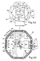
- the top of the upper box portion 42 comprises an octagonal steel box 48 having eight side panels such as 49a and 49b through which the extending members 26 of the respective probe positioners 24 can penetrate movably.
- Each panel comprises a hollow housing in which a respective sheet 50 of resilient foam, which may be similar to the above-identified gasket material, is placed. Slits such as 52 are partially cut vertically in the foam in alignment with slots 54 formed in the inner and outer surfaces of each panel housing, through which a respective extending member 26 of a respective probe positioner 24 can pass movably.
- the slitted foam permits X, Y and Z movement of the extending members 26 of each probe positioner, while maintaining the EMI, substantially hermetic, and light seal provided by the enclosure.
- the foam sheet 50 is sandwiched between a pair of steel plates 55 having slots 54 therein, such plates being slidable transversely within the panel housing through a range of movement encompassed by larger slots 56 in the inner and outer surfaces of the panel housing.
- a circular viewing aperture 58 is provided, having a recessed circular transparent sealing window 60 therein.
- a bracket 62 holds an apertured sliding shutter 64 to selectively permit or prevent the passage of light through the window.
- a stereoscope (not shown) connected to a CRT monitor can be placed above the window to provide a magnified display of the wafer or other test device and the probe tip for proper probe placement during set-up or operation.
- the window 60 can be removed and a microscope lens (not shown) surrounded by a foam gasket can be inserted through the viewing aperture 58 with the foam providing EMI, hermetic and light sealing.
- the upper box portion 42 of the environment control enclosure also includes a hinged steel door 68 which pivots outwardly about the pivot axis of a hinge 70 as shown in FIG. 2A.
- the hinge biases the door downwardly toward the top of the upper box portion 42 so that it forms a tight, overlapping, sliding peripheral seal 68a with the top of the upper box portion.
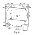
- the sealing integrity of the enclosure is likewise maintained throughout positioning movements by the motorized positioner 16 due to the provision of a series of four sealing plates 72, 74, 76 and 78 stacked slidably atop one another.
- the sizes of the plates progress increasingly from the top to the bottom one, as do the respective sizes of the central apertures 72a, 74a, 76a and 78a formed in the respective plates 72, 74, 76 and 78, and the aperture 79a formed in the bottom 44a of the lower box portion 44.
- the central aperture 72a in the top plate 72 mates closely around the bearing housing 18a of the vertically-movable plunger 18.
- the next plate in the downward progression, plate 74 has an upwardly-projecting peripheral margin 74b which limits the extent to which the plate 72 can slide across the top of the plate 74.
- the central aperture 74a in the plate 74 is of a size to permit the positioner 16 to move the plunger 18 and its bearing housing 18a transversely along the X and Y axes until the edge of the top plate 72 abuts against the margin 74b of the plate 74.
- the size of the aperture 74a is, however, too small to be uncovered by the top plate 72 when such abutment occurs, and therefore a seal is maintained between the plates 72 and 74 regardless of the movement of the plunger 18 and its bearing housing along the X and Y axes.
- This combination of sliding plates and central apertures of progressively increasing size permits a full range of movement of the plunger 18 along the X and Y axes by the positioner 16, while maintaining the enclosure in a sealed condition despite such positioning movement.
- the EMI sealing provided by this structure is effective even with respect to the electric motors of the positioner 16, since they are located below the sliding plates.
- the chuck assembly 20 is of a unique modular construction usable either with or without an environment control enclosure.
- the plunger 18 supports an adjustment plate 81 which in turn supports a rectangular stage 83 which detachably mounts a circular wafer chuck 80 of conventional design by means of screws such as 87. Shims such as 85 providing leveling.
- the wafer chuck 80 has a planar upwardly-facing wafer-supporting surface 82 having an array of vertical apertures 84 therein. These apertures communicate with respective chambers separated by O-rings 88, the chambers in turn being connected separately to different vacuum lines 90a, 90b, 90c communicating through separately-controlled vacuum valves (not shown) with a source of vacuum.
- the respective vacuum lines selectively connect the respective chambers and their apertures to the source of vacuum to hold the wafer, or alternatively isolate the apertures from the source of vacuum to release the wafer, in a conventional manner.
- the separate operability of the respective chambers and their corresponding apertures enables the chuck to hold wafers of different diameters.
- auxiliary chucks such as 92 and 94 are detachably mounted on the corners of the stage 83 by screws such as 96 independently of the wafer chuck 80.
- Each auxiliary chuck 92, 94 has its own separate upwardly-facing planar surface 100, 102 respectively, in parallel relationship to the surface 82 of the wafer chuck 80.
- Vacuum apertures 104 protrude through the surfaces 100 and 102 from communication with respective chambers 106, 108 within the body of each auxiliary chuck.
- Each of these chambers in turn communicates through a separate vacuum line 110 and a separate independently-actuated vacuum valve 114 with a source of vacuum 118 as shown schematically in FIG. 3.
- Each of the valves 114 selectively connects or isolates a respective chamber 106 or 108 with respect to the source of vacuum independently of the operation of the apertures 84 of the wafer chuck 80, so as to selectively hold or release a contact substrate or calibration substrate located on the respective surfaces 100 and 102 of the auxiliary chucks independently of the wafer.
- auxiliary chuck shims such as 120 can be inserted between the stage 83 and the auxiliary chuck to adjust the elevation of the auxiliary chuck's upper surface relative to that of the wafer chuck 80 and the otherauxiliary chuck(s). This compensates for any differences in' thicknesses between the wafer, contact substrate and calibration substrate which are simultaneously carried by the chuck assembly 20, so that the probes are easily transferable from one to the other without differences in contact pressure or the threat of damage to the probe tips.
- the vacuum valves 114 of the respective auxiliary chucks are located remotely from the chucks, and preferably exterior of the enclosure as indicated schematically in FIG. 3 to enable control of the auxiliary chucks despite the impediment to access created by the enclosure.
- This enables use of auxiliary chucks compatibly with such an enclosure, which is particularly critical because the presence of the auxiliary chucks eliminates the need for repetitive unloading and loading of contact substrates and calibration substrates during set-up and calibration, and thus eliminates the attendant need for repetitive and time-consuming purging of the environment control enclosure.
- the modular, detachably interconnected chuck assembly is also particularly advantageous when combined with a controlled-environment probe station because of the need for interchangeability of the numerous different types of wafer chucks usable with such a probe station.
Landscapes
- Engineering & Computer Science (AREA)
- Physics & Mathematics (AREA)
- Condensed Matter Physics & Semiconductors (AREA)
- General Physics & Mathematics (AREA)
- Manufacturing & Machinery (AREA)
- Computer Hardware Design (AREA)
- Microelectronics & Electronic Packaging (AREA)
- Power Engineering (AREA)
- Testing Or Measuring Of Semiconductors Or The Like (AREA)
- Container, Conveyance, Adherence, Positioning, Of Wafer (AREA)
- Testing Of Individual Semiconductor Devices (AREA)
Claims (17)
- Prüfstation mit einer im wesentlichen ebenen Fläche (82) zum Halten einer Prüfeinrichtung auf der Fläche (82), einer Halteeinrichtung (28) für einen elektrischen Messfühler (30) zum Kontaktieren der Prüfeinrichtung, einem Paar Positioniermechanismen (16, 24) zum selektiven Bewegen sowohl der Oberfläche (82) als auch der Halteeinrichtung (28) unabhängig voneinander und aufeinander zu oder voneinander weg, wobei einer der Positioniermechanismen eine X-Y-Bewegung der Oberfläche vorsieht, einem kompakten Gehäuse (12, 42, 44), welches die Oberfläche (82) umgibt und eine geschützte Umgebung schafft, deren Integrität trotz der durch die Positioniermechanismen (16, 24) herbeigeführten Bewegung sowohl der Oberfläche (82) als auch der Halteeinrichtung (28) aufeinander zu oder voneinander weg entlang einer Heranführungsachse in der Z-Richtung und trotz der vorgenannten X-Y-Bewegung der Oberfläche beibehalten wird, wobei diese Bewegung in dem Gehäuse stattfindet, wobei jeder einzelne des Paars von Positioniermechanismen wenigstens teilweise außerhalb des Gehäuses (12, 42, 44) angeordnet ist und sich zwischen dem Außenraum und dem Innenraum des Gehäuses (12, 42, 44) erstreckt, wobei das Gehäuse (12, 42, 44) einschließlich des oberen Teils (42) eine Platte, die sich seitlich oberhalb der der Fläche (82) erstreckt, sowie eine Seitenwandung einschließt, die an der Platte und die Oberfläche (82) seitlich umgibt.
- Prüfstation nach Anspruch 1, dadurch gekennzeichnet, dass das Gehäuse einen im Wesentlichen hermetischen Abschluss um die Oberfläche herbeiführt.
- Prüfstation nach Anspruch 1, dadurch gekennzeichnet, dass das Gehäuse eine Abschirmung gegen elektromagnetische Störeinflüsse schafft.
- Prüfstation nach Anspruch 1, dadurch gekennzeichnet, dass das Gehäuse (12, 42, 44) mehrere elastische, jeweils mit einer Öffnung (52) versehene Schichten (50) zum Beibehalten einer umgebungsgeschützten Integrität um die Oberfläche (82) trotz einer Bewegung der Halteeinrichtung (28) hin zu oder weg von der Oberfläche (82) durch den Positioniermechanismus (24) aufweist, wobei der Positioniermechanismus (24) einen Körper (26) umfasst, welcher sich bewegbar zwischen der äußeren Umgebung und dem Innenraum des Gehäuses (12, 42, 44) durch eine der Öffnungen (52) erstreckt und in bezug auf das Gehäuse (12, 42, 44) ohne ein Verletzen der Integrität der geschützten Umgebung bewegbar ist.
- Prüfstation nach Anspruch 4, dadurch gekennzeichnet, dass das Gehäuse (12, 42, 44) wenigstens eine abdichtende Platte (55) aufweist, die in bezug auf den Rest des Gehäuses (12, 42, 44) bewegbar ist und durch die sich der Körper (26) hindurcherstreckt, wobei eine der elastischen Schichten (50) auf der abdichtenden Platte (55) angebracht ist und sich zusammen mit der Platte in bezug auf den Rest des Gehäuses (12, 42, 44) bewegt.
- Prüfstation nach Anspruch 5, dadurch gekennzeichnet, dass die abdichtende Platte (55) gleitend in bezug auf den Rest des Gehäuses (12, 42, 44) bewegbar ist.
- Prüfstation nach Anspruch 1, gekennzeichnet durch eine Plattform (12) welche eine Vielzahl von Halteeinrichtungen (28) und einen dritten Positioniermechanismus (14a, 14b, 14c, 14d) zum selektiven Bewegen der Plattform (12) und dadurch zum gemeinsamen Bewegen der Vielzahl von Halteeinrichtungen (28) hin oder weg von der Testeinrichtung trägt.
- Prüfstation nach Anspruch 7, dadurch gekennzeichnet, dass die mehreren Halteeinrichtungen (28) unabhängig voneinander auf der Plattform (12) bewegbar angebracht und somit getrennt zur Testeinrichtung oder weg von dieser bewegbar sind.
- Prüfstation nach Anspruch 7, dadurch gekennzeichnet, dass sämtliche Positioniermechanismen (14, 24, 14a, 14b, 14c, 14d) wenigstens teilweise außerhalb des Gehäuses (12, 42, 44) angeordnet sind.
- Prüfstation nach Anspruch 1, dadurch gekennzeichnet, dass das Gehäuse (12, 42, 44) mehrere in Bezug zueinander und in Bezug auf den Rest des Gehäuses (12, 42, 44) verschiebbare Platten (72, 74, 76, 78) aufweist, wobei jede Platte (72, 74, 76, 78) und jede der Öffnungen (72a, 74a, 76a, 78a) unterschiedliche Größen aufweisen und der Positioniermechanismus (16) zum Bewegen der Oberfläche (82) einen Körper (18) aufweist, welcher sich durch die Öffnungen (72a, 74a, 76a, 78a) in den Platten (72, 74, 76, 78) zwischen der Außenseite und dem Innenraum des Gehäuses (12, 42, 44) hindurcherstreckt und in der X-Y-Richtung relativ zum Gehäuse (12, 42, 44) bewegbar ist.
- Prüfstation nach Anspruch 1, dadurch gekennzeichnet, dass der obere Kastenabschnitt (42) in einer vertikalen Richtung relativ zu einem unteren Kastenabschnitt (44) bewegbar ist, während dessen eine Abdichtung um die Oberfläche beibehalten bleibt.
- Prüfstation nach Anspruch 2, dadurch gekennzeichnet, dass das Gehäuse eine Abschirmung gegen Licht bietet.
- Prüfstation nach Anspruch 1, dadurch gekennzeichnet, dass das Gehäuse (12, 42, 44) eine Öffnung zum Schaffen eines Zugangs zu der Oberfläche (82), um zu ermöglichen, mehrere unterschiedliche Testeinrichtungen durch die Öffnung auf der Oberfläche anzuordnen, und eine Tür (68) zum selektiven Schließen der Öffnung aufweist, wobei jeder Positioniermechanismus (16, 24) eine mechanisch überführende Bewegung zu der entsprechenden eine Oberfläche und dem Halter durchführen kann, während die Tür geschlossen ist.
- Prüfstation nach Anspruch 11, dadurch gekennzeichnet, dass die Halteeinrichtung (28) durch ihren jeweiligen Positioniermechanismus (24) sowohl hin zu dem oberen Abschnitt (42) als auch weg von diesem sowie seitlich in Bezug auf diesen bewegbar ist.
- Prüfstation nach Anspruch 11, gekennzeichnet durch eine weitere Halteeinrichtung (28) für einen weiteren elektrischen Messfühler (30) und einen weiteren Positioniermechanismus (14a, 14b, 14c, 14d), wobei jede Halteeinrichtung (28) durch den oberen Abschnitt (42) des Gehäuses abgestützt ist und der obere Abschnitt (42) durch den weiteren Positioniermechanismus bewegbar ist, um beide Halteeinrichtungen (28) im Einklang miteinander zu bewegen.
- Prüfstation nach Anspruch 1, gekennzeichnet durch eine weitere Halteeinrichtung (28) für einen weiteren elektrischen Messfühler (30) und einen weiteren Positioniermechanismus (24) zum Bewegen der weiteren Halteeinrichtung (28), wobei de obere Abschnitt (42) des Gehäuses wenigstens ein Paar von Öffnungen (52) jeweils zum separaten Aufnehmen des Einsatzes eines jeweiligen mechanischen Körpers (26) von einem jeweiligen Positioniermechanismus (24) in das Gehäuse zum Bewegen eines jeweiligen elektrischen Messfühlers (30) festlegt.
- Verwendung einer Prüfstation nach einem der vorhergehenden Ansprüche zum Prüfen einer Testeinrichtung.
Applications Claiming Priority (2)
| Application Number | Priority Date | Filing Date | Title |
|---|---|---|---|
| US07/891,232 US5266889A (en) | 1992-05-29 | 1992-05-29 | Wafer probe station with integrated environment control enclosure |
| US891232 | 1992-05-29 |
Publications (3)
| Publication Number | Publication Date |
|---|---|
| EP0573183A1 EP0573183A1 (de) | 1993-12-08 |
| EP0573183B1 EP0573183B1 (de) | 1999-01-07 |
| EP0573183B2 true EP0573183B2 (de) | 2004-03-03 |
Family
ID=25397826
Family Applications (1)
| Application Number | Title | Priority Date | Filing Date |
|---|---|---|---|
| EP93303937A Expired - Lifetime EP0573183B2 (de) | 1992-05-29 | 1993-05-20 | Prüfstation mit integrierter Umgebungskontroleinrichtung |
Country Status (4)
| Country | Link |
|---|---|
| US (1) | US5266889A (de) |
| EP (1) | EP0573183B2 (de) |
| JP (1) | JP3251098B2 (de) |
| DE (1) | DE69322904T3 (de) |
Cited By (20)
| Publication number | Priority date | Publication date | Assignee | Title |
|---|---|---|---|---|
| US7138810B2 (en) | 2002-11-08 | 2006-11-21 | Cascade Microtech, Inc. | Probe station with low noise characteristics |
| US7138813B2 (en) | 1999-06-30 | 2006-11-21 | Cascade Microtech, Inc. | Probe station thermal chuck with shielding for capacitive current |
| US7164279B2 (en) | 1995-04-14 | 2007-01-16 | Cascade Microtech, Inc. | System for evaluating probing networks |
| US7176705B2 (en) | 2004-06-07 | 2007-02-13 | Cascade Microtech, Inc. | Thermal optical chuck |
| US7221172B2 (en) | 2003-05-06 | 2007-05-22 | Cascade Microtech, Inc. | Switched suspended conductor and connection |
| US7221146B2 (en) | 2002-12-13 | 2007-05-22 | Cascade Microtech, Inc. | Guarded tub enclosure |
| US7250779B2 (en) | 2002-11-25 | 2007-07-31 | Cascade Microtech, Inc. | Probe station with low inductance path |
| US7330041B2 (en) | 2004-06-14 | 2008-02-12 | Cascade Microtech, Inc. | Localizing a temperature of a device for testing |
| US7348787B2 (en) | 1992-06-11 | 2008-03-25 | Cascade Microtech, Inc. | Wafer probe station having environment control enclosure |
| US7352168B2 (en) | 2000-09-05 | 2008-04-01 | Cascade Microtech, Inc. | Chuck for holding a device under test |
| US7362115B2 (en) | 2003-12-24 | 2008-04-22 | Cascade Microtech, Inc. | Chuck with integrated wafer support |
| US7368925B2 (en) | 2002-01-25 | 2008-05-06 | Cascade Microtech, Inc. | Probe station with two platens |
| US7436170B2 (en) | 1997-06-06 | 2008-10-14 | Cascade Microtech, Inc. | Probe station having multiple enclosures |
| US7492147B2 (en) | 1992-06-11 | 2009-02-17 | Cascade Microtech, Inc. | Wafer probe station having a skirting component |
| US7492172B2 (en) | 2003-05-23 | 2009-02-17 | Cascade Microtech, Inc. | Chuck for holding a device under test |
| US7535247B2 (en) | 2005-01-31 | 2009-05-19 | Cascade Microtech, Inc. | Interface for testing semiconductors |
| US7554322B2 (en) | 2000-09-05 | 2009-06-30 | Cascade Microtech, Inc. | Probe station |
| US7656172B2 (en) | 2005-01-31 | 2010-02-02 | Cascade Microtech, Inc. | System for testing semiconductors |
| US8069491B2 (en) | 2003-10-22 | 2011-11-29 | Cascade Microtech, Inc. | Probe testing structure |
| US8319503B2 (en) | 2008-11-24 | 2012-11-27 | Cascade Microtech, Inc. | Test apparatus for measuring a characteristic of a device under test |
Families Citing this family (56)
| Publication number | Priority date | Publication date | Assignee | Title |
|---|---|---|---|---|
| US5829128A (en) | 1993-11-16 | 1998-11-03 | Formfactor, Inc. | Method of mounting resilient contact structures to semiconductor devices |
| US5476211A (en) | 1993-11-16 | 1995-12-19 | Form Factor, Inc. | Method of manufacturing electrical contacts, using a sacrificial member |
| US6313649B2 (en) * | 1992-06-11 | 2001-11-06 | Cascade Microtech, Inc. | Wafer probe station having environment control enclosure |
| JPH0653299A (ja) * | 1992-07-31 | 1994-02-25 | Tokyo Electron Yamanashi Kk | バーンイン装置 |
| US20020053734A1 (en) | 1993-11-16 | 2002-05-09 | Formfactor, Inc. | Probe card assembly and kit, and methods of making same |
| US5611946A (en) * | 1994-02-18 | 1997-03-18 | New Wave Research | Multi-wavelength laser system, probe station and laser cutter system using the same |
| DE9408512U1 (de) * | 1994-05-24 | 1995-09-21 | Höflschweiger, Nikolaus, 85408 Gammelsdorf | Teststation |
| US5835997A (en) * | 1995-03-28 | 1998-11-10 | University Of South Florida | Wafer shielding chamber for probe station |
| US6232789B1 (en) | 1997-05-28 | 2001-05-15 | Cascade Microtech, Inc. | Probe holder for low current measurements |
| US5610529A (en) * | 1995-04-28 | 1997-03-11 | Cascade Microtech, Inc. | Probe station having conductive coating added to thermal chuck insulator |
| US5914613A (en) | 1996-08-08 | 1999-06-22 | Cascade Microtech, Inc. | Membrane probing system with local contact scrub |
| DE19638816B4 (de) * | 1996-09-20 | 2009-04-30 | Karl Suss Dresden Gmbh | Tester für Halbleiteranordnungen mit einer mehrere voneinander isolierte Teile aufweisenden Spannvorrichtung |
| US5783835A (en) * | 1997-03-17 | 1998-07-21 | Probing Solutions, Incorporated | Probing with backside emission microscopy |
| US5963027A (en) * | 1997-06-06 | 1999-10-05 | Cascade Microtech, Inc. | Probe station having environment control chambers with orthogonally flexible lateral wall assembly |
| US6573702B2 (en) | 1997-09-12 | 2003-06-03 | New Wave Research | Method and apparatus for cleaning electronic test contacts |
| US6256882B1 (en) | 1998-07-14 | 2001-07-10 | Cascade Microtech, Inc. | Membrane probing system |
| US6578264B1 (en) | 1999-06-04 | 2003-06-17 | Cascade Microtech, Inc. | Method for constructing a membrane probe using a depression |
| US6838890B2 (en) * | 2000-02-25 | 2005-01-04 | Cascade Microtech, Inc. | Membrane probing system |
| US6700397B2 (en) * | 2000-07-13 | 2004-03-02 | The Micromanipulator Company, Inc. | Triaxial probe assembly |
| US6424141B1 (en) | 2000-07-13 | 2002-07-23 | The Micromanipulator Company, Inc. | Wafer probe station |
| DE20114544U1 (de) | 2000-12-04 | 2002-02-21 | Cascade Microtech, Inc., Beaverton, Oreg. | Wafersonde |
| AU2002327490A1 (en) | 2001-08-21 | 2003-06-30 | Cascade Microtech, Inc. | Membrane probing system |
| US6836135B2 (en) * | 2001-08-31 | 2004-12-28 | Cascade Microtech, Inc. | Optical testing device |
| US6951846B2 (en) * | 2002-03-07 | 2005-10-04 | The United States Of America As Represented By The Secretary Of The Army | Artemisinins with improved stability and bioavailability for therapeutic drug development and application |
| EP1509776A4 (de) | 2002-05-23 | 2010-08-18 | Cascade Microtech Inc | Sonde zum testen einer zu testenden einrichtung |
| US7046025B2 (en) * | 2002-10-02 | 2006-05-16 | Suss Microtec Testsystems Gmbh | Test apparatus for testing substrates at low temperatures |
| US6724205B1 (en) | 2002-11-13 | 2004-04-20 | Cascade Microtech, Inc. | Probe for combined signals |
| US7657110B2 (en) * | 2003-01-21 | 2010-02-02 | Sharp Laboratories Of America, Inc. | Image compression using a color visual model |
| US7057404B2 (en) | 2003-05-23 | 2006-06-06 | Sharp Laboratories Of America, Inc. | Shielded probe for testing a device under test |
| US7026806B2 (en) * | 2003-06-30 | 2006-04-11 | International Business Machines Corporation | Apparatus for preventing cross talk and interference in semiconductor devices during test |
| WO2006017078A2 (en) | 2004-07-07 | 2006-02-16 | Cascade Microtech, Inc. | Probe head having a membrane suspended probe |
| JP4142553B2 (ja) * | 2003-10-31 | 2008-09-03 | 東京エレクトロン株式会社 | 被処理体を載置するための載置台 |
| JP2005156253A (ja) | 2003-11-21 | 2005-06-16 | Agilent Technol Inc | 表示パネル試験用プローバ及び試験装置 |
| DE112004002554T5 (de) | 2003-12-24 | 2006-11-23 | Cascade Microtech, Inc., Beaverton | Active wafer probe |
| DE202005021435U1 (de) | 2004-09-13 | 2008-02-28 | Cascade Microtech, Inc., Beaverton | Doppelseitige Prüfaufbauten |
| US7034563B1 (en) * | 2005-01-26 | 2006-04-25 | Ahbee 2, L.P., A California Limited Partnership | Apparatus for measuring of thin dielectric layer properties on semiconductor wafers with contact self aligning electrodes |
| JP2006258490A (ja) * | 2005-03-15 | 2006-09-28 | Agilent Technol Inc | テストシステム及びその接続箱 |
| US7449899B2 (en) | 2005-06-08 | 2008-11-11 | Cascade Microtech, Inc. | Probe for high frequency signals |
| US20070294047A1 (en) * | 2005-06-11 | 2007-12-20 | Leonard Hayden | Calibration system |
| WO2006137979A2 (en) | 2005-06-13 | 2006-12-28 | Cascade Microtech, Inc. | Wideband active-passive differential signal probe |
| CN101680929B (zh) * | 2006-05-01 | 2012-10-10 | 瓦福默控股有限公司 | 集成电路探测卡分析器 |
| DE112007001399T5 (de) | 2006-06-09 | 2009-05-07 | Cascade Microtech, Inc., Beaverton | Messfühler für differentielle Signale mit integrierter Symmetrieschaltung |
| US7723999B2 (en) | 2006-06-12 | 2010-05-25 | Cascade Microtech, Inc. | Calibration structures for differential signal probing |
| US7443186B2 (en) | 2006-06-12 | 2008-10-28 | Cascade Microtech, Inc. | On-wafer test structures for differential signals |
| US7403028B2 (en) | 2006-06-12 | 2008-07-22 | Cascade Microtech, Inc. | Test structure and probe for differential signals |
| US7764072B2 (en) | 2006-06-12 | 2010-07-27 | Cascade Microtech, Inc. | Differential signal probing system |
| US7876114B2 (en) | 2007-08-08 | 2011-01-25 | Cascade Microtech, Inc. | Differential waveguide probe |
| US7888957B2 (en) | 2008-10-06 | 2011-02-15 | Cascade Microtech, Inc. | Probing apparatus with impedance optimized interface |
| US8410806B2 (en) | 2008-11-21 | 2013-04-02 | Cascade Microtech, Inc. | Replaceable coupon for a probing apparatus |
| JP5405575B2 (ja) * | 2010-08-31 | 2014-02-05 | 株式会社アドバンテスト | 半導体ウェハ試験装置及び半導体ウェハの試験方法 |
| US20130014983A1 (en) * | 2011-07-14 | 2013-01-17 | Texas Instruments Incorporated | Device contactor with integrated rf shield |
| CN103543298B (zh) * | 2012-07-13 | 2016-03-23 | 旺矽科技股份有限公司 | 探针固持结构及其光学检测装置 |
| US9784763B1 (en) | 2016-04-08 | 2017-10-10 | Cascade Microtech, Inc. | Shielded probe systems with controlled testing environments |
| US10698002B2 (en) | 2017-10-02 | 2020-06-30 | Formfactor Beaverton, Inc. | Probe systems for testing a device under test |
| CN113495178B (zh) * | 2020-04-07 | 2024-11-15 | 迪科特测试科技(苏州)有限公司 | 用于探测系统的屏蔽 |
| US12092658B2 (en) * | 2021-08-18 | 2024-09-17 | Mpi Corporation | Optical detection system and alignment method for a predetermined target object |
Family Cites Families (5)
| Publication number | Priority date | Publication date | Assignee | Title |
|---|---|---|---|---|
| US3333274A (en) * | 1965-04-21 | 1967-07-25 | Micro Tech Mfg Inc | Testing device |
| US3710251A (en) * | 1971-04-07 | 1973-01-09 | Collins Radio Co | Microelectric heat exchanger pedestal |
| US4115736A (en) * | 1977-03-09 | 1978-09-19 | The United States Of America As Represented By The Secretary Of The Air Force | Probe station |
| JPS5953659B2 (ja) * | 1980-04-11 | 1984-12-26 | 株式会社日立製作所 | 真空室中回転体の往復動機構 |
| US5077523A (en) * | 1989-11-03 | 1991-12-31 | John H. Blanz Company, Inc. | Cryogenic probe station having movable chuck accomodating variable thickness probe cards |
-
1992
- 1992-05-29 US US07/891,232 patent/US5266889A/en not_active Expired - Lifetime
-
1993
- 1993-05-20 DE DE69322904T patent/DE69322904T3/de not_active Expired - Lifetime
- 1993-05-20 EP EP93303937A patent/EP0573183B2/de not_active Expired - Lifetime
- 1993-05-31 JP JP12926693A patent/JP3251098B2/ja not_active Expired - Fee Related
Cited By (39)
| Publication number | Priority date | Publication date | Assignee | Title |
|---|---|---|---|---|
| US7595632B2 (en) | 1992-06-11 | 2009-09-29 | Cascade Microtech, Inc. | Wafer probe station having environment control enclosure |
| US7492147B2 (en) | 1992-06-11 | 2009-02-17 | Cascade Microtech, Inc. | Wafer probe station having a skirting component |
| US7589518B2 (en) | 1992-06-11 | 2009-09-15 | Cascade Microtech, Inc. | Wafer probe station having a skirting component |
| US7348787B2 (en) | 1992-06-11 | 2008-03-25 | Cascade Microtech, Inc. | Wafer probe station having environment control enclosure |
| US7321233B2 (en) | 1995-04-14 | 2008-01-22 | Cascade Microtech, Inc. | System for evaluating probing networks |
| US7164279B2 (en) | 1995-04-14 | 2007-01-16 | Cascade Microtech, Inc. | System for evaluating probing networks |
| US7626379B2 (en) | 1997-06-06 | 2009-12-01 | Cascade Microtech, Inc. | Probe station having multiple enclosures |
| US7436170B2 (en) | 1997-06-06 | 2008-10-14 | Cascade Microtech, Inc. | Probe station having multiple enclosures |
| US7616017B2 (en) | 1999-06-30 | 2009-11-10 | Cascade Microtech, Inc. | Probe station thermal chuck with shielding for capacitive current |
| US7292057B2 (en) | 1999-06-30 | 2007-11-06 | Cascade Microtech, Inc. | Probe station thermal chuck with shielding for capacitive current |
| US7138813B2 (en) | 1999-06-30 | 2006-11-21 | Cascade Microtech, Inc. | Probe station thermal chuck with shielding for capacitive current |
| US7352168B2 (en) | 2000-09-05 | 2008-04-01 | Cascade Microtech, Inc. | Chuck for holding a device under test |
| US7501810B2 (en) | 2000-09-05 | 2009-03-10 | Cascade Microtech, Inc. | Chuck for holding a device under test |
| US7688062B2 (en) | 2000-09-05 | 2010-03-30 | Cascade Microtech, Inc. | Probe station |
| US7423419B2 (en) | 2000-09-05 | 2008-09-09 | Cascade Microtech, Inc. | Chuck for holding a device under test |
| US7969173B2 (en) | 2000-09-05 | 2011-06-28 | Cascade Microtech, Inc. | Chuck for holding a device under test |
| US7518358B2 (en) | 2000-09-05 | 2009-04-14 | Cascade Microtech, Inc. | Chuck for holding a device under test |
| US7554322B2 (en) | 2000-09-05 | 2009-06-30 | Cascade Microtech, Inc. | Probe station |
| US7514915B2 (en) | 2000-09-05 | 2009-04-07 | Cascade Microtech, Inc. | Chuck for holding a device under test |
| US7368925B2 (en) | 2002-01-25 | 2008-05-06 | Cascade Microtech, Inc. | Probe station with two platens |
| US7295025B2 (en) | 2002-11-08 | 2007-11-13 | Cascade Microtech, Inc. | Probe station with low noise characteristics |
| US7138810B2 (en) | 2002-11-08 | 2006-11-21 | Cascade Microtech, Inc. | Probe station with low noise characteristics |
| US7250779B2 (en) | 2002-11-25 | 2007-07-31 | Cascade Microtech, Inc. | Probe station with low inductance path |
| US7639003B2 (en) | 2002-12-13 | 2009-12-29 | Cascade Microtech, Inc. | Guarded tub enclosure |
| US7221146B2 (en) | 2002-12-13 | 2007-05-22 | Cascade Microtech, Inc. | Guarded tub enclosure |
| US7468609B2 (en) | 2003-05-06 | 2008-12-23 | Cascade Microtech, Inc. | Switched suspended conductor and connection |
| US7221172B2 (en) | 2003-05-06 | 2007-05-22 | Cascade Microtech, Inc. | Switched suspended conductor and connection |
| US7492172B2 (en) | 2003-05-23 | 2009-02-17 | Cascade Microtech, Inc. | Chuck for holding a device under test |
| US8069491B2 (en) | 2003-10-22 | 2011-11-29 | Cascade Microtech, Inc. | Probe testing structure |
| US7688091B2 (en) | 2003-12-24 | 2010-03-30 | Cascade Microtech, Inc. | Chuck with integrated wafer support |
| US7362115B2 (en) | 2003-12-24 | 2008-04-22 | Cascade Microtech, Inc. | Chuck with integrated wafer support |
| US7504823B2 (en) | 2004-06-07 | 2009-03-17 | Cascade Microtech, Inc. | Thermal optical chuck |
| US7176705B2 (en) | 2004-06-07 | 2007-02-13 | Cascade Microtech, Inc. | Thermal optical chuck |
| US7330041B2 (en) | 2004-06-14 | 2008-02-12 | Cascade Microtech, Inc. | Localizing a temperature of a device for testing |
| US7535247B2 (en) | 2005-01-31 | 2009-05-19 | Cascade Microtech, Inc. | Interface for testing semiconductors |
| US7656172B2 (en) | 2005-01-31 | 2010-02-02 | Cascade Microtech, Inc. | System for testing semiconductors |
| US7898281B2 (en) | 2005-01-31 | 2011-03-01 | Cascade Mircotech, Inc. | Interface for testing semiconductors |
| US7940069B2 (en) | 2005-01-31 | 2011-05-10 | Cascade Microtech, Inc. | System for testing semiconductors |
| US8319503B2 (en) | 2008-11-24 | 2012-11-27 | Cascade Microtech, Inc. | Test apparatus for measuring a characteristic of a device under test |
Also Published As
| Publication number | Publication date |
|---|---|
| JP3251098B2 (ja) | 2002-01-28 |
| US5266889A (en) | 1993-11-30 |
| DE69322904D1 (de) | 1999-02-18 |
| JPH0653297A (ja) | 1994-02-25 |
| DE69322904T2 (de) | 1999-05-27 |
| EP0573183A1 (de) | 1993-12-08 |
| DE69322904T3 (de) | 2004-08-19 |
| EP0573183B1 (de) | 1999-01-07 |
Similar Documents
| Publication | Publication Date | Title |
|---|---|---|
| EP0573183B2 (de) | Prüfstation mit integrierter Umgebungskontroleinrichtung | |
| EP0572180B1 (de) | Wafer Prüfstation mit Zusatzhaltetischen | |
| US6486687B2 (en) | Wafer probe station having environment control enclosure | |
| US6313649B2 (en) | Wafer probe station having environment control enclosure | |
| EP0574149B1 (de) | Wafer Prüfstation mit integrierten einrichtungen für Erdung, Kelvinverbindung und Abschirmung | |
| US7501810B2 (en) | Chuck for holding a device under test | |
| US20080042670A1 (en) | Probe station |
Legal Events
| Date | Code | Title | Description |
|---|---|---|---|
| PUAI | Public reference made under article 153(3) epc to a published international application that has entered the european phase |
Free format text: ORIGINAL CODE: 0009012 |
|
| AK | Designated contracting states |
Kind code of ref document: A1 Designated state(s): DE FR GB IT |
|
| 17P | Request for examination filed |
Effective date: 19940520 |
|
| 17Q | First examination report despatched |
Effective date: 19950614 |
|
| GRAG | Despatch of communication of intention to grant |
Free format text: ORIGINAL CODE: EPIDOS AGRA |
|
| GRAG | Despatch of communication of intention to grant |
Free format text: ORIGINAL CODE: EPIDOS AGRA |
|
| GRAH | Despatch of communication of intention to grant a patent |
Free format text: ORIGINAL CODE: EPIDOS IGRA |
|
| GRAH | Despatch of communication of intention to grant a patent |
Free format text: ORIGINAL CODE: EPIDOS IGRA |
|
| GRAA | (expected) grant |
Free format text: ORIGINAL CODE: 0009210 |
|
| AK | Designated contracting states |
Kind code of ref document: B1 Designated state(s): DE FR GB IT |
|
| PG25 | Lapsed in a contracting state [announced via postgrant information from national office to epo] |
Ref country code: IT Free format text: LAPSE BECAUSE OF FAILURE TO SUBMIT A TRANSLATION OF THE DESCRIPTION OR TO PAY THE FEE WITHIN THE PRE;WARNING: LAPSES OF ITALIAN PATENTS WITH EFFECTIVE DATE BEFORE 2007 MAY HAVE OCCURRED AT ANY TIME BEFORE 2007. THE CORRECT EFFECTIVE DATE MAY BE DIFFERENT FROM THE ONE RECORDED.SCRIBED TIME-LIMIT Effective date: 19990107 Ref country code: FR Free format text: LAPSE BECAUSE OF FAILURE TO SUBMIT A TRANSLATION OF THE DESCRIPTION OR TO PAY THE FEE WITHIN THE PRESCRIBED TIME-LIMIT Effective date: 19990107 |
|
| REF | Corresponds to: |
Ref document number: 69322904 Country of ref document: DE Date of ref document: 19990218 |
|
| EN | Fr: translation not filed | ||
| PLBQ | Unpublished change to opponent data |
Free format text: ORIGINAL CODE: EPIDOS OPPO |
|
| PLBI | Opposition filed |
Free format text: ORIGINAL CODE: 0009260 |
|
| 26 | Opposition filed |
Opponent name: ERICH REITINGER-SYSTEMENTWICKLUNG UND FORSCHUNG FU Effective date: 19991007 Opponent name: KARL SUSS DRESDEN GMBH Effective date: 19991007 |
|
| PLBF | Reply of patent proprietor to notice(s) of opposition |
Free format text: ORIGINAL CODE: EPIDOS OBSO |
|
| PLBF | Reply of patent proprietor to notice(s) of opposition |
Free format text: ORIGINAL CODE: EPIDOS OBSO |
|
| PLAW | Interlocutory decision in opposition |
Free format text: ORIGINAL CODE: EPIDOS IDOP |
|
| APAC | Appeal dossier modified |
Free format text: ORIGINAL CODE: EPIDOS NOAPO |
|
| RTI2 | Title (correction) |
Free format text: PROBE STATION WITH INTEGRATED ENVIRONMENT CONTROL ENCLOSURE |
|
| APAE | Appeal reference modified |
Free format text: ORIGINAL CODE: EPIDOS REFNO |
|
| RTI2 | Title (correction) |
Free format text: PROBE STATION WITH INTEGRATED ENVIRONMENT CONTROL ENCLOSURE |
|
| APAE | Appeal reference modified |
Free format text: ORIGINAL CODE: EPIDOS REFNO |
|
| APAC | Appeal dossier modified |
Free format text: ORIGINAL CODE: EPIDOS NOAPO |
|
| APAC | Appeal dossier modified |
Free format text: ORIGINAL CODE: EPIDOS NOAPO |
|
| APAC | Appeal dossier modified |
Free format text: ORIGINAL CODE: EPIDOS NOAPO |
|
| APAC | Appeal dossier modified |
Free format text: ORIGINAL CODE: EPIDOS NOAPO |
|
| REG | Reference to a national code |
Ref country code: GB Ref legal event code: IF02 |
|
| PLAB | Opposition data, opponent's data or that of the opponent's representative modified |
Free format text: ORIGINAL CODE: 0009299OPPO |
|
| R26 | Opposition filed (corrected) |
Opponent name: ERICH REITINGER-SYSTEMENTWICKLUNG UND FORSCHUNG FU Effective date: 19991007 Opponent name: SUSS MICROTEC TEST SYSTEMS GMBH Effective date: 19991007 |
|
| APBU | Appeal procedure closed |
Free format text: ORIGINAL CODE: EPIDOSNNOA9O |
|
| APAY | Date of receipt of notice of appeal deleted |
Free format text: ORIGINAL CODE: EPIDOSDNOA2O |
|
| APBP | Date of receipt of notice of appeal recorded |
Free format text: ORIGINAL CODE: EPIDOSNNOA2O |
|
| PUAH | Patent maintained in amended form |
Free format text: ORIGINAL CODE: 0009272 |
|
| STAA | Information on the status of an ep patent application or granted ep patent |
Free format text: STATUS: PATENT MAINTAINED AS AMENDED |
|
| 27A | Patent maintained in amended form |
Effective date: 20040303 |
|
| AK | Designated contracting states |
Kind code of ref document: B2 Designated state(s): DE FR GB IT |
|
| EN | Fr: translation not filed | ||
| APAH | Appeal reference modified |
Free format text: ORIGINAL CODE: EPIDOSCREFNO |
|
| APBQ | Date of receipt of statement of grounds of appeal recorded |
Free format text: ORIGINAL CODE: EPIDOSNNOA3O |
|
| APBU | Appeal procedure closed |
Free format text: ORIGINAL CODE: EPIDOSNNOA9O |
|
| PGFP | Annual fee paid to national office [announced via postgrant information from national office to epo] |
Ref country code: GB Payment date: 20080529 Year of fee payment: 16 |
|
| GBPC | Gb: european patent ceased through non-payment of renewal fee |
Effective date: 20090520 |
|
| PG25 | Lapsed in a contracting state [announced via postgrant information from national office to epo] |
Ref country code: GB Free format text: LAPSE BECAUSE OF NON-PAYMENT OF DUE FEES Effective date: 20090520 |
|
| PGFP | Annual fee paid to national office [announced via postgrant information from national office to epo] |
Ref country code: DE Payment date: 20101130 Year of fee payment: 18 |
|
| REG | Reference to a national code |
Ref country code: DE Ref legal event code: R119 Ref document number: 69322904 Country of ref document: DE |
|
| REG | Reference to a national code |
Ref country code: DE Ref legal event code: R119 Ref document number: 69322904 Country of ref document: DE |
|
| PG25 | Lapsed in a contracting state [announced via postgrant information from national office to epo] |
Ref country code: DE Free format text: LAPSE BECAUSE OF NON-PAYMENT OF DUE FEES Effective date: 20111130 |