EP0572925A1 - Aufzeichnungskassette und Aufnahme-/Wiedergabegerät - Google Patents
Aufzeichnungskassette und Aufnahme-/Wiedergabegerät Download PDFInfo
- Publication number
- EP0572925A1 EP0572925A1 EP93108605A EP93108605A EP0572925A1 EP 0572925 A1 EP0572925 A1 EP 0572925A1 EP 93108605 A EP93108605 A EP 93108605A EP 93108605 A EP93108605 A EP 93108605A EP 0572925 A1 EP0572925 A1 EP 0572925A1
- Authority
- EP
- European Patent Office
- Prior art keywords
- recording medium
- information indicating
- medium cassette
- contacts
- cassette
- Prior art date
- Legal status (The legal status is an assumption and is not a legal conclusion. Google has not performed a legal analysis and makes no representation as to the accuracy of the status listed.)
- Granted
Links
- 238000010276 construction Methods 0.000 claims description 3
- 239000004020 conductor Substances 0.000 description 6
- 238000001514 detection method Methods 0.000 description 4
- 238000006243 chemical reaction Methods 0.000 description 3
- 238000010586 diagram Methods 0.000 description 3
- 230000000295 complement effect Effects 0.000 description 2
- 230000000994 depressogenic effect Effects 0.000 description 2
- 238000000034 method Methods 0.000 description 2
- 238000003466 welding Methods 0.000 description 2
- 239000000853 adhesive Substances 0.000 description 1
- 230000001070 adhesive effect Effects 0.000 description 1
- 238000005452 bending Methods 0.000 description 1
- 238000003780 insertion Methods 0.000 description 1
- 230000037431 insertion Effects 0.000 description 1
- 239000011810 insulating material Substances 0.000 description 1
- 229920003002 synthetic resin Polymers 0.000 description 1
- 239000000057 synthetic resin Substances 0.000 description 1
Images


Classifications
-
- H—ELECTRICITY
- H05—ELECTRIC TECHNIQUES NOT OTHERWISE PROVIDED FOR
- H05K—PRINTED CIRCUITS; CASINGS OR CONSTRUCTIONAL DETAILS OF ELECTRIC APPARATUS; MANUFACTURE OF ASSEMBLAGES OF ELECTRICAL COMPONENTS
- H05K1/00—Printed circuits
- H05K1/02—Details
- H05K1/0266—Marks, test patterns or identification means
-
- G—PHYSICS
- G11—INFORMATION STORAGE
- G11B—INFORMATION STORAGE BASED ON RELATIVE MOVEMENT BETWEEN RECORD CARRIER AND TRANSDUCER
- G11B15/00—Driving, starting or stopping record carriers of filamentary or web form; Driving both such record carriers and heads; Guiding such record carriers or containers therefor; Control thereof; Control of operating function
- G11B15/02—Control of operating function, e.g. switching from recording to reproducing
- G11B15/05—Control of operating function, e.g. switching from recording to reproducing by sensing features present on or derived from record carrier or container
- G11B15/06—Control of operating function, e.g. switching from recording to reproducing by sensing features present on or derived from record carrier or container by sensing auxiliary features on record carriers or containers, e.g. to stop machine near the end of a tape
- G11B15/07—Control of operating function, e.g. switching from recording to reproducing by sensing features present on or derived from record carrier or container by sensing auxiliary features on record carriers or containers, e.g. to stop machine near the end of a tape on containers
-
- G—PHYSICS
- G11—INFORMATION STORAGE
- G11B—INFORMATION STORAGE BASED ON RELATIVE MOVEMENT BETWEEN RECORD CARRIER AND TRANSDUCER
- G11B23/00—Record carriers not specific to the method of recording or reproducing; Accessories, e.g. containers, specially adapted for co-operation with the recording or reproducing apparatus ; Intermediate mediums; Apparatus or processes specially adapted for their manufacture
- G11B23/02—Containers; Storing means both adapted to cooperate with the recording or reproducing means
- G11B23/04—Magazines; Cassettes for webs or filaments
- G11B23/08—Magazines; Cassettes for webs or filaments for housing webs or filaments having two distinct ends
- G11B23/087—Magazines; Cassettes for webs or filaments for housing webs or filaments having two distinct ends using two different reels or cores
- G11B23/08707—Details
- G11B23/08714—Auxiliary features
-
- G—PHYSICS
- G11—INFORMATION STORAGE
- G11B—INFORMATION STORAGE BASED ON RELATIVE MOVEMENT BETWEEN RECORD CARRIER AND TRANSDUCER
- G11B23/00—Record carriers not specific to the method of recording or reproducing; Accessories, e.g. containers, specially adapted for co-operation with the recording or reproducing apparatus ; Intermediate mediums; Apparatus or processes specially adapted for their manufacture
- G11B23/30—Record carriers not specific to the method of recording or reproducing; Accessories, e.g. containers, specially adapted for co-operation with the recording or reproducing apparatus ; Intermediate mediums; Apparatus or processes specially adapted for their manufacture with provision for auxiliary signals
-
- G—PHYSICS
- G11—INFORMATION STORAGE
- G11B—INFORMATION STORAGE BASED ON RELATIVE MOVEMENT BETWEEN RECORD CARRIER AND TRANSDUCER
- G11B25/00—Apparatus characterised by the shape of record carrier employed but not specific to the method of recording or reproducing, e.g. dictating apparatus; Combinations of such apparatus
- G11B25/06—Apparatus characterised by the shape of record carrier employed but not specific to the method of recording or reproducing, e.g. dictating apparatus; Combinations of such apparatus using web-form record carriers, e.g. tape
- G11B25/066—Apparatus characterised by the shape of record carrier employed but not specific to the method of recording or reproducing, e.g. dictating apparatus; Combinations of such apparatus using web-form record carriers, e.g. tape adapted for use with containers of different sizes or configurations; adaptor devices therefor
-
- G—PHYSICS
- G11—INFORMATION STORAGE
- G11B—INFORMATION STORAGE BASED ON RELATIVE MOVEMENT BETWEEN RECORD CARRIER AND TRANSDUCER
- G11B5/00—Recording by magnetisation or demagnetisation of a record carrier; Reproducing by magnetic means; Record carriers therefor
- G11B5/74—Record carriers characterised by the form, e.g. sheet shaped to wrap around a drum
- G11B5/78—Tape carriers
-
- G—PHYSICS
- G11—INFORMATION STORAGE
- G11B—INFORMATION STORAGE BASED ON RELATIVE MOVEMENT BETWEEN RECORD CARRIER AND TRANSDUCER
- G11B5/00—Recording by magnetisation or demagnetisation of a record carrier; Reproducing by magnetic means; Record carriers therefor
- G11B5/008—Recording on, or reproducing or erasing from, magnetic tapes, sheets, e.g. cards, or wires
- G11B5/00813—Recording on, or reproducing or erasing from, magnetic tapes, sheets, e.g. cards, or wires magnetic tapes
- G11B5/00817—Recording on, or reproducing or erasing from, magnetic tapes, sheets, e.g. cards, or wires magnetic tapes on longitudinal tracks only, e.g. for serpentine format recording
- G11B5/00821—Recording on, or reproducing or erasing from, magnetic tapes, sheets, e.g. cards, or wires magnetic tapes on longitudinal tracks only, e.g. for serpentine format recording using stationary heads
-
- H—ELECTRICITY
- H05—ELECTRIC TECHNIQUES NOT OTHERWISE PROVIDED FOR
- H05K—PRINTED CIRCUITS; CASINGS OR CONSTRUCTIONAL DETAILS OF ELECTRIC APPARATUS; MANUFACTURE OF ASSEMBLAGES OF ELECTRICAL COMPONENTS
- H05K1/00—Printed circuits
- H05K1/02—Details
- H05K1/0286—Programmable, customizable or modifiable circuits
- H05K1/029—Programmable, customizable or modifiable circuits having a programmable lay-out, i.e. adapted for choosing between a few possibilities
-
- H—ELECTRICITY
- H05—ELECTRIC TECHNIQUES NOT OTHERWISE PROVIDED FOR
- H05K—PRINTED CIRCUITS; CASINGS OR CONSTRUCTIONAL DETAILS OF ELECTRIC APPARATUS; MANUFACTURE OF ASSEMBLAGES OF ELECTRICAL COMPONENTS
- H05K2201/00—Indexing scheme relating to printed circuits covered by H05K1/00
- H05K2201/10—Details of components or other objects attached to or integrated in a printed circuit board
- H05K2201/10007—Types of components
- H05K2201/10022—Non-printed resistor
-
- H—ELECTRICITY
- H05—ELECTRIC TECHNIQUES NOT OTHERWISE PROVIDED FOR
- H05K—PRINTED CIRCUITS; CASINGS OR CONSTRUCTIONAL DETAILS OF ELECTRIC APPARATUS; MANUFACTURE OF ASSEMBLAGES OF ELECTRICAL COMPONENTS
- H05K3/00—Apparatus or processes for manufacturing printed circuits
- H05K3/22—Secondary treatment of printed circuits
- H05K3/222—Completing of printed circuits by adding non-printed jumper connections
Definitions
- the present invention relates to a recording medium cassette, and to a recording and/or reproducing apparatus. More specifically, the present invention relates to a recording medium cassette capable of being optionally provided with additional identifiers and of being easily miniaturized if necessary, and having satisfactory appearance, and to a recording and/or reproducing apparatus suitable for using the same recording medium cassette.
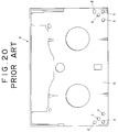
- the related-art recording medium cassette such as a tape cassette a shown in Fig. 20 for use on an 8 mm video tape recorder (hereinafter abbreviated to "VTR"), is provided with recognition holes indicating pieces of information about the magnetic tape including the type of the magnetic tape and the thickness of the magnetic tape.
- VTR video tape recorder
- the tape cassette a is provided with recognition holes c in the bottom wall b thereof in the opposite rear corners. These recognition holes c are allocated to pieces of information including the type of the magnetic tape and the thickness of the magnetic tape.
- the detecting pins of switches are inserted in the recognition holes c , respectively, to read the pieces information on the basis of the respective depths of insertion of the detecting pins in the recognition holes c .
- Fig. 20 indicated at d are positioning holes.
- the recognition holes c are either open or closed to indicate pieces of information. Accordingly, the recognition holes c need to be formed in portions of the bottom wall b of the tape cassette a having a thickness large enough to form the recognition holes c . Consequently, the recognition holes c can be formed only in limited areas of the surface of the bottom wall b and the restriction holes c diminishes the area of the surface of the bottom wall b available for other uses.
- the recognition holes need to be formed in the opposite corners of the rear side of the bottom wall, the positions of the recognition holes of a small-sized tape cassette on the VTR and those of the corresponding recognition holes of a large-sized tape cassette on the same VTR are different from each other.
- a VTR which is designed to use both the small-sized tape cassette and the large-sized tape cassette must be provided with two sets of switches, namely, one set of switches for the recognition holes of the small-sized tape cassette and another set of switches for the recognition holes of the large-sized tape cassette, or one set of switches which can be shifted according to the size of the tape cassette.
- Such an arrangement of the switches makes the construction of the VTR complex.
- each recognition hole is allocated to a single piece of information, the number of recognition holes increases with the increase of the number of pieces of information, increasing area and volume necessary for forming the recognition holes, which makes the miniaturization of the tape cassette difficult.
- recognition holes c are identified by physical items such as position and depth thereof, identifiers which are not taken into consideration when prescribing a format cannot be added.
- Recording medium cassettes provided with an IC chip for storing information about the recording medium cassettes have been proposed, for example, in: U.S.P. 4,338,644 Jul. 6, 1982 (Theophiel C.J.L. Starr) U.S.P. 4,383,285 May 10, 1983 (Theophiel C.J.L. Starr) U.S.P. 4,426,684 Jan. 17, 1984 (Claude Sechet et al.) U.S.P. 4,839,875 Jul. 13, 1989 (Zenkichi Kuriyama et al.) Although these previously proposed recording medium cassettes facilitate storing information about the recording medium cassettes, the IC chip increases the cost of the recording medium cassettes.
- a recording medium cassette capable of being optionally provided with additional information and of being formed in a relatively small size, and having satisfactory appearance.
- a second object of the present invention is to provide a recording medium cassette having an information indicating means for indicating information about the recording medium, facilitating the detection of the information.
- a third object of the present invention is to provide a recording/reproducing apparatus or a reproducing apparatus capable of using such a recording medium cassette.
- a recording medium cassette in accordance with the present invention has a case provided with a plurality of exposed information indicating contacts, and a recording/reproducing apparatus or a reproducing apparatus in accordance with the present invention is provided with a plurality of information detecting contacts respectively corresponding to the plurality of information indicating contacts of the recording medium cassette, and a power supply having an output terminal connected to one of the plurality of information detecting contacts.
- a recording medium cassette capable of being used on a compatible recording/reproducing apparatus capable of using at least two kinds of recording medium cassettes differing in size from each other is provided with information indicating means which coincides with those of another recording medium cassette of a different size when the mouth thereof coincides with that of the latter recording medium cassette.
- a recording/reproducing apparatus capable of using both recording medium cassettes differing in size from each other and of positioning those different recording medium cassettes with their mouths positioned at a fixed position therein, and provided with a fixed information detecting means capable of detecting pieces of information indicated by the information indicating contacts of either of the recording medium cassettes.
- the recording medium cassette can be miniaturized because the information indicating contacts may be formed in a relatively small size in a relatively small area.
- each information indicating contact is used for indicating a bit of a signal instead of allocating the information indicating contact to one of the identifiers identifying the category of the recording medium cassette, a comparatively large number of pieces of information can be indicated by a comparatively small number of information indicating contacts; for example, eight identifiers by three indication indicating contacts, i.e., three bits, and sixteen identifiers by four indication indicating contacts, i.e., four bits.
- Identifiers which are not taken into consideration when prescribing a format can be easily added to the format without modifying or without changing the size of the recording medium cassette, which enhances the extendibility of the format.
- the information indicating contacts do not need too many holes formed in the case of the recording medium cassette need not be provided with too many holes, the information indicating contacts do not spoil the appearance of the recording medium cassette.
- the recording/reproducing apparatus needs only a single information detecting means.
- the present invention will be described as applied to a video tape cassette and to a VTR which uses the video tape cassette.
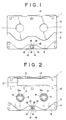
- a small-sized video tape cassette 1 has a case 2 having a laterally elongate rectangular shape and formed by joining together a top half case 3 and a bottom half case 4.
- a pair of tape reels 6 are supported for rotation within the case 2, and a magnetic tape 5 having opposite ends fastened to the pair of tape reels 6 is held on the pair of tape reels 6.
- Formed in the bottom wall 8 of the case 2 are a pair of laterally spaced through holes 7 for receiving the bosses 9 of the tape reels 6 so that splined holes 9a formed in the bosses 9 are accessible from outside.
- a shutter 10 is supported slidably on the inner surface of the bottom wall 8 of the bottom half case 4.
- the shutter 10 is provided with a pair of laterally spaced through holes 11.
- the through holes 11 thereof are dislocated from the through holes 7 of the case 2 to conceal the splined holes 9a of the tape reels 6.
- the through holes 11 thereof coincide with the through holes 7, respectively, so that the splined holes 9a of the tape reels 6 are exposed through the through holes 7 and 11.
- Tape outlets 12 are formed in the front wall of the case 2 at positions near the opposite ends of the front wall of the case 2, respectively.
- a mouth 13 opening toward the front and downward is formed between the tape outlets 12 in the front portion of the case 2.
- a portion of the magnetic tape 5 extends between the tape outlets 12 along the front side of the mouth 13.
- a turning lid 14 is supported pivotally in the front portion of the case 2 so as to cover the front side of the case 2.
- a shallow, rectangular recess 15 is formed in the inner surface of the bottom wall 8 of the case 2 at the middle of the rear portion of the bottom wall 8.
- Contact slots 16 are formed in the bottom wall 8 of the case 2 in the recess 15 in a lateral arrangement.
- a printed wiring board 17 has a rectangular shape substantially exactly fitting the recess 15.
- Rectangular contacts 18, i.e., contacts 18a, 18b, 18c and 18d in this embodiment, are formed on the lower surface of the printed wiring board 17 in a lateral arrangement so that the contacts 18 coincide with the contact slots 16 of the case 2, respectively, when the printed wiring board 17 is fitted in the recess 15.
- the contacts 18 are gold-plated to secure durability and reliability.
- a wiring pattern 19 of a conductive material is formed on the lower surface of the printed wiring board 17. In this embodiment, the contacts 18a and 18c are interconnected by the wiring pattern.
- the printed wiring board 17 is fitted in the recess 15 of the case 2 with its lower surface provided with the contacts 18a, 18b, 18c and 18d and the wiring patter 19 facing down and fixed to the bottom wall 8 with an adhesive or by welding.
- pins formed on the bottom surface of the recess 15 of the case 2 are inserted through holes formed in the printed wiring board 17, and then the protruding portions of the pins are hot-pressed.
- ribs may be formed on the inner surface of the top half case 3 so that the ribs press down the printed wiring board 17 against the bottom surface of the recess 15 when the top half case 3 and the bottom half case 4 are joined together.
- a large-sized tape cassette 20, which is larger than the small-sized tape cassette 1, is substantially the same in construction as the small-sized tape cassette 1, except that the large-sized tape cassette 20 is provided with a printed wiring board at a position different from that of the printed wiring board 17 of the small-sized tape cassette 1.
- the large-sized tape cassette 20 has a case 21 having the shape of a laterally elongate, rectangular, flat box.
- a pair of tape reels 23 are supported for rotation within the case 21, and a magnetic tape 22 is held on the tape reels 23.
- a portion of the magnetic tape 22 extends between tape outlets 24 along the front side of a mouth 25.
- Splined holes 26a formed in the bosses 26 of the reels 23 are accessible from outside through through holes 28 formed in the bottom wall 27 of the case 21, and through holes 30 formed in a shutter 29 when the shutter 29 is at its open position.
- the front side of the case 21 is covered with a lid 31.
- a shallow recess 32 is formed in the inner surface of the bottom wall 27 of the case 21 at a position slightly to the rear from the central portion of the inner surface of the bottom wall 27.
- the recess 32 is substantially the same in size and depth as the recess 15 of the small-sized tape cassette 1.
- Contact slots 33 are formed in the bottom wall 27 of the case 21 in the recess 32.
- a printed wiring board 34 which is substantially identical with the printed wiring board 17, is provided with contacts 35 and a wiring pattern 36 of a conductive material on its lower surface.
- the printed wiring board 34 is fixedly fitted in the recess 32 with its lower surface facing down and with the contacts 35 coinciding respectively with the contact slots 33.
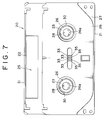
- VTR 41 As shown in Fig. 16, in which the small-sized tape cassette 1 and the large-sized tape cassette 20 are superposed hypothetically one over the other on a VTR 41 designed for using either of the small-sized tape cassette 1 or the large-sized tape cassette 20, the respective mouths 13 and 25 of the tape cassettes 1 and 20 coincide with each other. Therefore, VTR 41 needs a single set of tape operating system and the arrangement and operation of the component members of the tape operating system of the VTR 41 are simple. In Fig. 16, there are shown a magnetic head cylinder 37, a capstan 38, a pinch roller 39 and guide rollers 40.
- the VTR 41 has a cabinet 42, a mechanical chassis 43 disposed within the cabinet 42, mechanical components including the magnetic head cylinder 37 and reel tables 44 are mounted on the mechanical chassis 43, and a connector 45 fixedly disposed on the mechanical chassis 43 at a position corresponding to the contacts 18 (35).
- the reel tables 44 are shifted between positions for supporting the reels 6 of the small-sized tape cassette 1 and positions for supporting the reels 23 of the large-sized tape cassette 20.
- the connector 45 comprises a casing 46, detecting contacts 56 and a shaft pivotally supporting the detecting contacts 56 on the casing 46.
- the casing 46 is formed of an insulating material, such as a synthetic resin, and is provided with a recess 47 opening upward and backward.
- Grooves 48 are formed in the front portion of the bottom surface of the recess 47 to form an overhang 49 at the front end of the recess 47.
- Support walls 50 are arranged laterally at regular intervals along the rear end of the recess 47 to form spaces 51 therebetween and the side walls of the recess 47 and the support walls 50.
- Positioning recesses 52 are formed in the overhang 49 at positions respectively corresponding to the spaces 51.
- An attaching lug 53 provided with a through hole 53a projects from the middle of the front end of the casing 46, and a positioning lug 54 provided with a recess 54a opening rearward projects rearward from the meddle of the rear end of the casing 46.
- Through holes 55 are formed in the lower wall of the casing 46 at positions between the spaces 51 and the positioning recesses 52, respectively.
- the detecting contacts 56 are formed by bending a conductive spring wire in the shape of a torsion coil spring. Each detecting contact 56 has a coil portion 57, a lower arm 58 and an upper arm 59. The free end of the lower arm 58 is bent down at right angles to form a connecting end 58a. The front portions of the upper arms 59 are bent down in the shape of an inverted letter V to form contact portions 59a. The extremities 59b of the upper arms 59 extend substantially horizontally.
- the coil portions 57 of the detecting contacts 56 are fitted in the spaces 51 of the casing 46 with the lower arms 58 extended along the bottom surface of the recess 47 of the casing 46 and the extremities of the connecting portions 58a projecting downward from the bottom surface of the casing 46.
- the extremities of the contact portions 59a of the upper arms 59 are vertically movable in the positioning recess 52.
- the extremities 59b of the upper arms 59 underlie portions of the lower surface of the overhang 49 in front of the front ends of the positioning recess 52. Since the coil portions 57 are held in place and the upper arms 59 tend to turn upward when not depressed, the extremities 59b of the upper arms 59 are held in contact with the lower surface of the overhang 49 to determine the vertical position of the upper arms 59.
- the detecting contacts 56 are thus arranged on the casing 46, and the shaft 60 is inserted through the rear ends of the opposite side walls of the recess 47, the support walls 50 and the coil portions 57 of the detecting contacts 56 and fixed to the casing 46 to support the detecting contacts 56 on the casing 46.
- the connector 45 thus formed is placed on the mechanical chassis 43 with the recess 54a of the positioning lug 54 in engagement with a positioning projection 61 formed on the mechanical chassis 43 and is fixed to the mechanical chassis 43 with a screw 62 through the through hole 53a of the attaching lug 53 in the mechanical chassis 43.
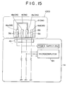
- the connector 45 is connected to a microcomputer 64 by a flexible printed wiring board 63.
- the connecting portions 58a of the detecting contacts 56 are connected to the conductors 65 of the flexible printed wiring board 63, respectively.
- the upper ends of the contact portions 59a of the detecting contacts 56 of the connector 45 come into contact with the terminals 18 (35) of the tape cassette 1 (20).
- the upper arms 59 of the detecting contacts 56 are flexed downward, the extremities 59b of the upper arms 59 are separated from the lower surface of the overhang 49 of the casing 46, and the upper ends of the upper arms 53 move slightly forward and come into contact with the contacts 18 (35).
- the upper ends of the contact portions 59a are in resilient contact with the contacts 18 (35).
- a supply voltage is applied, for example, to the contact 18a (35a), and a three-bit signal produced by the contacts 18b, 18c and 18d (35b, 35c and 35d) is sent to the microcomputer 64.
- the three-bit signal is [0 1 0].
- eight three-bit signals from [0 0 0] to [1 1 1] can be produced by selectively connecting the contacts 18b, 18c and/or 18d (35b, 35c and/or 35d) and the contact 18a (35a).
- each of the contacts 18b (35b), 18c (35c) and 18d (35d) is connected or not connected to the contact 18a (35a) to make the same to represent "0" or "1".
- the second embodiment employs a printed wiring board 74 provided with contacts 73a, 73b, 73c and 73d which are kept open, short-circuited or connected through a resistor to a ground to represent three states by each of the contacts 73a, 73b, 73c and 73d.
- the contact 73a is connected to the contact 73c by a conductor 75A and through a conductor 75B, a chip resistor 76 and a conductor 75C to the contact 73d.
- the contacts 73a and 73c are short-circuited, the chip resistor 76 is interposed between the contacts 73a and 73d, and the contacts 73a and 73b separated from each other.
- the printed wiring board 74 similarly to the printed wiring boards 17 and 34, is fixedly fitted in the recess 15 (32) of the case 2 (21).
- the contacts 73a, 73b, 73c and 73d of the printed wiring board 74 are brought into contact respectively with the detecting contacts 78a, 78b, 78c and 78d of a connector 77 included in the VTR 71 when the tape cassette 70 is inserted in the VTR 71.
- the contact 73d is connected through the detecting contact 78d to the input terminal of a voltage comparator 79A, and through a resistor 80d to the output terminal of a power supply 81.
- the contact 73c is connected through the detecting contact 78c to the input terminal of a voltage comparator 79B and through a resistor 80c to the output terminal of the power supply 81.
- the contact 73b is connected through the detecting contact 78b to the input terminal of a voltage comparator 79C, and through a resistor 80b to the output terminal of the power supply 81.
- the contact 73a is connected through the detecting contact 78a to a ground.
- the voltage comparators 79A, 79B and 79C detect the respective potentials of the detecting contacts 78b, 78c and 78d, respectively, and determine detection ranges in which the potentials of the corresponding detecting contacts 78b, 78c and 78d fall, and give either of two binary signals D1 and D2 representing the detection ranges through a data conversion circuit 82 to a microcomputer 83.
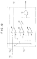
- the voltage comparators 79A, 79B and 79C are identical in configuration and hence only the voltage comparator 79A will be described.
- the voltage comparator 79A comprises three comparators 84, 85 and 86, a resistor 87, a NOT gate 88 and an AND gate 89.
- the potential of the directing contact 78d is applied to the positive input terminals of the comparators 84 and 85.
- a reference voltage for example, about 3 V, obtained by dividing the supply voltage, for example, 5 V, of the power supply 81 by the resistor 87 is applied to the negative input terminals of the comparators 84 and 85.
- the output signal D1 of the comparator 84 appears at a terminal, the output signal of the comparator 85 is applied to the input terminal of the NOT gate 88, and the output signal of the NOT gate 88 is given to the AND gate 89.
- the potential of the detecting contact 80d is applied to the positive input terminal of the comparator 86, a reference voltage lower than the reference voltage for the comparators 84 and 85, for example, about 2 V, obtained by dividing the supply voltage by the resistor 87 is applied to the negative input terminal of the comparator 86, and the output signal of the comparator 86 is applied to the AND gate 89.
- the AND gate 89 receives the signal provided by the comparator 85 through the NOT gate 88 and the output signal of the comparator 86, processes the input signals by an AND operation, and provides a signal D2 obtained by the AND operation.
- the output signals of the comparators 84 and 85 goes HIGH and, consequently, the signal D1 goes HIGH.
- the output signal of the comparator 85 is HIGH, the output of the NOT gate 88, i.e., the complement of the input signal, applied to the AND gate 89 goes LOW and, consequently, the signal D2 goes LOW.
- the output signals of the comparators 84 and 85 goes LOW and hence the signal D1 goes LOW. Since the output signal of the NOT gate 88, i.e., the complement of the output signal LOW of the comparator 85, is HIGH and the output signal of the comparator 86 is HIGH, the signal D2 goes HIGH.
- the potential of the detecting contact 78d is 2.5 V and hence the output signals D1 and D2 of the voltage comparator 79A are LOW and HIGH, respectively.
- both the output signals D1 and D2 of the voltage comparator 79B are LOW. Since the potential of the detecting contact 78b is 5 V, the output signals D1 and D2 of the voltage comparator 79C are HIGH and LOW, respectively.
- the output signals D1 and D2 of the voltage comparators 79A, 79B and 79C are applied to the input terminals I1 to I6 of the data conversion circuit 82, and then the data conversion circuit 82 converts these input signals representing parallel data into corresponding serial data and gives the serial data to the microcomputer 83.
- the microcomputer 83 processes the serial data to determine the type of the tape cassette, the length and type of the tape and the like on the basis of the serial data.
- N to M power pieces of information can be indicated by using M contacts and a detecting circuit capable of detecting N kinds of state of each of the M contacts.
- the printed wiring board provided with the contacts is disposed on the bottom wall of the case of the tape cassette in the foregoing embodiments, the printed wiring board may be placed on the rear wall, side wall or top wall of the case of the tape cassette.
Priority Applications (1)
| Application Number | Priority Date | Filing Date | Title |
|---|---|---|---|
| EP97108524A EP0791920A3 (de) | 1992-06-01 | 1993-05-27 | Aufzeichnungskassette und Aufnahme-/Wiedergabegerät |
Applications Claiming Priority (6)
| Application Number | Priority Date | Filing Date | Title |
|---|---|---|---|
| JP16341492A JP3334163B2 (ja) | 1992-06-01 | 1992-06-01 | 記録媒体カセット及び記録再生装置 |
| JP163414/92 | 1992-06-01 | ||
| JP16544392 | 1992-06-02 | ||
| JP165443/92 | 1992-06-02 | ||
| JP209470/92 | 1992-07-15 | ||
| JP4209470A JPH0652650A (ja) | 1992-06-02 | 1992-07-15 | 記録媒体カセットと記録再生装置 |
Related Child Applications (1)
| Application Number | Title | Priority Date | Filing Date |
|---|---|---|---|
| EP97108524A Division EP0791920A3 (de) | 1992-06-01 | 1993-05-27 | Aufzeichnungskassette und Aufnahme-/Wiedergabegerät |
Publications (2)
| Publication Number | Publication Date |
|---|---|
| EP0572925A1 true EP0572925A1 (de) | 1993-12-08 |
| EP0572925B1 EP0572925B1 (de) | 1999-03-17 |
Family
ID=27322159
Family Applications (2)
| Application Number | Title | Priority Date | Filing Date |
|---|---|---|---|
| EP93108605A Expired - Lifetime EP0572925B1 (de) | 1992-06-01 | 1993-05-27 | Aufzeichnungskassette und Aufnahme-/Wiedergabegerät |
| EP97108524A Ceased EP0791920A3 (de) | 1992-06-01 | 1993-05-27 | Aufzeichnungskassette und Aufnahme-/Wiedergabegerät |
Family Applications After (1)
| Application Number | Title | Priority Date | Filing Date |
|---|---|---|---|
| EP97108524A Ceased EP0791920A3 (de) | 1992-06-01 | 1993-05-27 | Aufzeichnungskassette und Aufnahme-/Wiedergabegerät |
Country Status (6)
| Country | Link |
|---|---|
| US (2) | US5390870A (de) |
| EP (2) | EP0572925B1 (de) |
| AU (1) | AU3991793A (de) |
| CA (1) | CA2097410C (de) |
| DE (1) | DE69323927T2 (de) |
| TW (2) | TW306665U (de) |
Cited By (8)
| Publication number | Priority date | Publication date | Assignee | Title |
|---|---|---|---|---|
| EP0599718A2 (de) * | 1992-11-25 | 1994-06-01 | Sony Corporation | Bandkassetten und Aufzeichnungs- und/oder Wiedergabegerät |
| EP0632452A2 (de) * | 1993-06-15 | 1995-01-04 | Hitachi Maxell Ltd. | Bandkassette für Zweiwegesystem |
| EP0646914A2 (de) * | 1993-09-30 | 1995-04-05 | Sony Corporation | Kassetten mit Speichern |
| EP0720163A2 (de) * | 1994-12-27 | 1996-07-03 | Sony Corporation | Magnetaufzeichnungs- und Wiedergabegerät und Reinigungskassette dafür |
| WO1999042997A1 (en) * | 1998-02-20 | 1999-08-26 | Fuji Photo Film Co., Ltd. | An id board of a magnetic tape cassette |
| US6097558A (en) * | 1994-03-31 | 2000-08-01 | Sony Corporation | Digital audio signal transmission apparatus with data blocks of varying sizes |
| EP1148499A1 (de) * | 1998-11-30 | 2001-10-24 | Fuji Photo Film Co., Ltd. | Magnetbandkassette |
| US6735048B2 (en) | 2000-12-25 | 2004-05-11 | Sony Corporation | Tape cassette |
Families Citing this family (14)
| Publication number | Priority date | Publication date | Assignee | Title |
|---|---|---|---|---|
| EP0874367A3 (de) * | 1992-11-13 | 2000-04-05 | Sony Corporation | Kassette für Aufzeichnungsmedium |
| JP3413903B2 (ja) * | 1993-09-14 | 2003-06-09 | ソニー株式会社 | 記録媒体カセット |
| JP3166473B2 (ja) * | 1994-03-15 | 2001-05-14 | ソニー株式会社 | 記録再生装置 |
| WO1996008013A1 (fr) * | 1994-09-06 | 1996-03-14 | Sony Corporation | Support d'enregistrement |
| JP3475587B2 (ja) * | 1995-07-19 | 2003-12-08 | 松下電器産業株式会社 | パッケージ中継端子及び記録再生機器 |
| US6038368A (en) * | 1996-02-05 | 2000-03-14 | Sony Corporation | System for acquiring, reviewing, and editing sports video segments |
| KR100200597B1 (ko) * | 1996-07-15 | 1999-06-15 | 윤종용 | 테이프 레코더의 오디오/콘트롤헤드 접속장치 |
| AU2227799A (en) * | 1998-01-26 | 1999-08-09 | Smartdisk Corporation | Adapter |
| US6088635A (en) * | 1998-09-28 | 2000-07-11 | Roadtrac, Llc | Railroad vehicle accident video recorder |
| JP3482886B2 (ja) * | 1998-09-29 | 2004-01-06 | 松下電器産業株式会社 | 磁気記録再生装置 |
| KR20010103628A (ko) * | 2000-05-08 | 2001-11-23 | 이데이 노부유끼 | 테이프 카세트와 정보저장장치 |
| DE10239784B4 (de) * | 2002-08-29 | 2004-12-30 | Tecpharma Licensing Ag | Injektions-, Infusions- oder Inhalationsvorrichtung mit Dosisanzeigevorrichtung |
| US7377460B2 (en) * | 2003-10-16 | 2008-05-27 | Hitachi Maxell Ltd. | Tape cartridge of compatible type |
| JP2006053967A (ja) * | 2004-08-10 | 2006-02-23 | Hitachi Maxell Ltd | 磁気テープカートリッジ |
Citations (9)
| Publication number | Priority date | Publication date | Assignee | Title |
|---|---|---|---|---|
| GB1315142A (en) * | 1969-04-30 | 1973-04-26 | Canon Kk | Cartridge containing a magnetic recording medium |
| US4338644A (en) * | 1978-10-27 | 1982-07-06 | Staar S. A. | Magnetic tape cassettes provided with memory circuits for storing information |
| WO1984003791A1 (en) * | 1983-03-16 | 1984-09-27 | Alfredo Leone | Video cassette play counting, storing and reading system |
| EP0265167A2 (de) * | 1986-10-15 | 1988-04-27 | Pioneer Electronic Corporation | Plattenwiedergabegerät mit Plattenmagazin |
| US4743984A (en) * | 1985-09-25 | 1988-05-10 | Ampex Corporation | Scheme for encoding a magnetic tape cassette |
| GB2208029A (en) * | 1987-08-13 | 1989-02-15 | Nintendo Co Ltd | Data recording device with I.D. symbol |
| EP0373718A2 (de) * | 1988-12-14 | 1990-06-20 | Koninklijke Philips Electronics N.V. | Aufzeichnungs- und/oder Wiedergabesystem und Kassette für ein solches System |
| WO1991002355A1 (en) * | 1989-08-07 | 1991-02-21 | Bang & Olufsen A/S | A recording and play-back system, primarily a video system, using tape cassettes |
| EP0533002A1 (de) * | 1991-09-19 | 1993-03-24 | Deutsche Thomson-Brandt Gmbh | Kassette für einen Recorder |
Family Cites Families (16)
| Publication number | Priority date | Publication date | Assignee | Title |
|---|---|---|---|---|
| US3601558A (en) * | 1967-11-20 | 1971-08-24 | Matsushita Electric Ind Co Ltd | Cartridge-type magnetic tape recording and reproducing apparatus with means to indicate the coercivity of the tape |
| US3711654A (en) * | 1969-04-30 | 1973-01-16 | Canon Kk | Magnetic recording and reproducing device for use with an endless recording medium with means for indicating a recordable state with-in one cycle of the endless recording medium |
| JPS5540624Y2 (de) * | 1975-04-17 | 1980-09-22 | ||
| JPS5552564A (en) * | 1978-10-13 | 1980-04-17 | Sony Corp | Check unit for suitability of stuck label of tape cassette |
| BE885102R (fr) * | 1978-10-27 | 1980-12-31 | Staar Sa | Dispositif de memorisation de la position instantanee d'une bande magnetique contenue dans une cassette |
| FR2461299B1 (fr) * | 1979-07-09 | 1986-09-05 | Telediffusion Fse | Memoire bloc-note pour cassettes d'enregistrement de bandes magnetiques |
| JPS5952067B2 (ja) * | 1980-12-15 | 1984-12-18 | 純夫 内藤 | 溝付化粧板 |
| JPS57100666A (en) * | 1980-12-15 | 1982-06-22 | Mitsubishi Electric Corp | Magnetic recorder and reproducer |
| JPS6194287A (ja) * | 1984-10-16 | 1986-05-13 | Sony Corp | 磁気記録カセツト |
| US4839875A (en) * | 1986-05-19 | 1989-06-13 | Anritsu Corporation | Technique for automatic tracking of cassette rentals and managing of information related thereto |
| JPS6391884U (de) * | 1986-12-04 | 1988-06-14 | ||
| US4897750A (en) * | 1988-05-09 | 1990-01-30 | Minnesota Mining And Manufacturing Company | Encodable insert for a recording cassette |
| JPH0720781Y2 (ja) * | 1988-07-06 | 1995-05-15 | ティーディーケイ株式会社 | カセット型記録体 |
| US5239437A (en) * | 1991-08-12 | 1993-08-24 | Minnesota Mining And Manufacturing Company | Self identifying universal data storage element |
| DE4214446C2 (de) * | 1992-05-06 | 2001-03-29 | Thomson Brandt Gmbh | Kassette mit einem Aufzeichnungsträger und mit elektrischen Kontaktflächen zum Auslesen von an der Kassette gespeicherten, kassettentypischen Daten, sowie diesbezüglicher Recorder |
| JP3287423B2 (ja) * | 1992-11-25 | 2002-06-04 | ソニー株式会社 | テープカセット及び記録再生装置 |
-
1993
- 1993-05-27 US US08/067,811 patent/US5390870A/en not_active Ceased
- 1993-05-27 EP EP93108605A patent/EP0572925B1/de not_active Expired - Lifetime
- 1993-05-27 EP EP97108524A patent/EP0791920A3/de not_active Ceased
- 1993-05-27 DE DE69323927T patent/DE69323927T2/de not_active Expired - Fee Related
- 1993-05-31 AU AU39917/93A patent/AU3991793A/en not_active Abandoned
- 1993-05-31 CA CA002097410A patent/CA2097410C/en not_active Expired - Fee Related
- 1993-06-07 TW TW084208337U patent/TW306665U/zh unknown
- 1993-06-07 TW TW084210356U patent/TW295294U/zh unknown
-
1996
- 1996-03-18 US US08/618,423 patent/USRE35950E/en not_active Expired - Lifetime
Patent Citations (9)
| Publication number | Priority date | Publication date | Assignee | Title |
|---|---|---|---|---|
| GB1315142A (en) * | 1969-04-30 | 1973-04-26 | Canon Kk | Cartridge containing a magnetic recording medium |
| US4338644A (en) * | 1978-10-27 | 1982-07-06 | Staar S. A. | Magnetic tape cassettes provided with memory circuits for storing information |
| WO1984003791A1 (en) * | 1983-03-16 | 1984-09-27 | Alfredo Leone | Video cassette play counting, storing and reading system |
| US4743984A (en) * | 1985-09-25 | 1988-05-10 | Ampex Corporation | Scheme for encoding a magnetic tape cassette |
| EP0265167A2 (de) * | 1986-10-15 | 1988-04-27 | Pioneer Electronic Corporation | Plattenwiedergabegerät mit Plattenmagazin |
| GB2208029A (en) * | 1987-08-13 | 1989-02-15 | Nintendo Co Ltd | Data recording device with I.D. symbol |
| EP0373718A2 (de) * | 1988-12-14 | 1990-06-20 | Koninklijke Philips Electronics N.V. | Aufzeichnungs- und/oder Wiedergabesystem und Kassette für ein solches System |
| WO1991002355A1 (en) * | 1989-08-07 | 1991-02-21 | Bang & Olufsen A/S | A recording and play-back system, primarily a video system, using tape cassettes |
| EP0533002A1 (de) * | 1991-09-19 | 1993-03-24 | Deutsche Thomson-Brandt Gmbh | Kassette für einen Recorder |
Non-Patent Citations (1)
| Title |
|---|
| PATENT ABSTRACTS OF JAPAN vol. 10, no. 271 (P-497)(2327) 16 September 1986 & JP-A-61 94 287 ( SONY ) 13 May 1986 * |
Cited By (18)
| Publication number | Priority date | Publication date | Assignee | Title |
|---|---|---|---|---|
| EP0599718A2 (de) * | 1992-11-25 | 1994-06-01 | Sony Corporation | Bandkassetten und Aufzeichnungs- und/oder Wiedergabegerät |
| EP0599718A3 (de) * | 1992-11-25 | 1995-02-15 | Sony Corp | Bandkassetten und Aufzeichnungs- und/oder Wiedergabegerät. |
| US5506736A (en) * | 1992-11-25 | 1996-04-09 | Sony Corporation | Memory arrangement for tape cassettes used in recording and/or reproduction |
| EP0632452A2 (de) * | 1993-06-15 | 1995-01-04 | Hitachi Maxell Ltd. | Bandkassette für Zweiwegesystem |
| EP0632452A3 (en) * | 1993-06-15 | 1995-02-01 | Hitachi Maxell | Tape cartridge of two-way system. |
| EP0646914A2 (de) * | 1993-09-30 | 1995-04-05 | Sony Corporation | Kassetten mit Speichern |
| EP0880141A3 (de) * | 1993-09-30 | 2002-12-04 | Sony Corporation | Kassetten mit Speichern |
| EP0646914A3 (de) * | 1993-09-30 | 1996-11-27 | Sony Corp | Kassetten mit Speichern. |
| US6101070A (en) * | 1993-09-30 | 2000-08-08 | Sony Corporation | Method and apparatus for determining information and a cassette for use therewith |
| EP0880141A2 (de) * | 1993-09-30 | 1998-11-25 | Sony Corporation | Kassetten mit Speichern |
| US5907444A (en) * | 1993-09-30 | 1999-05-25 | Sony Corporation | Apparatus for recording and/or reproducing information for use with a cassette having a memory and method thereof |
| US6097558A (en) * | 1994-03-31 | 2000-08-01 | Sony Corporation | Digital audio signal transmission apparatus with data blocks of varying sizes |
| EP0720163A3 (de) * | 1994-12-27 | 1997-06-11 | Sony Corp | Magnetaufzeichnungs- und Wiedergabegerät und Reinigungskassette dafür |
| EP0720163A2 (de) * | 1994-12-27 | 1996-07-03 | Sony Corporation | Magnetaufzeichnungs- und Wiedergabegerät und Reinigungskassette dafür |
| WO1999042997A1 (en) * | 1998-02-20 | 1999-08-26 | Fuji Photo Film Co., Ltd. | An id board of a magnetic tape cassette |
| EP1148499A1 (de) * | 1998-11-30 | 2001-10-24 | Fuji Photo Film Co., Ltd. | Magnetbandkassette |
| EP1148499A4 (de) * | 1998-11-30 | 2007-08-01 | Fujifilm Corp | Magnetbandkassette |
| US6735048B2 (en) | 2000-12-25 | 2004-05-11 | Sony Corporation | Tape cassette |
Also Published As
| Publication number | Publication date |
|---|---|
| CA2097410A1 (en) | 1993-12-02 |
| DE69323927D1 (de) | 1999-04-22 |
| EP0791920A3 (de) | 1997-11-19 |
| USRE35950E (en) | 1998-11-10 |
| EP0572925B1 (de) | 1999-03-17 |
| CA2097410C (en) | 2002-02-19 |
| US5390870A (en) | 1995-02-21 |
| TW295294U (en) | 1997-01-01 |
| AU3991793A (en) | 1993-12-02 |
| EP0791920A2 (de) | 1997-08-27 |
| DE69323927T2 (de) | 1999-08-05 |
| TW306665U (en) | 1997-05-21 |
Similar Documents
| Publication | Publication Date | Title |
|---|---|---|
| US5390870A (en) | Recording medium cassette and a recording/reproducing apparatus | |
| EP0599718B1 (de) | Bandkassetten und Aufzeichnungs- und/oder Wiedergabegerät | |
| US6456491B1 (en) | Modular floppy disk drive for internal and external use | |
| US5434721A (en) | Recording/reproducing apparatus for recording/reproducing information to and/or from a plurality of types of recording medium cassettes | |
| US20030119350A1 (en) | Card ejection mechanism for electronic card connector | |
| US5583745A (en) | Data recording and reproducing device comprising a memory unit used for a memory card | |
| US4894739A (en) | Disc recording and/or reproducing apparatus | |
| EP0795868B1 (de) | Aufzeichnungsträgerkassette, Anzeigegerät und Aufzeichnungs-/Wiedergabegerät | |
| EP0597726A2 (de) | Aufzeichnungs- und Wiedergabegerät und Duplizierverfahren für Aufzeichnungsmediumkassette | |
| JP3334256B2 (ja) | テープカセット | |
| KR100263681B1 (ko) | 기록매체 카세트 및 기록/재생장치 | |
| JP3454266B2 (ja) | 記録再生装置 | |
| KR100253040B1 (ko) | 기록 및 재생 장치 | |
| USRE35713E (en) | Disc recording and/or reproducing apparatus | |
| JPH0652650A (ja) | 記録媒体カセットと記録再生装置 | |
| JP2001229352A (ja) | メモリーカードカートリッジ及びその装着装置並びにメモリーカード装着システム | |
| JP3306852B2 (ja) | 記録媒体カセットの記録再生装置 | |
| US4754429A (en) | Cassette type magnetic bubble memory | |
| JPH06259928A (ja) | 記録媒体カセット | |
| JPH08282776A (ja) | カセットケース及びそのカセットラック装置 | |
| KR20020057551A (ko) | 컴팩트플래쉬어댑터 및 휴대용 데이터처리장치 | |
| JPH0644741A (ja) | 記録媒体カセット | |
| JP2003045150A (ja) | 磁気テープカセット | |
| JPH08306166A (ja) | 記録再生用カセット | |
| JP2003045152A (ja) | 磁気テープカセット |
Legal Events
| Date | Code | Title | Description |
|---|---|---|---|
| PUAI | Public reference made under article 153(3) epc to a published international application that has entered the european phase |
Free format text: ORIGINAL CODE: 0009012 |
|
| AK | Designated contracting states |
Kind code of ref document: A1 Designated state(s): DE FR GB IT NL |
|
| 17P | Request for examination filed |
Effective date: 19940506 |
|
| 17Q | First examination report despatched |
Effective date: 19961108 |
|
| GRAG | Despatch of communication of intention to grant |
Free format text: ORIGINAL CODE: EPIDOS AGRA |
|
| GRAG | Despatch of communication of intention to grant |
Free format text: ORIGINAL CODE: EPIDOS AGRA |
|
| GRAH | Despatch of communication of intention to grant a patent |
Free format text: ORIGINAL CODE: EPIDOS IGRA |
|
| GRAH | Despatch of communication of intention to grant a patent |
Free format text: ORIGINAL CODE: EPIDOS IGRA |
|
| GRAA | (expected) grant |
Free format text: ORIGINAL CODE: 0009210 |
|
| AK | Designated contracting states |
Kind code of ref document: B1 Designated state(s): DE FR GB IT NL |
|
| DX | Miscellaneous (deleted) | ||
| REF | Corresponds to: |
Ref document number: 69323927 Country of ref document: DE Date of ref document: 19990422 |
|
| ITF | It: translation for a ep patent filed |
Owner name: SOCIETA' ITALIANA BREVETTI S.P.A. |
|
| ET | Fr: translation filed | ||
| PLBE | No opposition filed within time limit |
Free format text: ORIGINAL CODE: 0009261 |
|
| STAA | Information on the status of an ep patent application or granted ep patent |
Free format text: STATUS: NO OPPOSITION FILED WITHIN TIME LIMIT |
|
| 26N | No opposition filed | ||
| REG | Reference to a national code |
Ref country code: GB Ref legal event code: IF02 |
|
| PGFP | Annual fee paid to national office [announced via postgrant information from national office to epo] |
Ref country code: DE Payment date: 20080605 Year of fee payment: 16 |
|
| PGFP | Annual fee paid to national office [announced via postgrant information from national office to epo] |
Ref country code: IT Payment date: 20080528 Year of fee payment: 16 |
|
| PGFP | Annual fee paid to national office [announced via postgrant information from national office to epo] |
Ref country code: GB Payment date: 20080528 Year of fee payment: 16 |
|
| PGFP | Annual fee paid to national office [announced via postgrant information from national office to epo] |
Ref country code: NL Payment date: 20090504 Year of fee payment: 17 |
|
| GBPC | Gb: european patent ceased through non-payment of renewal fee |
Effective date: 20090527 |
|
| REG | Reference to a national code |
Ref country code: FR Ref legal event code: ST Effective date: 20100129 |
|
| PG25 | Lapsed in a contracting state [announced via postgrant information from national office to epo] |
Ref country code: FR Free format text: LAPSE BECAUSE OF NON-PAYMENT OF DUE FEES Effective date: 20090602 |
|
| PGFP | Annual fee paid to national office [announced via postgrant information from national office to epo] |
Ref country code: FR Payment date: 20080514 Year of fee payment: 16 |
|
| PG25 | Lapsed in a contracting state [announced via postgrant information from national office to epo] |
Ref country code: GB Free format text: LAPSE BECAUSE OF NON-PAYMENT OF DUE FEES Effective date: 20090527 |
|
| PG25 | Lapsed in a contracting state [announced via postgrant information from national office to epo] |
Ref country code: DE Free format text: LAPSE BECAUSE OF NON-PAYMENT OF DUE FEES Effective date: 20091201 |
|
| REG | Reference to a national code |
Ref country code: NL Ref legal event code: V1 Effective date: 20101201 |
|
| PG25 | Lapsed in a contracting state [announced via postgrant information from national office to epo] |
Ref country code: NL Free format text: LAPSE BECAUSE OF NON-PAYMENT OF DUE FEES Effective date: 20101201 Ref country code: IT Free format text: LAPSE BECAUSE OF NON-PAYMENT OF DUE FEES Effective date: 20090527 |