EP0572329B1 - Vorrichtung und Verfahren zum gleichzeitigen Strangpressen von dünnen Schichten - Google Patents
Vorrichtung und Verfahren zum gleichzeitigen Strangpressen von dünnen Schichten Download PDFInfo
- Publication number
- EP0572329B1 EP0572329B1 EP93420197A EP93420197A EP0572329B1 EP 0572329 B1 EP0572329 B1 EP 0572329B1 EP 93420197 A EP93420197 A EP 93420197A EP 93420197 A EP93420197 A EP 93420197A EP 0572329 B1 EP0572329 B1 EP 0572329B1
- Authority
- EP
- European Patent Office
- Prior art keywords
- slot
- land
- die
- downstream
- upstream
- Prior art date
- Legal status (The legal status is an assumption and is not a legal conclusion. Google has not performed a legal analysis and makes no representation as to the accuracy of the status listed.)
- Expired - Lifetime
Links
- 238000000034 method Methods 0.000 title claims description 17
- 238000005266 casting Methods 0.000 claims description 48
- 239000000758 substrate Substances 0.000 claims description 34
- 239000000203 mixture Substances 0.000 claims description 30
- 238000011144 upstream manufacturing Methods 0.000 claims description 28
- 238000001125 extrusion Methods 0.000 claims description 18
- 239000007788 liquid Substances 0.000 claims description 13
- 229920000642 polymer Polymers 0.000 claims description 10
- 239000002904 solvent Substances 0.000 claims description 8
- 230000001154 acute effect Effects 0.000 claims description 4
- 238000004519 manufacturing process Methods 0.000 claims description 3
- 239000010410 layer Substances 0.000 description 48
- 239000002346 layers by function Substances 0.000 description 20
- YMWUJEATGCHHMB-UHFFFAOYSA-N Dichloromethane Chemical compound ClCCl YMWUJEATGCHHMB-UHFFFAOYSA-N 0.000 description 12
- OKKJLVBELUTLKV-UHFFFAOYSA-N Methanol Chemical compound OC OKKJLVBELUTLKV-UHFFFAOYSA-N 0.000 description 9
- 230000000052 comparative effect Effects 0.000 description 6
- 230000003287 optical effect Effects 0.000 description 6
- 238000009826 distribution Methods 0.000 description 5
- 229920002284 Cellulose triacetate Polymers 0.000 description 4
- UQSXHKLRYXJYBZ-UHFFFAOYSA-N Iron oxide Chemical compound [Fe]=O UQSXHKLRYXJYBZ-UHFFFAOYSA-N 0.000 description 4
- NNLVGZFZQQXQNW-ADJNRHBOSA-N [(2r,3r,4s,5r,6s)-4,5-diacetyloxy-3-[(2s,3r,4s,5r,6r)-3,4,5-triacetyloxy-6-(acetyloxymethyl)oxan-2-yl]oxy-6-[(2r,3r,4s,5r,6s)-4,5,6-triacetyloxy-2-(acetyloxymethyl)oxan-3-yl]oxyoxan-2-yl]methyl acetate Chemical compound O([C@@H]1O[C@@H]([C@H]([C@H](OC(C)=O)[C@H]1OC(C)=O)O[C@H]1[C@@H]([C@@H](OC(C)=O)[C@H](OC(C)=O)[C@@H](COC(C)=O)O1)OC(C)=O)COC(=O)C)[C@@H]1[C@@H](COC(C)=O)O[C@@H](OC(C)=O)[C@H](OC(C)=O)[C@H]1OC(C)=O NNLVGZFZQQXQNW-ADJNRHBOSA-N 0.000 description 4
- 239000006185 dispersion Substances 0.000 description 4
- 239000011248 coating agent Substances 0.000 description 3
- 238000000576 coating method Methods 0.000 description 3
- -1 poly(ethylene terephthalate) Polymers 0.000 description 3
- 239000007787 solid Substances 0.000 description 3
- LRHPLDYGYMQRHN-UHFFFAOYSA-N N-Butanol Chemical compound CCCCO LRHPLDYGYMQRHN-UHFFFAOYSA-N 0.000 description 2
- 238000005452 bending Methods 0.000 description 2
- 230000015572 biosynthetic process Effects 0.000 description 2
- 229920002678 cellulose Polymers 0.000 description 2
- 230000009977 dual effect Effects 0.000 description 2
- 239000000975 dye Substances 0.000 description 2
- 239000002184 metal Substances 0.000 description 2
- 229910052751 metal Inorganic materials 0.000 description 2
- XDTMQSROBMDMFD-UHFFFAOYSA-N Cyclohexane Chemical compound C1CCCCC1 XDTMQSROBMDMFD-UHFFFAOYSA-N 0.000 description 1
- 239000000872 buffer Substances 0.000 description 1
- 239000003795 chemical substances by application Substances 0.000 description 1
- 230000008020 evaporation Effects 0.000 description 1
- 238000001704 evaporation Methods 0.000 description 1
- 239000006249 magnetic particle Substances 0.000 description 1
- 238000012986 modification Methods 0.000 description 1
- 230000004048 modification Effects 0.000 description 1
- 239000002245 particle Substances 0.000 description 1
- 230000000704 physical effect Effects 0.000 description 1
- 239000000049 pigment Substances 0.000 description 1
- 239000004033 plastic Substances 0.000 description 1
- 229920000139 polyethylene terephthalate Polymers 0.000 description 1
- 239000005020 polyethylene terephthalate Substances 0.000 description 1
- 229910001220 stainless steel Inorganic materials 0.000 description 1
- 239000010935 stainless steel Substances 0.000 description 1
Images
Classifications
-
- B—PERFORMING OPERATIONS; TRANSPORTING
- B29—WORKING OF PLASTICS; WORKING OF SUBSTANCES IN A PLASTIC STATE IN GENERAL
- B29C—SHAPING OR JOINING OF PLASTICS; SHAPING OF MATERIAL IN A PLASTIC STATE, NOT OTHERWISE PROVIDED FOR; AFTER-TREATMENT OF THE SHAPED PRODUCTS, e.g. REPAIRING
- B29C48/00—Extrusion moulding, i.e. expressing the moulding material through a die or nozzle which imparts the desired form; Apparatus therefor
- B29C48/25—Component parts, details or accessories; Auxiliary operations
- B29C48/30—Extrusion nozzles or dies
- B29C48/305—Extrusion nozzles or dies having a wide opening, e.g. for forming sheets
- B29C48/307—Extrusion nozzles or dies having a wide opening, e.g. for forming sheets specially adapted for bringing together components, e.g. melts within the die
-
- B—PERFORMING OPERATIONS; TRANSPORTING
- B29—WORKING OF PLASTICS; WORKING OF SUBSTANCES IN A PLASTIC STATE IN GENERAL
- B29C—SHAPING OR JOINING OF PLASTICS; SHAPING OF MATERIAL IN A PLASTIC STATE, NOT OTHERWISE PROVIDED FOR; AFTER-TREATMENT OF THE SHAPED PRODUCTS, e.g. REPAIRING
- B29C48/00—Extrusion moulding, i.e. expressing the moulding material through a die or nozzle which imparts the desired form; Apparatus therefor
- B29C48/03—Extrusion moulding, i.e. expressing the moulding material through a die or nozzle which imparts the desired form; Apparatus therefor characterised by the shape of the extruded material at extrusion
- B29C48/07—Flat, e.g. panels
- B29C48/08—Flat, e.g. panels flexible, e.g. films
-
- B—PERFORMING OPERATIONS; TRANSPORTING
- B29—WORKING OF PLASTICS; WORKING OF SUBSTANCES IN A PLASTIC STATE IN GENERAL
- B29C—SHAPING OR JOINING OF PLASTICS; SHAPING OF MATERIAL IN A PLASTIC STATE, NOT OTHERWISE PROVIDED FOR; AFTER-TREATMENT OF THE SHAPED PRODUCTS, e.g. REPAIRING
- B29C48/00—Extrusion moulding, i.e. expressing the moulding material through a die or nozzle which imparts the desired form; Apparatus therefor
- B29C48/16—Articles comprising two or more components, e.g. co-extruded layers
- B29C48/18—Articles comprising two or more components, e.g. co-extruded layers the components being layers
- B29C48/21—Articles comprising two or more components, e.g. co-extruded layers the components being layers the layers being joined at their surfaces
-
- B—PERFORMING OPERATIONS; TRANSPORTING
- B29—WORKING OF PLASTICS; WORKING OF SUBSTANCES IN A PLASTIC STATE IN GENERAL
- B29L—INDEXING SCHEME ASSOCIATED WITH SUBCLASS B29C, RELATING TO PARTICULAR ARTICLES
- B29L2007/00—Flat articles, e.g. films or sheets
- B29L2007/008—Wide strips, e.g. films, webs
-
- B—PERFORMING OPERATIONS; TRANSPORTING
- B29—WORKING OF PLASTICS; WORKING OF SUBSTANCES IN A PLASTIC STATE IN GENERAL
- B29L—INDEXING SCHEME ASSOCIATED WITH SUBCLASS B29C, RELATING TO PARTICULAR ARTICLES
- B29L2009/00—Layered products
Definitions
- This invention relates to an apparatus and method for casting polymeric films having two or more layers and, more particularly, to such a method and apparatus for simultaneous casting of the layers.
- the prior art discloses apparatus for the simultaneous deposit of two or more layers of solutions or dispersions.
- the patent to Bartlett et al, U.S. 2,932,855 discloses a multislotted die for simultaneously casting a plurality of layers of polymer compositions on a moving drum.
- Prior art devices are not satisfactory for casting two or more layers with a high degree of uniformity when the viscosities of the casting solutions or dispersions (also known as dopes in non-aqueous systems) or the thicknesses of the layers differ greatly.
- Films of this kind include, photographic films that have a magnetic recording layer as disclosed, for example, in the patent to Krall, U.S. 3,782,947. They have a thin magnetic layer and a much thicker cellulosic support layer. Also, they are coated from dopes which differ greatly in viscosity and cannot be cocast precisely with conventional casting dies.
- the present invention provides a novel apparatus and method by means of which plural layer films can be cocast with high precision despite great differences in the thicknesses of the layers and the viscosities of the dopes.
- dope viscosity ratios can be as high as 300,000 to 1 and thickness ratios can range from 5000:1 to 1:1.
- the apparatus of the invention comprises a novel cocasting die for the manufacture of polymeric films having two or more layers and includes the combination of the novel die with a casting substrate which is adapted to move continuously in a downstream direction.
- the cocasting die is positioned adjacent the substrate for extruding simultaneously two or more casting compositions in continuous layers onto the moving substrate.
- the die has an upstream side and a downstream side and comprises an assembly of die elements which form a block containing an upstream extrusion slot on the upstream side of the die and a downstream extrusion slot on the downstream side of the die.
- the die further comprises a plurality of distribution cavities for receiving casting compositions and feeding same at a constant rate to respective extrusion slots.
- Each of the slots has narrowly spaced-apart parallel walls extending from a cavity to lips which form an elongated slot exit, the slot exits being mutually parallel.
- the die is so positioned that the slot exits are spaced above and close to the substrate, with the long dimensions of the slot exits being perpendicular to the direction of movement of the substrate.
- the upstream slot exit has an outer lip comprising a first planar rectangular land which is coextensive in length with the slot exit, said planar rectangular land forming an acute angle with the planar upstream wall of the slot and extending in the widthwise, upstream direction to a pinning line formed by the intersection of the land with an outer surface of the die which intersects the land at an exterior angle greater than 180° and, preferably, greater than 200°.
- the upstream slot exit has an inner lip formed by a second narrow, elongated land which is coplanar and coextensive in length with the first land.
- a downstream slot exit On the downstream side of the die, a downstream slot exit has a first lip formed by a land that is coplanar with the first planar land and a second lip formed by a downstream planar, rectangular land, said downstream land being coextensive in length with the downstream slot exit and extending in its widthwise direction to a pinning line formed by the intersection with another surface of the die.
- the downstream land is spaced from the substrate at a greater distance than the other lands.
- the invention also includes a start-up procedure for cocasting on a moving substrate which ensures contact of the casting compositions with pinning lines of the cocasting die.
- the method comprises feeding first and second liquid casting compositions, each of which comprises a volatile liquid and a polymer, to a first relatively narrow extrusion slot and a second relatively wide extrusion slot, respectively, in said die, the die being so positioned above the moving substrate that the relatively wide extrusion slot is in an upstream direction with respect to the relatively narrow extrusion slot.
- the volatile liquid or a dilute mixture thereof with polymer is fed to said slots.
- the second liquid polymeric composition is substituted for the volatile liquid or dilute mixture and is fed to the second relatively wide slot for sufficient time to establish uniform flow and contact with a pinning line along a land adjacent to said second slot.
- the first liquid casting composition is substituted for the volatile liquid or dilute mixture as the feed for the relatively narrow slot.
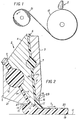
- Figs. 1 and 2 show schematically, and not to scale, an apparatus of the invention comprising a casting substrate 12 and a novel cocasting die 2 which is positioned above and close to the substrate.
- the substrate is adapted to move continuously in the downstream direction indicated by arrow 1.
- the substrate 12 can be a polished metal belt or drum or a polymeric belt. A continuous belt of a polymer such as poly(ethylene terephthalate) is preferred.
- Substrate 12 provides the surface on which the liquid casting compositions or dopes are cast simultaneously and from which the cast film, after evaporation of the volatile casting solvent, is stripped and wound as roll 21.
- the novel die 2 is of a structure that makes possible the casting of films of two or more layers of widely differing thicknesses and from casting compositions or dopes of widely differing viscosities. Despite these differences in thicknesses and viscosities - which are obstacles to conventional cocasting methods - the novel apparatus and method can simultaneously cast two or more layers precisely and with uniform thicknesses.
- Films which are made by the apparatus and method of the invention are plural layer polymeric films. They include, for example, magnetic recording films and photographic film supports. These typically comprise a substrate layer such as cellulose triacetate and one or more of certain functional layers. In photographic film supports a functional layer can be, for example, a subbing layer to improve adhesion of light sensitive layers to the substrate. In magnetic recording films, e.g., as disclosed in the patent to Krall, U.S. 3,782,947, the substrate also can be cellulose triacetate and the functional layer can be a dispersion of magnetic particles, e.g., iron oxide particles, in a cellulose ester.
- magnetic recording films e.g., as disclosed in the patent to Krall, U.S. 3,782,947
- the substrate also can be cellulose triacetate and the functional layer can be a dispersion of magnetic particles, e.g., iron oxide particles, in a cellulose ester.
- the surface uniformity of photographic substrate films is important for the uniform coating of light sensitive layers. It is also important for magnetic recording films to provide accurate signal recording. The uniform thicknesses of the layers is also important for providing the required physical properties of the films.
- the substrate or support for such films is normally cast from a dope comprising a solution of a polymer, e.g., a cellulose ester, in a volatile solvent, e.g., methylene chloride or a mixture of methylene chloride, methanol and cyclohexane It can, contain optional addenda such as dissolved dyes, dispersed pigments or flow agents.
- a polymer e.g., a cellulose ester
- a volatile solvent e.g., methylene chloride or a mixture of methylene chloride, methanol and cyclohexane
- the functional layer or layers are also cast from dopes; however, their dopes do not necessarily contain the same polymers and the same solvents as the support layer.
- the dopes can additionally contain, either dispersed or dissolved therein, components that impart the required functionality to the layers.
- the dope can contain iron oxide.
- the functional layer dopes are of a lower polymer concentration than the support layer dope and of lower viscosity.
- the method and apparatus of the invention are suitable for casting any such polymeric solutions and dispersions and any of the casting compositions disclosed in U.S. Patent Nos. 3,782,947 and 2,932,855, cited above, both of which are incorporated herein by reference.
- arrow 1 designates the downstream direction, the direction in which the two-layer film is formed.
- the die assembly 2 includes three elements: a cover 3, a pie 4 and a body 5.
- Cover 3, pie 4 and body 5 are coextensive and have a length that is determined by the width of the film being cast. This can be from a few centimeters to one or more meters.
- Cover 3, pie 4, and body 5 are held in spaced relationship to one another by a pair of end plates (not shown).
- the die elements can be held in the spaced relationship by a system of lands and through-bolts as is well known in the art.
- End plates though not structural, are used to seal the ends of the die.
- the space so defined, includes a dope inlet 6, a distribution cavity 7 and a slot 8 which is formed by the narrowly spaced-apart parallel walls 22 and 23.
- pie 4 and body 5 are spaced apart to include dope inlet 9, distribution cavity 10 and a slot 11 which is formed by the narrowly spaced-apart parallel walls 24 and 25.
- Inlets 6 and 9 admit dope under pressure.
- Distribution cavities 7 and 10 act as flow eveners or buffers to assure laminar flow in slots 8 and 11.
- the casting substrate 12 can be a polymeric belt or a polished metal belt or drum from which the cast film can be stripped after sufficient solvent is evaporated or it can be a film on which two or more additional layers can be cast.
- the die 2 is so positioned that the slot exits are spaced above and close to the substrate 12.
- the exact spacing of the die from the casting surface can vary according to the process conditions.
- a typical spacing or distance of the lowermost lands of the slots from the substrate is in the range from 0.1 to 3 mm and preferably from 0.5 to 1,5 mm.
- the slots 8 and 11 extend from cavities 7 and 10, respectively, to lips which form elongated and mutually parallel slot exits 27 and 28, respectively.
- the long dimensions of the slot exits are perpendicular to the direction of movement of the substrate 12.
- the upstream slot exit 27 has an outer lip formed by the planar rectangular land 15 which is coextensive with, i.e., of the same length as, the slot exit.
- Slot exit 27 has an inner lip formed by the narrow elongated land 14 which is coplanar and coextensive in length with land 15.
- the plane of land 15 forms an acute angle with the planar upstream wall 24 of slot 11. This contributes to the successful coating of layers that are of uniform but different thicknesses.
- the downstream slot 8 has a slot exit 28 which has a first lip formed by land 14, which is coplanar with the inner lip of slot exit 27 since it is the same land.
- the innermost lips of, say, the first and third slot exits would not be identical but would still be coplanar.
- the downstream slot exit 28 has a second lip formed by the downstream, planar, rectangular land 13. This land is coextensive in length with slot exit 28 and extends in its widthwise or downstream direction to a pinning line 16 which is formed by the intersection of land 13 with the downstream outer surface 29 of the die.
- Slot 8 terminates in lands 13 and 14 which are coextensive in length with slot 8 and are parallel to the casting surface 12. Land 13, however, is at a greater distance from casting substrate 12 than is land 14, the additional distance being called the offset.
- Dope flowing from slot 8 wets land 13 and separates sharply from the die at pinning line 16.
- the width of the downstream land 13 is less than that of the upstream land 15 and, most preferably, is less than the width of all of the other lands.
- the short distance from the slot to the pinning line 16 contributes to formation of a thin top or functional layer.
- the exact width of land 13 and the magnitude of the offset are selected according to the dope viscosity, the dope flow rate and the spacing of the die from casting surface 12. Typical values are illustrated in the Examples hereinafter.
- pinning line 17 defines the boundary between the dopes flowing from slots 8 and 11.
- pinning line 18 defines the boundary between the dopes flowing from slots 8 and 11.
- the exterior angle between land 15 and outer surface 21 is greater than 180 degrees and preferably is greater than 200 degrees. This ensures that the dope from slot 11 does not flow past the pinning line 18.
- a groove can be provided at the pinning line in said outer surface to form an exterior angle greater than said 180 degrees.
- the dope of support layer 19, which can be highly viscous is admitted at inlet 9, flow-stabilized in cavity 10 and extruded through slot 11.
- the dope of functional layer 20, which can be much less viscous than the dope of layer 19 is admitted at inlet 6, flow-stabilized in cavity 7 and extruded through slot 8.
- the viscous support-layer dope flowing through slot 11 is normally under higher pressure than is the functional layer dope flowing through slot 8, and slot 11 preferably is wider than slot 8. It is also a characteristic of the preferred embodiment of the apparatus of the invention that land 13 is wider than its adjacent slot 8 and land 18 is of substantially the same width as its adjacent slot 11.
- pie 4 and body 5 have to be strong enough to resist bending and corresponding widening of slot 11 between the end plates of the die.
- the angle between slots 11 and 8 preferably is at least 32 degrees.
- the angle between die body face 21 and slot 11 preferably is at least 32 degrees.
- the interior angle between the plane of slot 8 and the downstream direction of the casting surface 12 is greater than 90° degrees. This contributes to the formation of layers of the desired uniformity.
- Fig. 2 shows only two slots in the die
- the apparatus of the invention can include dies for cocasting more than two layers.
- additional slots and lands can be provided to cocast a support layer and two functional layers, said functional layers being either on the same side or on opposite sides of the support layer.
- a support layer dope having a viscosity of 100,000 millipascal seconds was prepared from cellulose triacetate at a 20% solids concentration in a solvent blend of methylene chloride, methyl alcohol and butyl alcohol.
- a functional layer dope having a viscosity of 125 millipascal seconds was prepared from cellulose triacetate at a 4% concentration in a solvent blend of methylene chloride and methyl alcohol; the functional layer dope also contained nigrosine dye to provide optical density for uniformity analysis.
- the support layer dope was pumped through inlet 9, distribution cavity 10 and slot 11 at a rate that provided a dried support layer thickness of 0.102 mm (0.004 inches).
- the functional layer dope was pumped through inlet 6, cavity 7 and slot 8 at rates that provided dried functional layer thicknesses varying in steps from 1.27 ⁇ m to 3.81 ⁇ m.
- This comparative example demonstrates that when cocasting with a die in which the downstream land 13 was in the same plane as the other lands, and when the casting dopes differed widely in viscosity (100,000 vs. 125 mPa.s) and the cast layer thicknesses differed widely (0.102 mm vs. 1.27 - 3.81 ⁇ m), an unacceptable film was produced.
- Examples 1, 2 and 3 show that although the dope viscosities and the layer thicknesses differed widely as they also did in the unsatisfactory Comparative Example, a film of good quality was obtained with the cocasting die of the invention in which the downstream land 13 was offset above the other lands and was more narrow than the upstream land 15.
Landscapes
- Engineering & Computer Science (AREA)
- Mechanical Engineering (AREA)
- Manufacturing & Machinery (AREA)
- Moulding By Coating Moulds (AREA)
- Extrusion Moulding Of Plastics Or The Like (AREA)
Claims (10)
- Vorrichtung zur Herstellung polymerer Filme mit mindestens zwei Schichten (19, 20), mita) einem Gießsubstrat (12), das eine kontinuierlich stromabwärts bewegbare, äußere Fläche aufweist,b) einer gemeinsamen Spritzgußform (2) zum gleichzeitigen Extrudieren von mindestens zwei Gießzusammensetzungen in einander benachbarten Schichten auf das sich bewegende Substrat, wobei
die Spritzgußform eine stromaufwärts und eine stromabwärts gerichtete Seite aufweist und eine Gruppe von Elementen umfaßt, die einen stromaufwärts gerichteten Extrusionsschlitz (27) auf der stromaufwärts gerichteten Seite sowie einen stromabwärts gerichteten Extrusionsschlitz (28) auf der stromabwärts gerichteten Seite der Spritzgußform aufweisen,
die Spritzgußform eine Vielzahl von Öffnungen (10, 7) aufweist zum Aufnehmen von Gießzusammensetzungen und zum Transportieren der Zusammensetzungen mit konstanter Geschwindigkeit zu den jeweiligen Extrusionsschlitzen,
jeder Extrusionsschlitz in geringem Abstand voneinander angeordnete parallele Wände (24, 25, 23, 22) umfaßt, die sich von den Öffnungen bis hin zu langgestreckte Schlitzausgänge bildenden Rändern erstrecken, wobei die Schlitzausgänge wechselseitig parallel zueinander zur äußeren Fläche des Gießsubstrats verlaufen,
die Spritzgußform derart angeordnet ist, daß die Schlitzausgänge in geringem Abstand vom Gießsubstrat vorgesehen sind, wobei sich die langen Abmessungen der Schlitzausgänge senkrecht zur Bewegungsrichtung des Gießsubstrats erstrecken,
der stromaufwärts gerichtete Schlitzausgang (27) einen äußeren Rand mit einer ersten äußeren, flachen, rechteckigen Formtrennfläche (15) und einen zweiten inneren Rand aufweist, der von einer zweiten inneren engen, langgestreckten Formtrennfläche (14) gebildet ist, wobei die erste äußere, flache, rechteckige Formtrennfläche (15) mit der stromaufwärts gerichteten parallelen Wand (24) einen spitzen Winkel bildet und sich in der Breite in stromaufwärts gerichteter Richtung bis hin zu einer Verbindungslinie (18) erstreckt, die durch den Schnittpunkt von Trennfläche und einer stromaufwärts gerichteten, äußeren Fläche (21) der Spritzgußform in einem äußeren Winkel von mehr als 180° gebildet ist, und wobei
auf der stromabwärts gerichteten Seite der Spritzgußform ein stromabwärts gerichteter Schlitzausgang (28) mit einem dritten, stromaufwärts gerichteten, von einer dritten flachen, rechteckigen Trennfläche (14) gebildeten Rand und mit einem vierten, stromabwärts gerichteten, von einer vierten, stromabwärts gerichteten, flachen, rechteckigen Trennfläche (13) gebildeten Rand versehen ist, wobei sich die stromabwärts gerichtete Trennfläche längenmäßig in der gleichen Richtung erstreckt wie der stromabwärts gerichtete Schlitzausgang und sich in der Breite bis hin zu einer Verbindungslinie (16) erstreckt, die durch den Schnittpunkt mit einer anderen stromabwärts gerichteten, äußeren Fläche (29) der Spritzgußform gebildet ist,
dadurch gekennzeichnet, daß
die erste äußere, flache, rechteckige Trennfläche (15) und die zweite innere, enge, langgestreckte Trennfläche (14) koplanar zueinander verlaufen und sich in der gleichen Richtung erstrecken wie der stromaufwärts gerichtete Schlitz,
die dritte flache, rechteckige Trennfläche (14) sich in der gleichen Richtung wie die erste äußere, flache, rechteckige Trennfläche (15) und koplanar dazu erstreckt und daß die Ebene der vierten, stromabwärts gerichteten, planen, rechteckigen Trennfläche (13) im wesentlichen parallel zur Ebene der ersten äußeren, flachen, rechteckigen Trennfläche verläuft, und daß
die vierte, stromabwärts gerichtete Trennfläche in einem größeren Abstand vom Gießsubstrat angeordnet ist als die anderen Trennflächen. - Vorrichtung nach Anspruch 1, dadurch gekennzeichnet, daß die zweite Trennfläche des stromaufwärts gerichteten Schlitzausgangs den dritten Rand des stromabwärts gerichteten Schlitzausgangs bildet.
- Vorrichtung nach Anspruch 1 oder 2, dadurch gekennzeichnet, daß die stromaufwärts gerichtete äußere Fläche (21) der Spritzgußform die erste flache, rechteckige Trennfläche (15) in einem äußeren Winkel von mehr als 200° schneidet.
- Vorrichtung nach einem der Ansprüche 1 bis 3, dadurch gekennzeichnet, daß die stromabwärts gerichtete Trennfläche (13) schmaler ist als die anderen Trennflächen (14, 15).
- Vorrichtung nach einem der Ansprüche 1 bis 4, dadurch gekennzeichnet, daß die stromabwärts gerichtete Trennfläche (13) schmaler ist als die erste flache, rechteckige Trennfläche (15).
- Vorrichtung nach einem der Ansprüche 1 bis 5, dadurch gekennzeichnet, daß der spitze Winkel zwischen der ersten flachen, rechteckigen Trennfläche (15) und der flachen, stromaufwärts gerichteten Wand (24) des Schlitzes mindestens 32° beträgt.
- Vorrichtung nach einem der Ansprüche 1 bis 6, dadurch gekennzeichnet, daß der Winkel zwischen der flachen Fläche des Gießsubstrats (12) und der planen Wand (22, 23) des stromaufwärts gerichteten Schlitzes (8) mindestens 90° beträgt.
- Verfahren zum gleichzeitigen Gießen flüssiger polymerer Gießzusammensetzungen aus einem Polymer und einer flüchtigen Flüssigkeit als aneinandergrenzende Schichten auf ein bewegbares Substrat mittels einer eine Vielzahl von Extrusionsschlitzen aufweisenden Preßform, um einen polymeren Film aus Schichten gleichförmiger, jedoch unterschiedlicher Dicke herzustellen, wobei
erste und zweite flüssige polymere Gießzusammensetzungen zu einem ersten relativ breiten bzw. einem zweiten relativ engen Extrusionsschlitz in der Spritzgußform transportiert werden, wobei die Spritzgußform derart bezüglich des sich bewegenden Substrats angeordnet ist, daß sich der relativ enge Extrusionsschlitz stromabwärts vom relativ breiten Extrusionsschlitz befindet,
dadurch gekennzeichnet, daß
die flüchtige Flüssigkeit oder eine verdünnte Mischung daraus vor dem Transport der Gießzusammensetzungen mit dem Polymer zu den Schlitzen gefördert wird, anschließend die erste Gießzusammensetzung so lange zu dem relativ breiten Schlitz transportiert wird, bis sich ein gleichförmiger Strom gebildet hat, der in Berührung mit einer Verbindungslinie entlang einer Trennfläche stromaufwärts vom relativ breiten Schlitz steht, und dann die erste Gießzusammensetzung als Zufuhr zum relativ engen Schlitz ersetzt wird. - Verfahren nach Anspruch 8, dadurch gekennzeichnet, daß die Gießzusammensetzungen ein zelluloses Polymer und ein flüchtiges Lösungsmittel aufweisen und daß das flüchtige Lösungsmittel noch vor den Gießzusammensetzungen zu den Extrusionsschlitzen gefördert wird.
- Verfahren nach Anspruch 9, dadurch gekennzeichnet, daß eine erste Gießzusammensetzung eine höhere Viskosität aufweist und mit höherer Fließgeschwindigkeit als eine zweite Gießzusammensetzung transportiert wird.
Applications Claiming Priority (2)
| Application Number | Priority Date | Filing Date | Title |
|---|---|---|---|
| US890507 | 1992-05-28 | ||
| US07/890,507 US5256357A (en) | 1992-05-28 | 1992-05-28 | Apparatus and method for cocasting film layers |
Publications (2)
| Publication Number | Publication Date |
|---|---|
| EP0572329A1 EP0572329A1 (de) | 1993-12-01 |
| EP0572329B1 true EP0572329B1 (de) | 1997-07-16 |
Family
ID=25396775
Family Applications (1)
| Application Number | Title | Priority Date | Filing Date |
|---|---|---|---|
| EP93420197A Expired - Lifetime EP0572329B1 (de) | 1992-05-28 | 1993-05-17 | Vorrichtung und Verfahren zum gleichzeitigen Strangpressen von dünnen Schichten |
Country Status (4)
| Country | Link |
|---|---|
| US (1) | US5256357A (de) |
| EP (1) | EP0572329B1 (de) |
| JP (1) | JPH0631789A (de) |
| DE (1) | DE69312172T2 (de) |
Cited By (1)
| Publication number | Priority date | Publication date | Assignee | Title |
|---|---|---|---|---|
| EP4148815A4 (de) * | 2020-09-17 | 2023-12-13 | LG Energy Solution, Ltd. | Doppelschlitzdüsenbeschichter und verfahren zur aufschlämmungsbeschichtung von elektrodenaktivmaterial damit |
Families Citing this family (36)
| Publication number | Priority date | Publication date | Assignee | Title |
|---|---|---|---|---|
| US5741549A (en) * | 1994-04-29 | 1998-04-21 | Maier; Gary W. | Slide die coating method and apparatus with improved die lip |
| US5639305A (en) * | 1994-04-29 | 1997-06-17 | Minnesota Mining And Manufacturing Company | Die coating method and apparatus |
| US5759274A (en) * | 1994-04-29 | 1998-06-02 | Minnesota Mining And Manufacturing Company | Die coating apparatus with surface covering |
| US5728430A (en) * | 1995-06-07 | 1998-03-17 | Avery Dennison Corporation | Method for multilayer coating using pressure gradient regulation |
| US6824828B2 (en) | 1995-06-07 | 2004-11-30 | Avery Dennison Corporation | Method for forming multilayer release liners |
| US5962075A (en) * | 1995-06-07 | 1999-10-05 | Avery Dennison | Method of multilayer die coating using viscosity adjustment techniques |
| US5747107A (en) * | 1995-10-26 | 1998-05-05 | Minnesota Mining And Manufacturing Company | Method of applying a hot melt coating |
| NL1009107C2 (nl) * | 1997-11-12 | 1999-06-15 | Banner Pharmacaps Inc | Gelatine-uitspreidende doos met meervoudige, aanpasbare poortklep en meerlagig zacht gel. |
| US7942274B2 (en) * | 2000-05-24 | 2011-05-17 | Millipore Corporation | High-throughput asymmetric membrane |
| EP1834692B1 (de) * | 2000-05-24 | 2017-02-22 | EMD Millipore Corporation | Mehrschichtige Membranen |
| EP2324906B1 (de) * | 2000-05-24 | 2014-09-10 | EMD Millipore Corporation | Mehrschichtige Membranen |
| US7229665B2 (en) * | 2001-05-22 | 2007-06-12 | Millipore Corporation | Process of forming multilayered structures |
| WO2002011868A1 (en) | 2000-08-07 | 2002-02-14 | Cuno, Inc. | Unsupported multizone microporous membrane |
| US6994789B2 (en) * | 2000-08-07 | 2006-02-07 | Cuno Incorporated | Pre-metered, unsupported multilayer microporous membrane |
| US6736971B2 (en) * | 2000-08-07 | 2004-05-18 | Cuno Incorporated | Pre-metered, unsupported multilayer microporous membrane |
| US7083752B2 (en) | 2002-05-20 | 2006-08-01 | Eastman Kodak Company | Cellulose acetate films prepared by coating methods |
| US20030215583A1 (en) * | 2002-05-20 | 2003-11-20 | Eastman Kodak Company | Sulfone films prepared by coating methods |
| US20030215581A1 (en) * | 2002-05-20 | 2003-11-20 | Eastman Kodak Company | Polycarbonate films prepared by coating methods |
| US20030215582A1 (en) * | 2002-05-20 | 2003-11-20 | Eastman Kodak Company | Optical films prepared by coating methods |
| US7163738B2 (en) * | 2002-05-20 | 2007-01-16 | Eastman Kodak Company | Polyvinyl alcohol films prepared by coating methods |
| US7048823B2 (en) | 2002-05-20 | 2006-05-23 | Eastman Kodak Company | Acrylic films prepared by coating methods |
| US7012746B2 (en) | 2002-05-20 | 2006-03-14 | Eastman Kodak Company | Polyvinyl butyral films prepared by coating methods |
| US7085444B2 (en) * | 2003-02-25 | 2006-08-01 | Eastman Kodak Company | Porous optical switch films |
| US7279060B2 (en) * | 2004-05-04 | 2007-10-09 | Eastman Kodak Company | Guarded cover film for LCD polarizers |
| US7252733B2 (en) * | 2004-05-04 | 2007-08-07 | Eastman Kodak Company | Polarizer guarded cover sheet with adhesion promoter |
| US20060068128A1 (en) * | 2004-09-30 | 2006-03-30 | Eastman Kodak Company | Optical films and process for making them |
| US7713595B2 (en) * | 2005-10-18 | 2010-05-11 | Nitto Denko Corporation | Optical compensation films produced by a carrier-web-casting process |
| US7655289B2 (en) * | 2005-12-12 | 2010-02-02 | Eastman Kodak Company | Optical film composite having spatially controlled adhesive strength |
| CA2691052A1 (en) | 2007-06-27 | 2008-12-31 | Sekisui Chemical Co., Ltd. | Apparatus and method for manufacturing multiplex interlayer for safety glass |
| US8221298B2 (en) * | 2008-07-21 | 2012-07-17 | Paragon Films, Inc. | Apparatus and method for folding film edges |
| US8858211B2 (en) * | 2011-01-31 | 2014-10-14 | Premier Dies Corporation | Liquid coating die |
| JP5346972B2 (ja) * | 2011-03-30 | 2013-11-20 | 富士フイルム株式会社 | 被膜付きフィルムの製造方法 |
| US9444106B2 (en) * | 2013-03-15 | 2016-09-13 | GM Global Technology Operations LLC | Simultaneous coating of fuel cell components |
| US9656321B2 (en) | 2013-05-15 | 2017-05-23 | General Electric Company | Casting method, cast article and casting system |
| KR20150137447A (ko) | 2014-05-29 | 2015-12-09 | 삼성전자주식회사 | 필름 제조용 슬롯 다이 |
| FR3086198B1 (fr) * | 2018-09-20 | 2022-01-28 | Michelin & Cie | Machine de coextrusion pour melanges elastomeriques |
Family Cites Families (15)
| Publication number | Priority date | Publication date | Assignee | Title |
|---|---|---|---|---|
| US2679661A (en) * | 1949-07-21 | 1954-06-01 | Celanese Corp | Method and apparatus for forming films |
| CA557259A (en) * | 1955-02-23 | 1958-05-13 | Canadian Kodak Co. Limited | Multiple layer hopper for multiply coating a web |
| US2901770A (en) * | 1955-05-06 | 1959-09-01 | Du Pont | Extrusion apparatus and processes of extruding |
| NL220653A (de) * | 1956-09-11 | 1900-01-01 | ||
| US3038209A (en) * | 1958-07-10 | 1962-06-12 | Eastman Kodak Co | Method of dope-casting film at high shear rate |
| US3302239A (en) * | 1963-05-24 | 1967-02-07 | Du Pont | Die |
| JPS4917853B1 (de) * | 1965-11-16 | 1974-05-04 | ||
| GB1208809A (en) * | 1968-09-30 | 1970-10-14 | Agfa Gevaert Ag | Process and apparatus for casting a plurality of photographic emulsion layers on continuously moving substrates |
| US3782947A (en) * | 1972-01-28 | 1974-01-01 | Eastman Kodak Co | Photographic product with photographically transparent magnetic recording medium |
| DE2614596C3 (de) * | 1976-04-05 | 1980-03-13 | Vereinigte Glaswerke Gmbh, 5100 Aachen | Abstreichgießkopf zum Aufbringen gießfähiger Kunststoffschichten auf plane Unterlagen |
| JPS6050511B2 (ja) * | 1978-09-20 | 1985-11-08 | 富士写真フイルム株式会社 | 織目模様形成方法 |
| US4246335A (en) * | 1979-04-09 | 1981-01-20 | W. R. Grace & Co. | Shape dispensing of photopolymer |
| JPS56162617A (en) * | 1980-05-20 | 1981-12-14 | Fuji Photo Film Co Ltd | Preparation of film |
| JPH0677711B2 (ja) * | 1986-07-15 | 1994-10-05 | 富士写真フイルム株式会社 | 塗布装置 |
| JPH0649171B2 (ja) * | 1988-07-04 | 1994-06-29 | 富士写真フイルム株式会社 | 塗布方法 |
-
1992
- 1992-05-28 US US07/890,507 patent/US5256357A/en not_active Expired - Lifetime
-
1993
- 1993-05-17 DE DE69312172T patent/DE69312172T2/de not_active Expired - Fee Related
- 1993-05-17 EP EP93420197A patent/EP0572329B1/de not_active Expired - Lifetime
- 1993-05-24 JP JP5121018A patent/JPH0631789A/ja active Pending
Cited By (3)
| Publication number | Priority date | Publication date | Assignee | Title |
|---|---|---|---|---|
| EP4148815A4 (de) * | 2020-09-17 | 2023-12-13 | LG Energy Solution, Ltd. | Doppelschlitzdüsenbeschichter und verfahren zur aufschlämmungsbeschichtung von elektrodenaktivmaterial damit |
| EP4512537A3 (de) * | 2020-09-17 | 2025-05-07 | LG Energy Solution, Ltd. | Doppelschlitzdüsenbeschichter und verfahren zur beschichtung einer elektrodenaktivmaterialaufschlämmung unter verwendung davon |
| US12420303B2 (en) | 2020-09-17 | 2025-09-23 | Lg Energy Solution, Ltd. | Dual slot die coater and method for coating electrode active material slurry using the same |
Also Published As
| Publication number | Publication date |
|---|---|
| JPH0631789A (ja) | 1994-02-08 |
| US5256357A (en) | 1993-10-26 |
| EP0572329A1 (de) | 1993-12-01 |
| DE69312172T2 (de) | 1998-01-08 |
| DE69312172D1 (de) | 1997-08-21 |
Similar Documents
| Publication | Publication Date | Title |
|---|---|---|
| EP0572329B1 (de) | Vorrichtung und Verfahren zum gleichzeitigen Strangpressen von dünnen Schichten | |
| US4828779A (en) | Coating method | |
| US2761418A (en) | Multiple coating apparatus | |
| US4324816A (en) | Method for forming a stripe by extrusion coating | |
| US5030484A (en) | Coating method | |
| US4681062A (en) | Coating apparatus | |
| JP2581975B2 (ja) | 塗布装置 | |
| EP0104089B1 (de) | Gleichzeitige Herstellung und Absetzung von streifenartigen Strömen | |
| EP0003860B1 (de) | Verfahren zur Beschichtung einer Materialbahn mit mehreren übereinander angeordneten photographischen Schichten, nach dem Vorhang-Beschichtungs-Verfahren | |
| US4518637A (en) | Coating solution metering method and apparatus | |
| US3526528A (en) | Multiple doctor coating process and apparatus | |
| US4907530A (en) | Apparatus for applying a liquid to a support | |
| US4863765A (en) | Method of multi-layer coating | |
| EP0018029B1 (de) | Verfahren und Vorrichtung zur Mehrfachbegiessung mit einem Gleittrichter | |
| GB1582485A (en) | Process for coating a liquid on a travelling web | |
| DE3434240C2 (de) | ||
| CN1174523A (zh) | 多层涂覆的方法 | |
| JPS635151B2 (de) | ||
| CA2209939C (en) | Slot coating method and apparatus | |
| US5614260A (en) | Extrusion system with slide dies | |
| JP2630522B2 (ja) | 塗布方法及び装置 | |
| US5376178A (en) | Coating apparatus | |
| US5922408A (en) | Coating method using extrusion die having predetermined gap | |
| JPH08505487A (ja) | 磁気記録担体を製造するための装置 | |
| US4921729A (en) | Two-layer coating method |
Legal Events
| Date | Code | Title | Description |
|---|---|---|---|
| PUAI | Public reference made under article 153(3) epc to a published international application that has entered the european phase |
Free format text: ORIGINAL CODE: 0009012 |
|
| AK | Designated contracting states |
Kind code of ref document: A1 Designated state(s): BE DE FR GB NL |
|
| 17P | Request for examination filed |
Effective date: 19940519 |
|
| 17Q | First examination report despatched |
Effective date: 19951020 |
|
| GRAG | Despatch of communication of intention to grant |
Free format text: ORIGINAL CODE: EPIDOS AGRA |
|
| GRAH | Despatch of communication of intention to grant a patent |
Free format text: ORIGINAL CODE: EPIDOS IGRA |
|
| GRAH | Despatch of communication of intention to grant a patent |
Free format text: ORIGINAL CODE: EPIDOS IGRA |
|
| GRAA | (expected) grant |
Free format text: ORIGINAL CODE: 0009210 |
|
| AK | Designated contracting states |
Kind code of ref document: B1 Designated state(s): BE DE FR GB NL |
|
| REF | Corresponds to: |
Ref document number: 69312172 Country of ref document: DE Date of ref document: 19970821 |
|
| ET | Fr: translation filed | ||
| PLBE | No opposition filed within time limit |
Free format text: ORIGINAL CODE: 0009261 |
|
| STAA | Information on the status of an ep patent application or granted ep patent |
Free format text: STATUS: NO OPPOSITION FILED WITHIN TIME LIMIT |
|
| 26N | No opposition filed | ||
| REG | Reference to a national code |
Ref country code: GB Ref legal event code: IF02 |
|
| PGFP | Annual fee paid to national office [announced via postgrant information from national office to epo] |
Ref country code: GB Payment date: 20050406 Year of fee payment: 13 |
|
| PGFP | Annual fee paid to national office [announced via postgrant information from national office to epo] |
Ref country code: NL Payment date: 20050407 Year of fee payment: 13 |
|
| PGFP | Annual fee paid to national office [announced via postgrant information from national office to epo] |
Ref country code: FR Payment date: 20050517 Year of fee payment: 13 |
|
| PGFP | Annual fee paid to national office [announced via postgrant information from national office to epo] |
Ref country code: BE Payment date: 20050527 Year of fee payment: 13 |
|
| PGFP | Annual fee paid to national office [announced via postgrant information from national office to epo] |
Ref country code: DE Payment date: 20050531 Year of fee payment: 13 |
|
| PG25 | Lapsed in a contracting state [announced via postgrant information from national office to epo] |
Ref country code: GB Free format text: LAPSE BECAUSE OF NON-PAYMENT OF DUE FEES Effective date: 20060517 |
|
| PG25 | Lapsed in a contracting state [announced via postgrant information from national office to epo] |
Ref country code: BE Free format text: LAPSE BECAUSE OF NON-PAYMENT OF DUE FEES Effective date: 20060531 |
|
| PG25 | Lapsed in a contracting state [announced via postgrant information from national office to epo] |
Ref country code: NL Free format text: LAPSE BECAUSE OF NON-PAYMENT OF DUE FEES Effective date: 20061201 Ref country code: DE Free format text: LAPSE BECAUSE OF NON-PAYMENT OF DUE FEES Effective date: 20061201 |
|
| GBPC | Gb: european patent ceased through non-payment of renewal fee |
Effective date: 20060517 |
|
| NLV4 | Nl: lapsed or anulled due to non-payment of the annual fee |
Effective date: 20061201 |
|
| REG | Reference to a national code |
Ref country code: FR Ref legal event code: ST Effective date: 20070131 |
|
| BERE | Be: lapsed |
Owner name: *EASTMAN KODAK CY Effective date: 20060531 |
|
| PG25 | Lapsed in a contracting state [announced via postgrant information from national office to epo] |
Ref country code: FR Free format text: LAPSE BECAUSE OF NON-PAYMENT OF DUE FEES Effective date: 20060531 |