EP0572320A2 - Ruban en polytétrafluoroéthylène apte au marquage par laser - Google Patents
Ruban en polytétrafluoroéthylène apte au marquage par laser Download PDFInfo
- Publication number
- EP0572320A2 EP0572320A2 EP93401347A EP93401347A EP0572320A2 EP 0572320 A2 EP0572320 A2 EP 0572320A2 EP 93401347 A EP93401347 A EP 93401347A EP 93401347 A EP93401347 A EP 93401347A EP 0572320 A2 EP0572320 A2 EP 0572320A2
- Authority
- EP
- European Patent Office
- Prior art keywords
- ptfe
- ribbon
- layers
- raw
- tape
- Prior art date
- Legal status (The legal status is an assumption and is not a legal conclusion. Google has not performed a legal analysis and makes no representation as to the accuracy of the status listed.)
- Granted
Links
Images
Classifications
-
- B—PERFORMING OPERATIONS; TRANSPORTING
- B32—LAYERED PRODUCTS
- B32B—LAYERED PRODUCTS, i.e. PRODUCTS BUILT-UP OF STRATA OF FLAT OR NON-FLAT, e.g. CELLULAR OR HONEYCOMB, FORM
- B32B7/00—Layered products characterised by the relation between layers; Layered products characterised by the relative orientation of features between layers, or by the relative values of a measurable parameter between layers, i.e. products comprising layers having different physical, chemical or physicochemical properties; Layered products characterised by the interconnection of layers
- B32B7/02—Physical, chemical or physicochemical properties
- B32B7/023—Optical properties
-
- B—PERFORMING OPERATIONS; TRANSPORTING
- B32—LAYERED PRODUCTS
- B32B—LAYERED PRODUCTS, i.e. PRODUCTS BUILT-UP OF STRATA OF FLAT OR NON-FLAT, e.g. CELLULAR OR HONEYCOMB, FORM
- B32B27/00—Layered products comprising a layer of synthetic resin
- B32B27/06—Layered products comprising a layer of synthetic resin as the main or only constituent of a layer, which is next to another layer of the same or of a different material
- B32B27/08—Layered products comprising a layer of synthetic resin as the main or only constituent of a layer, which is next to another layer of the same or of a different material of synthetic resin
-
- B—PERFORMING OPERATIONS; TRANSPORTING
- B32—LAYERED PRODUCTS
- B32B—LAYERED PRODUCTS, i.e. PRODUCTS BUILT-UP OF STRATA OF FLAT OR NON-FLAT, e.g. CELLULAR OR HONEYCOMB, FORM
- B32B27/00—Layered products comprising a layer of synthetic resin
- B32B27/32—Layered products comprising a layer of synthetic resin comprising polyolefins
- B32B27/322—Layered products comprising a layer of synthetic resin comprising polyolefins comprising halogenated polyolefins, e.g. PTFE
-
- B—PERFORMING OPERATIONS; TRANSPORTING
- B41—PRINTING; LINING MACHINES; TYPEWRITERS; STAMPS
- B41M—PRINTING, DUPLICATING, MARKING, OR COPYING PROCESSES; COLOUR PRINTING
- B41M5/00—Duplicating or marking methods; Sheet materials for use therein
- B41M5/26—Thermography ; Marking by high energetic means, e.g. laser otherwise than by burning, and characterised by the material used
- B41M5/267—Marking of plastic artifacts, e.g. with laser
-
- B—PERFORMING OPERATIONS; TRANSPORTING
- B32—LAYERED PRODUCTS
- B32B—LAYERED PRODUCTS, i.e. PRODUCTS BUILT-UP OF STRATA OF FLAT OR NON-FLAT, e.g. CELLULAR OR HONEYCOMB, FORM
- B32B2307/00—Properties of the layers or laminate
- B32B2307/40—Properties of the layers or laminate having particular optical properties
- B32B2307/402—Coloured
-
- B—PERFORMING OPERATIONS; TRANSPORTING
- B32—LAYERED PRODUCTS
- B32B—LAYERED PRODUCTS, i.e. PRODUCTS BUILT-UP OF STRATA OF FLAT OR NON-FLAT, e.g. CELLULAR OR HONEYCOMB, FORM
- B32B2307/00—Properties of the layers or laminate
- B32B2307/70—Other properties
- B32B2307/72—Density
-
- B—PERFORMING OPERATIONS; TRANSPORTING
- B32—LAYERED PRODUCTS
- B32B—LAYERED PRODUCTS, i.e. PRODUCTS BUILT-UP OF STRATA OF FLAT OR NON-FLAT, e.g. CELLULAR OR HONEYCOMB, FORM
- B32B2327/00—Polyvinylhalogenides
- B32B2327/12—Polyvinylhalogenides containing fluorine
- B32B2327/18—PTFE, i.e. polytetrafluoroethylene
-
- Y—GENERAL TAGGING OF NEW TECHNOLOGICAL DEVELOPMENTS; GENERAL TAGGING OF CROSS-SECTIONAL TECHNOLOGIES SPANNING OVER SEVERAL SECTIONS OF THE IPC; TECHNICAL SUBJECTS COVERED BY FORMER USPC CROSS-REFERENCE ART COLLECTIONS [XRACs] AND DIGESTS
- Y10—TECHNICAL SUBJECTS COVERED BY FORMER USPC
- Y10S—TECHNICAL SUBJECTS COVERED BY FORMER USPC CROSS-REFERENCE ART COLLECTIONS [XRACs] AND DIGESTS
- Y10S428/00—Stock material or miscellaneous articles
- Y10S428/906—Roll or coil
-
- Y—GENERAL TAGGING OF NEW TECHNOLOGICAL DEVELOPMENTS; GENERAL TAGGING OF CROSS-SECTIONAL TECHNOLOGIES SPANNING OVER SEVERAL SECTIONS OF THE IPC; TECHNICAL SUBJECTS COVERED BY FORMER USPC CROSS-REFERENCE ART COLLECTIONS [XRACs] AND DIGESTS
- Y10—TECHNICAL SUBJECTS COVERED BY FORMER USPC
- Y10T—TECHNICAL SUBJECTS COVERED BY FORMER US CLASSIFICATION
- Y10T428/00—Stock material or miscellaneous articles
- Y10T428/249921—Web or sheet containing structurally defined element or component
- Y10T428/249953—Composite having voids in a component [e.g., porous, cellular, etc.]
- Y10T428/249987—With nonvoid component of specified composition
- Y10T428/249988—Of about the same composition as, and adjacent to, the void-containing component
-
- Y—GENERAL TAGGING OF NEW TECHNOLOGICAL DEVELOPMENTS; GENERAL TAGGING OF CROSS-SECTIONAL TECHNOLOGIES SPANNING OVER SEVERAL SECTIONS OF THE IPC; TECHNICAL SUBJECTS COVERED BY FORMER USPC CROSS-REFERENCE ART COLLECTIONS [XRACs] AND DIGESTS
- Y10—TECHNICAL SUBJECTS COVERED BY FORMER USPC
- Y10T—TECHNICAL SUBJECTS COVERED BY FORMER US CLASSIFICATION
- Y10T428/00—Stock material or miscellaneous articles
- Y10T428/31504—Composite [nonstructural laminate]
- Y10T428/3154—Of fluorinated addition polymer from unsaturated monomers
- Y10T428/31544—Addition polymer is perhalogenated
Definitions
- the present invention relates to a polytetrafluoroethylene (PTFE) tape formed from at least two layers of polytetrafluoroethylene of different colors, suitable for laser marking.
- PTFE polytetrafluoroethylene
- laser marking consists of making inscriptions on the ribbon by irradiating the ribbon using a laser beam, in particular a CO2 laser.
- a laser beam in particular a CO2 laser.
- perforations are made in the upper layer of the ribbon, allowing the color of the underlying layer to appear in the perforated areas, thereby forming the desired marking.
- the tape in this case provides an insulation function like traditional PTFE tapes and is capable of receiving, by laser marking, identification markings of the cable.
- Known tapes suitable for laser marking, usually comprise a plurality of very thin layers of baked PTFE between which are arranged layers of another fluorinated resin such as FEP and / or PFA, the ribbon itself being coated. FEP and / or PFA.
- the product obtained is therefore particularly expensive.
- the present invention proposes to produce a PTFE tape avoiding these drawbacks and which can moreover be manufactured in a particularly simple and economical manner.
- the tape according to the present invention is formed from at least two layers of PTFE of different colors and is essentially characterized in that the lower layer at least consists of raw PTFE, and that the upper layer at least has a density less than 1.0.
- raw PTFE By raw PTFE is meant PTFE which has never been subjected to cooking at a temperature known as “gelation” or “sintering” which is of the order of 350 ° C.
- the tape comprises only two layers of PTFE, namely an upper layer of low density, less than 1.0, of a first color, for example white in natural PTFE, raw or cooked, possibly with added white pigments, and a lower layer of a second color made of raw PTFE loaded with colored pigments, for example black pigments.
- the ribbon comprises three layers of PTFE, namely an upper layer of a first color, for example white in natural baked PTFE, optionally supplemented with white pigments, an intermediate layer made of PTFE baked loaded with pigments of a second color, for example black pigments, and a lower layer made of raw PTFE loaded with pigments of a third color, different from the second, in particular red pigments, the upper layer and the intermediate layer having a low density less than 1.0.
- a first color for example white in natural baked PTFE
- an intermediate layer made of PTFE baked loaded with pigments of a second color, for example black pigments
- a lower layer made of raw PTFE loaded with pigments of a third color, different from the second, in particular red pigments
- An adjustment of the intensity of the laser beam makes it possible to selectively pierce, either only the upper white layer, or also the intermediate layer, which allows marking in two different colors corresponding respectively to the color of the intermediate layer and of the lower layer .
- Each of the PTFE layers of the ribbon according to the invention can be produced by the known lubricated extrusion process which makes it possible to obtain a ribbon having perfectly controlled characteristics, unlike wet methods, such as those used for obtain the ribbons suitable for known laser marking.
- the lubricated extrusion process consists in mixing PTFE powder with a lubricant to produce a compact preform which is subjected to press spinning in which a piston pushes the PTFE through a die so as to form a profile such as a flat ribbon or a cylindrical rod.
- This profile is then subjected to a calendering operation between two cylinders to obtain a thin tape.
- the lubricant is then removed, in particular by drying, or if necessary using a solvent.
- the ribbon thus obtained can be subjected to a step of dedensification by stretching, for example by passing the ribbon successively over rollers driven at linear peripheral speeds which are in the ratio of the elongation which is wishes to give to the ribbon, or by subjecting the ribbon to the action of a tensioning device which exerts on the ribbon an effort corresponding to the deformation which it is desired to communicate to it.
- the stretching of the ribbon can be carried out after it has been heated.
- the lubricated extrusion process is implemented followed by calendering and, where appropriate, dedensification stretching separately on cylindrical or prismatic preforms formed one of Natural raw PTFE, possibly loaded with white pigments, the other preform (s) being made of raw PTFE, loaded with colored pigments.
- the different layers intended to constitute the ribbon according to the invention are thus obtained separately, in the form of ribbons.
- the layers intended to form the upper layer of the ribbon as well as the intermediate layer or layers can then be baked by being subjected for a sufficient time to a temperature above the sintering temperature.
- a finished layer obtained by the lubricated extrusion process described above can be applied to a layer leaving the calendering rolls and from which the lubricant has not yet been removed.
- part of the lubricant evaporating from the layer which still contains it remains between the two layers of tape and forms an intimate bond of adhesion between the layers.
- the separately extruded layers are calendered together, the ribbon formed is then dried to remove the lubricant and if necessary subjected to a dedensification step.
- the lubricated extrusion process is implemented followed by calendering and, where appropriate, by dedensification stretching on a composite preform, in particular cylindrical or prismatic, having longitudinal zones made up of a mixture of raw PTFE and lubricant, one of the zones containing natural PTFE, if necessary loaded with white or colored pigments and the other zone or zones containing PTFE loaded with colored pigments of different colors.
- the preform may include two semi-cylindrical zones containing, in mixture with a lubricant, one of natural raw PTFE, possibly loaded with white or colored pigments, the other of raw PTFE loaded with colored pigments of different colors.
- a semi-cylindrical mandrel is placed in a cylindrical preform mold, the remaining space of the mold is filled with a first mixture of lubricant and natural PTFE loaded with white or colored pigments, if necessary. This mixture is pushed back using a piston, after which the mandrel is removed and another lubricant and PTFE mixture containing colored pigments of different colors, for example pigments, is placed in the free part of the mold black and a compression is carried out using the piston to compact the two different mixtures contained in the mold.
- layers of raw PTFE of the tape according to the invention may include other additives intended to give the tape special properties, for example carbon black if it is desired to give the tape an additional anti- static.
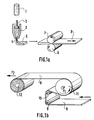
- FIG. 1a illustrates the phases of lubricated extrusion and calendering for producing a layer of raw PTFE tape
- FIG. 1b illustrates the phase, possibly implemented, of dedensification by stretching.
- a preform for example of cylindrical shape, is obtained by compacting a mixture of raw PTFE in fine powder and lubricant.
- the preform 1 is introduced into a spinning press 2 where a piston 3 delivers the mixture of raw PTFE powder and lubricant through a die 4 which, in the example illustrated, is in the form of a slot, so as to obtain a flat ribbon 5.
- the die could be circular so as to obtain a cylindrical rod.
- This ribbon 5 is then brought to pass between two calendering cylinders 6 and 7 rotating in opposite directions so as to obtain a thin ribbon 8.
- the ribbon 8 is dried to remove the lubricant which has served to promote the extrusion and calendering.
- the drying step can be replaced by passing the tape through a solvent to remove the lubricant.
- the ribbon 8 is brought, by means of deflection rollers 9, 10, onto a drum 11 which is rotated at constant speed about its axis in the direction of the arrow F1.
- the drum 11 includes an internal heating device making it possible to maintain its periphery at a constant adjustable temperature.
- the raw PTFE tape 8 After being wound on the periphery of the drum 11, the raw PTFE tape 8 can be wound on a core 12 associated with a device not shown drive, arranged so that the tensile force 2 exerted on the tape can be adjusted at will.
- the ribbon according to the invention can be produced directly by lubricated coextrusion.
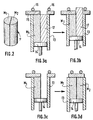
- a preform 1 ′ illustrated in FIG. 2 and formed of two different mixtures M1 and M2 is used.
- the mixture M1 consists of fine powder of natural raw PTFE, optionally added with white pigments, and a lubricant
- the layer M2 is a mixture of a fine powder of raw PTFE added with colored pigments, for example of black pigments, and a lubricant.
- a cylindrical mold 13 is used in which a piston 14 slides.
- the upper part of the mold is selectively closable by a cover 15 held firmly on the mold 13 by support members 16.
- a semi-cylindrical mandrel 17 is placed in the mold and the rest of the cavity is filled.
- mold of a first mixture M1 and the upper part of the mold is closed using the cover 15 directly above the zone containing this mixture M1.
- the piston 14 is actuated so as to repress the mixture M1 after which the mandrel 17 is removed and the free semi-cylindrical space of the mold is filled with a second mixture M2. After completely closing the upper end of the mold, the piston 14 is again actuated so as to cause the compaction of the mixtures M1 and M2. After removing the obturation cover, the preform 1 ′ illustrated in FIG. 2 is obtained which has two semi-cylindrical longitudinal zones containing the mixes M1 and M2 respectively.
- the upper layer of the natural PTFE tape is manufactured, the layer obtained having a thickness of 35 ⁇ m and a density of 0.75.
- the lower layer of the ribbon is produced using raw PTFE loaded at a rate of 1% by weight of black pigments.
- the dedensification step illustrated in FIG. 1b is not carried out.
- the lower layer has a thickness of 50 ⁇ m and a density of 1.60.
- the two layers are associated by pressure.
- the bilayer tape obtained was used in the preparation of a wrapped cable, the dedensified white layer being placed on the outside.
- a ribbon was produced by coextrusion by first producing a preform as illustrated in FIG. 2 using a mixture M1 of raw PTFE and lubricant containing 2% by weight of white pigments and a mixture M2 of raw PTFE and lubricant containing 2% by weight of black pigments.
- the upper layer pigmented in white, has a thickness of 25 ⁇ m.
- This ribbon was densified by stretching so as to reduce its density from 1.58 to 0.80.
- a two-layer tape was produced by combining a baked expanded natural PTFE tape with a density of 0.5 and a thickness of 30 ⁇ m with a raw black pigmented PTFE tape with a density of 1.65 and a thickness of 50 ⁇ m.
- the ribbon obtained has very good laser marking ability.
Landscapes
- Physics & Mathematics (AREA)
- Optics & Photonics (AREA)
- Laminated Bodies (AREA)
- Adhesive Tapes (AREA)
- Organic Insulating Materials (AREA)
- Extrusion Moulding Of Plastics Or The Like (AREA)
- Thermal Transfer Or Thermal Recording In General (AREA)
- Treatments Of Macromolecular Shaped Articles (AREA)
- Insulating Bodies (AREA)
Abstract
Description
- La présente invention est relative à un ruban en polytétrafluoroéthylène (PTFE) formé d'au moins deux couches de polytétrafluoroéthylène de couleurs différentes, apte au marquage par laser.
- On rappelle que le marquage par laser consiste à réaliser des inscriptions sur le ruban par irradiation du ruban à l'aide d'un faisceau laser, notamment un laser au CO₂. En réglant de manière appropriée l'intensité du faisceau laser, on réalise des perforations dans la couche supérieure du ruban en laissant apparaître dans les zones perforées la couleur de la couche sous-jacente en formant ainsi le marquage désiré.
- On connait des rubans multi-couches en PTFE aptes au marquage par laser et utilisés principalement pour le guipage de câbles électriques.
- Le ruban assure dans ce cas une fonction d'isolation comme les rubans de PTFE traditionnels et est apte à recevoir, par marquage par laser, des inscriptions d'identification du câble.
- Les rubans connus, aptes au marquage par laser, comportent habituellement une pluralité de couches très minces de PTFE cuit entre lesquelles sont disposées des couches d'une autre résine fluorée telle que le FEP et/ou le PFA, le ruban lui-même étant enduit de FEP et/ou de PFA.
- La présence de ces autres résines fluorées est nécessaire pour permettre une adhésion satisfaisante des couches de ruban entre elles et du ruban sur le support sur lequel il est enroulé, notamment un câble électrique.
- La fabrication d'un tel ruban comportant un grand nombre de couches nécessite la mise en oeuvre d'un procédé par voie humide complexe et coûteux, consistant à déposer des couches successives de résines fluorées en dispersion, le procédé faisant intervenir des étapes de séchage et de cuisson à des températures supérieures à la température de gélification du PTFE.
- Le produit obtenu est donc particulièrement coûteux.
- De plus, l'on constate, lors du marquage par un faisceau laser, la formation de bulles et de boursouflures dans le ruban, dues à une retenue, dans les couches du ruban, des produits gazeux de la réaction induite par l'irradiation.
- La présente invention se propose de réaliser un ruban en PTFE évitant ces inconvénients et pouvant de plus être fabriqué de manière particulièrement simple et économique.
- Le ruban selon la présente invention, apte au marquage laser est formé d'au moins deux couches de PTFE de couleurs différentes et se caractérise essentiellement par le fait que la couche inférieure au moins est constituée de PTFE cru, et que la couche supérieure au moins présente une densité inférieure à 1,0.
- Par PTFE cru on entend du PTFE qui n'a jamais été soumis par cuisson à une température dite de "gélification" ou "frittage" qui est de l'ordre de 350°C.
- Dans un mode de réalisation préféré de l'invention, le ruban comprend seulement deux couches de PTFE, à savoir une couche supérieure de faible densité, inférieure à 1,0, d'une première couleur, par exemple blanche en PTFE naturel, cru ou cuit, éventuellement additionné de pigments blancs, et une couche inférieure d'une seconde couleur réalisée en PTFE cru chargé de pigments colorés, par exemple de pigments noirs.
- Dans un autre mode de réalisation de l'invention, le ruban comporte trois couches de PTFE, à savoir une couche supérieure d'une première couleur, par exemple blanche en PTFE cuit naturel, éventuellement additionné de pigments blancs, une couche intermédiaire réalisée en PTFE cuit chargé de pigments d'une seconde couleur, par exemple de pigments noirs, et une couche inférieure réalisée en PTFE cru chargé de pigments d'une troisième couleur, différente de la seconde, notamment de pigments rouges, la couche supérieure et la couche intermédiaire présentant une densité faible inférieure à 1,0.
- Un réglage de l'intensité du faisceau laser permet de percer sélectivement, soit uniquement la couche supérieure blanche, soit également la couche intermédiaire, ce qui permet le marquage en deux couleurs différentes correspondant respectivement à la couleur de la couche intermédiaire et de la couche inférieure.
- Chacune des couches de PTFE du ruban selon l'invention peut être réalisée par le procédé connu d'extrusion lubrifiée qui permet d'obtenir un ruban présentant des caractéristiques parfaitement contrôlées, contrairement à des procédés par voie humide, tels que ceux mis en oeuvre pour obtenir les rubans aptes au marquage par laser connus.
- On rappelle que le procédé d'extrusion lubrifiée consiste à mélanger de la poudre de PTFE avec un lubrifiant pour réaliser une préforme compacte qui est soumise à un filage à la presse dans laquelle un piston refoule le PTFE à travers une filière de manière à former un profilé tel qu'un ruban plat ou un jonc cylindrique.
- Ce profilé est ensuite soumis à une opération de calandrage entre deux cylindres pour obtenir un ruban de faible épaisseur.
- Le lubrifiant est ensuite éliminé, notamment par séchage, ou le cas échéant à l'aide d'un solvant.
- Si on le souhaite, le ruban ainsi obtenu peut être soumis à une étape de dédensification par étirage, par exemple en faisant passer le ruban successivement sur des rouleaux entraînés à des vitesses périphériques linéaires qui sont dans le rapport de l'allongement que l'on désire donner au ruban, ou encore en soumettant le ruban à l'action d'un dispositif de tension qui exerce sur le ruban un effort correspondant à la déformation que l'on désire lui communiquer.
- Le cas échéant l'étirage du ruban peut s'effectuer après un chauffage de celui-ci.
- Dans un premier mode de réalisation de ruban selon l'invention, on met en oeuvre le procédé d'extrusion lubrifiée suivi d'un calandrage et le cas échéant d'un étirage de dédensification séparément sur des préformes cylindriques ou prismatiques constituées l'une de PTFE cru naturel, éventuellement chargé de pigments blancs, la ou les autres préformes étant constituées de PTFE cru, chargé de pigments colorés.
- On obtient ainsi séparément, sous forme de rubans, les différentes couches destinées à constituer le ruban selon l'invention. Les couches destinées à former la couche supérieure du ruban ainsi que la ou les couches intermédiaires peuvent être cuites ensuite en étant soumises pendant un temps suffisant à une température supérieure à la température de frittage.
- Ces différentes couches ainsi formées peuvent être associées avec ou sans liant.
- En variante, on peut appliquer une couche terminée obtenue par le procédé d'extrusion lubrifiée décrit ci-dessus sur une couche sortant des cylindres de calandrage et de laquelle le lubrifiant n'a pas encore été éliminé.
- Au cours du séchage suivant le calandrage, une partie du lubrifiant s'évaporant de la couche qui le contient encore reste entre les deux couches de ruban et réalise une liaison intime d'adhésion entre les couches.
- Dans une autre variante, les couches extrudées séparément sont calandrées ensembles, le ruban formé étant ensuite séché pour éliminer le lubrifiant et le cas échéant soumis à une étape de dédensification.
- Dans un autre mode de réalisation du ruban selon l'invention, on met en oeuvre le procédé d'extrusion lubrifiée suivi d'un calandrage et le cas échéant d'un étirage de dédensification sur une préforme composite, notamment cylindrique ou prismatique, présentant des zones longitudinales constituées d'un mélange de PTFE cru et de lubrifiant, l'une des zones contenant du PTFE naturel, le cas échéant chargé de pigments blancs ou colorés et la ou les autres zones contenant du PTFE chargé de pigments colorés de couleurs différentes.
- Ainsi, par exemple, pour réaliser un ruban à deux couches, la préforme peut comporter deux zones hémicylindriques contenant, en mélange avec un lubrifiant, l'une du PTFE cru naturel, éventuellement chargé en pigments blancs ou colorés, l'autre du PTFE cru chargé de pigments colorés de couleurs différentes.
- Pour réaliser une telle préforme on met en place dans un moule de préforme cylindrique, un mandrin hémicylindrique, on remplit l'espace restant du moule d'un premier mélange de lubrifiant et de PTFE naturel chargé le cas échéant de pigments blancs ou colorés, on refoule à l'aide d'un piston ce mélange, après quoi, on retire le mandrin et on met en place dans la partie libre du moule un autre mélange de lubrifiant et de PTFE contenant des pigments colorés de couleurs différentes, par exemple des pigments noirs et on effectue par refoulement à l'aide du piston un compactage des deux mélanges différents contenus dans le moule.
- Pour réaliser des préformes comportant plus de deux mélanges, pour réaliser des rubans à plus de deux couches, on effectue les opérations précitées successivement en prévoyant un ou le cas échéant plusieurs mandrins de sections appropriées.
- Outre les pigments colorés, des couches de PTFE cru du ruban selon l'invention peuvent comporter d'autres additifs destinés à conférer au ruban des propriétés particulières, par exemple du noir de carbone si l'on désire conférer au ruban une fonction supplémentaire anti-statique.
- D'autres avantages et caractéristiques de l'invention apparaîtront à la lecture de la description suivante donnée en référence au dessin annexé dans lequel :
- les figures 1a et 1b illustrent les différentes étapes de mise en oeuvre du procédé d'extrusion lubrifiée pour obtenir une couche du ruban selon l'invention à partir d'une préforme,
- la figure 2 illustre une préforme pour la réalisation par coextruction lubrifiée d'un ruban à deux couches, et
- les figures 3a à 3d illustrent les étapes de réalisation de la préforme de la figure 2.
- On se réfère tout d'abord aux figures 1a et 1b.
- La figure 1a illustre les phases d'extrusion lubrifiée et de calandrage pour la réalisation d'une couche de ruban de PTFE cru, tandis que la figure 1b illustre la phase, éventuellement mise en oeuvre, de dédensification par étirage.
- Une préforme, par exemple de forme cylindrique, est obtenue par compactage d'un mélange de PTFE cru en poudre fine et de lubrifiant.
- La préforme 1 est introduite dans une presse de filage 2 où un piston 3 refoule le mélange de poudre de PTFE cru et de lubrifiant à travers une filière 4 qui, dans l'exemple illustré, est en forme de fente, de manière à obtenir un ruban plat 5. En variante, la filière pourrait être circulaire de manière à obtenir un jonc cylindrique.
- Ce ruban 5 est ensuite amené à passer entre deux cylindres de calandrage 6 et 7 tournant en sens opposé de manière à obtenir un ruban mince 8.
- Dans une étape ultérieure, non illustrée, le ruban 8 est séché pour éliminer le lubrifiant qui a servi à favoriser l'extrusion et le calandrage. En fonction du lubrifiant utilisé, l'étape de séchage peut être remplacée par un passage du ruban dans un solvant pour éliminer le lubrifiant.
- Si la densité du ruban 8 ainsi obtenu est encore supérieure à la valeur désirée, on procède à une phase d'étirage illustrée à la figure 1b.
- Le ruban 8 est amené, par l'intermédiaire de rouleaux de renvoi 9, 10, sur un tambour 11 qui est entraîné en rotation à vitesse constante autour de son axe dans le sens de la flèche F1.
- Si nécessaire, le tambour 11 comporte un dispositif de chauffage interne permettant de maintenir sa périphérie à une température constante réglable.
- Après s'être enroulé sur la périphérie du tambour 11, le ruban de PTFE cru 8 peut être enroulé sur un noyau 12 associé à un dispositif d'entraînement non représenté, agencé pour que l'effort de traction 2 exercé sur le ruban puisse être réglé à volonté.
- En variante, on peut prévoir en aval du tambour 11, un autre tambour entraîné à une vitesse périphérique supérieure à la vitesse périphérique du tambour 11 de manière à provoquer l'allongement du ruban dès qu'il sort du tambour.
- Le procédé illustré aux figures 1a et 1b est mis en oeuvre séparément pour réaliser chacune des couches devant constituer le ruban selon l'invention. Le ruban destiné à former la couche supérieure peut être ensuite soumis à une cuisson.
- L'association des différentes couches fabriquées séparément peut s'effectuer selon l'un des modes de mise en oeuvre exposés précédemment.
- En variante, on peut réaliser directement le ruban selon l'invention par coextrusion lubrifiée. Par exemple, pour réaliser un ruban à deux couches, on utilise, à la place de la préforme 1 illustrée à la figure 1a, une préforme 1' illustrée à la figure 2 et formée de deux mélanges M1 et M2 différents. Le mélange M1 est constitué de poudre fine de PTFE cru naturel, le cas échéant additionné de pigments blancs, et d'un lubrifiant, et la couche M2 est un mélange d'une poudre fine de PTFE cru additionné de pigments colorés, par exemple de pigments noirs, et d'un lubrifiant.
- La préparation d'une telle préforme est illustrée aux figures 3a à 3d.
- On utilise un moule cylindrique 13 dans lequel coulisse un piston 14.
- La partie supérieure du moule est sélectivement obturable par un couvercle 15 maintenu fermement sur le moule 13 par des organes d'appui 16. On met en place dans le moule un mandrin de forme hémicylindrique 17 et l'on remplit le reste de la cavité du moule d'un premier mélange M1 et on obture à l'aide du couvercle 15 la partie supérieure du moule à l'aplomb de la zone contenant ce mélange M1.
- On actionne le piston 14 de manière à refouler le mélange M1 après quoi l'on retire le mandrin 17 et l'on remplit l'espace hémicylindrique libre du moule d'un second mélange M2. Après avoir obturé complètement l'extrémité supérieure du moule, on actionne à nouveau le piston 14 de manière à provoquer le compactage des mélanges M1 et M2. Après avoir retiré le couvercle d'obturation, on obtient la préforme 1' illustrée sur la figure 2 qui comporte deux zones longitudinales hémicylindriques contenant respectivement les mélanges M1 et M2. En utilisant plusieurs mandrins on peut réaliser des préformes formées de trois mélanges ou plus permettant de réaliser un ruban formé de trois couches ou plus.
- On va décrire ci-après deux exemples de rubans aptes au marquage par laser selon l'invention.
- Par le procédé illustré aux figures 1a et 1b on fabrique la couche supérieure du ruban en PTFE naturel, la couche obtenue présentant une épaisseur de 35 µm et une densité de 0,75.
- En mettant en oeuvre le procédé illustré à la figure 1a, on réalise la couche inférieure du ruban en utilisant du PTFE cru chargé à raison de 1% en poids de pigments noirs. On ne procède pas à l'étape de dédensification illustrée à la figure 1b.
- La couche inférieure présente une épaisseur de 50 µm et une densité de 1,60.
- Les deux couches sont associées par pression.
- Le ruban bicouche obtenu a été utilisé dans la préparation d'un câble guipé, la couche blanche dédensifiée étant disposée à l'extérieur.
- Après cuisson in situ du ruban, on constate que la couche extérieure du ruban présente une bonne opacité, le câble paraissant blanc.
- On a pu réaliser de façon satisfaisante, sans bulles ni boursouflures, des impressions en utilisant un laser au CO₂ conventionnel avec une densité d'énergie comprise entre 8 et 15 J/cm².
- On a réalisé un ruban par coextrusion en réalisant tout d'abord une préforme telle qu'illustrée à la figure 2 en utilisant un mélange M1 de PTFE cru et de lubrifiant contenant 2% en poids de pigments blancs et un mélange M2 de PTFE cru et de lubrifiant contenant 2% en poids de pigments noirs.
- Après coextrusion lubrifiée, calandrage et séchage, on a obtenu un ruban bicouche d'une épaisseur de 75 µm.
- La couche supérieure pigmentée en blanc présente une épaisseur de 25 µm.
- On a dédensifié ce ruban par étirage de manière à ramener sa densité de 1,58 à 0,80.
- On a également constaté une très bonne aptitude de ce ruban au marquage par laser sur un câble guipé après cuisson du ruban in situ.
- On a réalisé un ruban bicouche en associant un ruban de PTFE naturel expansé cuit d'une densité de 0,5 et d'une épaisseur de 30 µm à un ruban de PTFE cru pigmenté noir d'une densité de 1,65 et d'une épaisseur de 50 µm.
- Le ruban obtenu présente une très bonne aptitude au marquage laser.
- Bien que l'invention ait été décrite en liaison avec des modes de réalisation particuliers, il est bien évident qu'elle n'y est nullement limitée et qu'on peut lui apporter différentes variantes et modifications sans pour autant sortir ni de son cadre ni de son esprit.
Claims (5)
- Ruban (8) en polytétrafluoroéthylène (PTFE) formé d'au moins deux couches de PTFE de couleurs différentes, apte au marquage par laser, caractérisé par le fait que la couche inférieure au moins est constituée de PTFE cru et que la couche supérieure au moins présente une densité inférieure à 1,0.
- Ruban selon la revendication 1, caractérisé par le fait qu'il comprend seulement deux couches de PTFE, à savoir une couche supérieure de densité inférieure à 1,0, d'une première couleur, par exemple blanche en PTFE naturel, cru ou cuit, éventuellement additionné de pigments blancs, et une couche inférieure d'une seconde couleur réalisée en PTFE cru chargé de pigments colorés.
- Ruban selon la revendication 1, caractérisé par le fait qu'il comporte trois couches de PTFE, à savoir une couche supérieure de densité inférieure à 1,0, d'une première couleur, par exemple blanche en PTFE naturel, cru ou cuit, éventuellement additionné de pigments blancs, une couche intermédiaire de densité inférieure à 1,0, réalisée en PTFE cru ou cuit chargé de pigments d'une seconde couleur, et une couche inférieure réalisée en PTFE cru chargé de pigments d'une troisième couleur, différente de la seconde.
- Ruban selon l'une quelconque des revendications précédentes, caractérisé par le fait que chacune des couches est réalisée par extrusion lubrifiée, calandrage, et le cas échéant dédensification par étirage et/ou cuisson.
- Ruban selon l'une quelconque des revendications 1 à 3, caractérisé par le fait que chacune des couches est constituée de PTFE cru et qu'il est réalisé par coextrusion lubrifiée, calandrage, et le cas échéant dédensification par étirage.
Applications Claiming Priority (2)
| Application Number | Priority Date | Filing Date | Title |
|---|---|---|---|
| FR9206427 | 1992-05-26 | ||
| FR9206427A FR2691670B1 (fr) | 1992-05-26 | 1992-05-26 | Ruban en polytétrafluoroéthylène apte au marquage par laser. |
Publications (3)
| Publication Number | Publication Date |
|---|---|
| EP0572320A2 true EP0572320A2 (fr) | 1993-12-01 |
| EP0572320A3 EP0572320A3 (en) | 1994-06-22 |
| EP0572320B1 EP0572320B1 (fr) | 1998-01-21 |
Family
ID=9430192
Family Applications (1)
| Application Number | Title | Priority Date | Filing Date |
|---|---|---|---|
| EP93401347A Expired - Lifetime EP0572320B1 (fr) | 1992-05-26 | 1993-05-26 | Ruban en polytétrafluoroéthylène apte au marquage par laser |
Country Status (9)
| Country | Link |
|---|---|
| US (1) | US5415939A (fr) |
| EP (1) | EP0572320B1 (fr) |
| JP (1) | JP3281451B2 (fr) |
| AT (1) | ATE162462T1 (fr) |
| DE (2) | DE572320T1 (fr) |
| DK (1) | DK0572320T3 (fr) |
| ES (1) | ES2060555T3 (fr) |
| FR (1) | FR2691670B1 (fr) |
| GR (2) | GR940300064T1 (fr) |
Cited By (1)
| Publication number | Priority date | Publication date | Assignee | Title |
|---|---|---|---|---|
| US7008989B2 (en) | 2000-11-14 | 2006-03-07 | Coltec Industrial Products, Inc. | Abrasion-resistant polytetrafluoroethylene tape |
Families Citing this family (29)
| Publication number | Priority date | Publication date | Assignee | Title |
|---|---|---|---|---|
| US5560986A (en) * | 1990-04-27 | 1996-10-01 | W. L. Gore & Associates, Inc. | Porous polytetrafluoroethylene sheet composition |
| FR2732030B1 (fr) * | 1995-03-20 | 1997-04-30 | Plastic Omnium Cie | Meteriau de revetement a base de polytetrafluoroethylene apte au marquage par laser. |
| US6370304B1 (en) | 1998-09-28 | 2002-04-09 | Corning Cable Systems Llc | Radiation marking of fiber optic cable components |
| WO2000073384A2 (fr) | 1999-06-01 | 2000-12-07 | E.I. Du Pont De Nemours And Company | Compositions ionomeres souples et leurs melanges pour enveloppe de balle de golf |
| US6429889B1 (en) | 1999-07-23 | 2002-08-06 | Tri-Star Technologies | Laser marking discrete consumable articles |
| US6776340B2 (en) * | 1999-07-23 | 2004-08-17 | Tri Star Technologies, A General Partnership | Duplicate laser marking discrete consumable articles |
| US6229114B1 (en) | 1999-09-30 | 2001-05-08 | Xerox Corporation | Precision laser cutting of adhesive members |
| US6221552B1 (en) | 2000-01-19 | 2001-04-24 | Xerox Corporation | Permanent photoreceptor marking system |
| US6388231B1 (en) | 2000-06-15 | 2002-05-14 | Xerox Corporation | Systems and methods for controlling depths of a laser cut |
| WO2002010693A1 (fr) | 2000-07-31 | 2002-02-07 | Mitsui Mining & Smelting Co., Ltd. | Procede de mesure de debit et debitmetre |
| US6524881B1 (en) | 2000-08-25 | 2003-02-25 | Micron Technology, Inc. | Method and apparatus for marking a bare semiconductor die |
| KR100766206B1 (ko) * | 2000-11-21 | 2007-10-10 | 타이코 일렉트로닉스 코포레이션 | 레이저 마킹에 사용하기 위한 안료 및 조성물 |
| US7169685B2 (en) | 2002-02-25 | 2007-01-30 | Micron Technology, Inc. | Wafer back side coating to balance stress from passivation layer on front of wafer and be used as die attach adhesive |
| US20030215592A1 (en) * | 2002-05-14 | 2003-11-20 | 3M Innovative Properties Company | Imageable multi-wall elastic sleeves |
| US6836284B2 (en) * | 2003-04-01 | 2004-12-28 | Tri-Star Technologies | Laser marking using a digital micro-mirror device |
| DE10394262B4 (de) * | 2003-06-24 | 2014-07-10 | Manegro Administracao E Participacoes Ltda. | Verfahren zur Herstellung eines Polytetrafluorethylen-Filaments |
| US20050117211A1 (en) * | 2003-12-02 | 2005-06-02 | Cotterill John S. | Method of marking a piece of material |
| WO2005118254A1 (fr) * | 2004-06-03 | 2005-12-15 | Coltec Industrial Products Llc | Bande en ptfe multicouche multifonction et son procede de fabrication |
| AT503708B1 (de) * | 2005-11-09 | 2009-03-15 | Lenzing Plastics Gmbh | Fibrillationsarmer formkörper |
| KR20110100669A (ko) * | 2008-12-29 | 2011-09-14 | 디왈 인더스트리스 | 화학적 장벽 라미네이션 및 이의 제조 방법 |
| US8673440B2 (en) * | 2009-10-30 | 2014-03-18 | Bha Altair, Llc | Porous membrane |
| JP5499197B1 (ja) | 2013-03-11 | 2014-05-21 | 中興化成工業株式会社 | 粘着テープ |
| US10256009B2 (en) | 2014-06-19 | 2019-04-09 | Saint-Gobain Performance Plastics Corporation | Laser-markable insulation material for wire or cable assemblies |
| US9881714B2 (en) | 2014-06-19 | 2018-01-30 | Saint-Gobain Performance Plastics Corporation | Laser-markable insulation material for wire or cable assemblies |
| JP6682259B2 (ja) * | 2015-09-29 | 2020-04-15 | キヤノン株式会社 | 定着用回転体及び加熱装置 |
| US9791812B2 (en) | 2015-09-29 | 2017-10-17 | Canon Kabushiki Kaisha | Rotatable feeding member and rotatable fixing member |
| EP3408093B1 (fr) | 2016-01-28 | 2023-08-02 | Rogers Corporation | Câbles et fils enroulés solides composites à base de fluoropolymère |
| JP6590350B1 (ja) * | 2018-11-15 | 2019-10-16 | 有限会社ヤマカツラボ | 未焼成ポリテトラフルオロエチレンフィルム及びその多孔質膜の製造方法 |
| CN120867110A (zh) * | 2025-06-30 | 2025-10-31 | 广东硕成科技股份有限公司 | 一种打码布及其制备方法和应用 |
Family Cites Families (8)
| Publication number | Priority date | Publication date | Assignee | Title |
|---|---|---|---|---|
| US4598003A (en) * | 1983-04-28 | 1986-07-01 | Renholts Roy J | Imprintable tape and method for imprinting same |
| JPS60214942A (ja) * | 1984-04-10 | 1985-10-28 | 株式会社 潤工社 | 圧縮変形しにくい延伸多孔質四弗化エチレン樹脂体 |
| US4652528A (en) * | 1984-08-13 | 1987-03-24 | Halogen Insulator & Seal Corp. | Information carrier and method of use |
| FR2602904B1 (fr) * | 1986-08-05 | 1989-12-01 | Filotex Sa | Cable electrique marquable par laser |
| FR2605137B1 (fr) * | 1986-10-10 | 1990-04-20 | Commissariat Energie Atomique | Films formes de couches alternees a caractere semi-metallique et a caractere isolant electrique, et leur fabrication par irradiation d'un film de polymere au moyen d'un faisceau d'ions energetiques |
| GB8726482D0 (en) * | 1987-11-12 | 1987-12-16 | Bicc Plc | Marking flourocarbon surfaces |
| FR2656734B1 (fr) * | 1990-01-03 | 1992-03-20 | Filotex Sa | Cable electrique ou a fibres optiques marquable par plusieurs types de lasers. |
| JPH03288624A (ja) * | 1990-04-04 | 1991-12-18 | Sumitomo Electric Ind Ltd | 弗素樹脂被覆物への目盛、模様、文字等の表示方法 |
-
1992
- 1992-05-26 FR FR9206427A patent/FR2691670B1/fr not_active Expired - Fee Related
-
1993
- 1993-05-24 US US08/067,463 patent/US5415939A/en not_active Expired - Lifetime
- 1993-05-25 JP JP12238293A patent/JP3281451B2/ja not_active Expired - Fee Related
- 1993-05-26 ES ES93401347T patent/ES2060555T3/es not_active Expired - Lifetime
- 1993-05-26 EP EP93401347A patent/EP0572320B1/fr not_active Expired - Lifetime
- 1993-05-26 AT AT93401347T patent/ATE162462T1/de not_active IP Right Cessation
- 1993-05-26 DE DE0572320T patent/DE572320T1/de active Pending
- 1993-05-26 DE DE69316444T patent/DE69316444T2/de not_active Expired - Fee Related
- 1993-05-26 DK DK93401347T patent/DK0572320T3/da active
-
1994
- 1994-09-30 GR GR940300064T patent/GR940300064T1/el unknown
-
1998
- 1998-03-20 GR GR980400608T patent/GR3026418T3/el unknown
Cited By (1)
| Publication number | Priority date | Publication date | Assignee | Title |
|---|---|---|---|---|
| US7008989B2 (en) | 2000-11-14 | 2006-03-07 | Coltec Industrial Products, Inc. | Abrasion-resistant polytetrafluoroethylene tape |
Also Published As
| Publication number | Publication date |
|---|---|
| DE572320T1 (de) | 1995-05-18 |
| FR2691670B1 (fr) | 1994-08-26 |
| ES2060555T1 (es) | 1994-12-01 |
| JPH0664119A (ja) | 1994-03-08 |
| FR2691670A1 (fr) | 1993-12-03 |
| EP0572320B1 (fr) | 1998-01-21 |
| DK0572320T3 (da) | 1998-09-14 |
| ATE162462T1 (de) | 1998-02-15 |
| DE69316444D1 (de) | 1998-02-26 |
| GR940300064T1 (en) | 1994-09-30 |
| DE69316444T2 (de) | 1998-08-20 |
| GR3026418T3 (en) | 1998-06-30 |
| JP3281451B2 (ja) | 2002-05-13 |
| ES2060555T3 (es) | 1998-04-01 |
| US5415939A (en) | 1995-05-16 |
| EP0572320A3 (en) | 1994-06-22 |
Similar Documents
| Publication | Publication Date | Title |
|---|---|---|
| EP0572320B1 (fr) | Ruban en polytétrafluoroéthylène apte au marquage par laser | |
| EP0459907B1 (fr) | Procédé pour la réalisation de tubes minces en résine fluorée notamment en polytétrafluoréthylène | |
| FR2513814A1 (fr) | Procede de fabrication de substrats nervures pour electrodes et autres articles | |
| EP2259913B1 (fr) | Procédé et dispositif de moulage d'une pièce courbe en matériau composite | |
| WO1998027026A1 (fr) | Procede de fabrication de pieces, notamment de disques de freins, en materiau composite carbone-carbone | |
| FR2574342A1 (fr) | Structure filamentaire modulaire pour composites | |
| FR2607071A1 (fr) | Procede de formage d'articles renforces par filaments et articles ainsi formes | |
| EP0010024B1 (fr) | Procédé de fabrication de conduits en tissu imprégné de résine et conduits ainsi obtenus | |
| BE1008709A3 (fr) | Procede et dispositif de fabrication d'un article composite renforce. | |
| EP0091366A1 (fr) | Pressage d'articles en polymères thermodurcissables renforcés | |
| EP1054091B1 (fr) | Nappe unidirectionnelle de fibres de carbone | |
| FR2633213A1 (fr) | Procede de realisation d'une preforme fibreuse pour la fabrication de pieces en materiau composite ayant une forme complexe | |
| CA2149716A1 (fr) | Procede de fabrication d'un manchon pour machine d'impression et manchon obtenu | |
| EP0524893A1 (fr) | Procédé pour la réalisation de tubes en résine fluorée, notamment en polytétrafluoréthylène | |
| EP0656252B1 (fr) | Procédé de fabrication d'un matériau de revêtement en feuille, renforcé, à faible coefficient de frottement | |
| EP0326460B1 (fr) | Procédé et installation de fabrication d'un ruban constitué d'au moins un fil imprégné d'un polymère thermoplastique | |
| BE1008708A3 (fr) | Procede et dispositif de fabrication d'un tuyau composite renforce. | |
| CH288511A (fr) | Procédé pour la fabrication d'un produit constitué par au moins une feuille élémentaire en matière plastique armée de fibres artificielles et produit obtenu par ce procédé. | |
| EP0108016B1 (fr) | Procédé et installation de revêtement de câbles textiles | |
| FR2516105A1 (fr) | Procede pour realiser des cables a plusieurs brins, et machine de fabrication pour sa mise en oeuvre | |
| EP1675130A1 (fr) | Matériau électriquement conducteur à base de polymère fluoré et procédé de fabrication d'un tel matériau | |
| CH228877A (fr) | Procédé de fabrication d'agglomérés combustibles formés, au moins pour leur plus grande partie, à partir de matières ligneuses, et produit obtenu d'après ce procédé. | |
| FR2704477A1 (fr) | Procédé de fabrication de plaques planes ondulées ou nervurées à base de résine thermodurcissable et dispositif pour la mise en Óoeuvre de ce procédé. | |
| CH338299A (fr) | Procédé et appareil pour la fabrication continue d'une pièce tubulaire | |
| EP1144745B1 (fr) | Procede de fabrication d'un mat et produits obtenus |
Legal Events
| Date | Code | Title | Description |
|---|---|---|---|
| PUAI | Public reference made under article 153(3) epc to a published international application that has entered the european phase |
Free format text: ORIGINAL CODE: 0009012 |
|
| AK | Designated contracting states |
Kind code of ref document: A2 Designated state(s): AT BE CH DE DK ES FR GB GR IE IT LI LU MC NL PT SE |
|
| PUAL | Search report despatched |
Free format text: ORIGINAL CODE: 0009013 |
|
| AK | Designated contracting states |
Kind code of ref document: A3 Designated state(s): AT BE CH DE DK ES FR GB GR IE IT LI LU MC NL PT SE |
|
| RHK1 | Main classification (correction) |
Ipc: B32B 27/30 |
|
| ITCL | It: translation for ep claims filed |
Representative=s name: MODIANO & ASSOCIATI S.R.L. |
|
| IECL | Ie: translation for ep claims filed | ||
| GBC | Gb: translation of claims filed (gb section 78(7)/1977) | ||
| TCNL | Nl: translation of patent claims filed | ||
| TCAT | At: translation of patent claims filed | ||
| 17P | Request for examination filed |
Effective date: 19940819 |
|
| REG | Reference to a national code |
Ref country code: ES Ref legal event code: BA2A Ref document number: 2060555 Country of ref document: ES Kind code of ref document: T1 |
|
| 17Q | First examination report despatched |
Effective date: 19950308 |
|
| DET | De: translation of patent claims | ||
| GRAG | Despatch of communication of intention to grant |
Free format text: ORIGINAL CODE: EPIDOS AGRA |
|
| GRAG | Despatch of communication of intention to grant |
Free format text: ORIGINAL CODE: EPIDOS AGRA |
|
| GRAH | Despatch of communication of intention to grant a patent |
Free format text: ORIGINAL CODE: EPIDOS IGRA |
|
| GRAH | Despatch of communication of intention to grant a patent |
Free format text: ORIGINAL CODE: EPIDOS IGRA |
|
| GRAA | (expected) grant |
Free format text: ORIGINAL CODE: 0009210 |
|
| AK | Designated contracting states |
Kind code of ref document: B1 Designated state(s): AT BE CH DE DK ES FR GB GR IE IT LI LU MC NL PT SE |
|
| REF | Corresponds to: |
Ref document number: 162462 Country of ref document: AT Date of ref document: 19980215 Kind code of ref document: T |
|
| REG | Reference to a national code |
Ref country code: CH Ref legal event code: EP |
|
| REF | Corresponds to: |
Ref document number: 69316444 Country of ref document: DE Date of ref document: 19980226 |
|
| ITF | It: translation for a ep patent filed | ||
| REG | Reference to a national code |
Ref country code: ES Ref legal event code: FG2A Ref document number: 2060555 Country of ref document: ES Kind code of ref document: T3 |
|
| GBT | Gb: translation of ep patent filed (gb section 77(6)(a)/1977) |
Effective date: 19980316 |
|
| REG | Reference to a national code |
Ref country code: CH Ref legal event code: NV Representative=s name: KIRKER & CIE SA |
|
| REG | Reference to a national code |
Ref country code: IE Ref legal event code: FG4D Free format text: 78478 |
|
| REG | Reference to a national code |
Ref country code: PT Ref legal event code: SC4A Free format text: AVAILABILITY OF NATIONAL TRANSLATION Effective date: 19980417 |
|
| REG | Reference to a national code |
Ref country code: DK Ref legal event code: T3 |
|
| PLBE | No opposition filed within time limit |
Free format text: ORIGINAL CODE: 0009261 |
|
| STAA | Information on the status of an ep patent application or granted ep patent |
Free format text: STATUS: NO OPPOSITION FILED WITHIN TIME LIMIT |
|
| 26N | No opposition filed | ||
| REG | Reference to a national code |
Ref country code: GB Ref legal event code: IF02 |
|
| PGFP | Annual fee paid to national office [announced via postgrant information from national office to epo] |
Ref country code: GR Payment date: 20020402 Year of fee payment: 10 |
|
| PG25 | Lapsed in a contracting state [announced via postgrant information from national office to epo] |
Ref country code: GR Free format text: LAPSE BECAUSE OF NON-PAYMENT OF DUE FEES Effective date: 20031203 |
|
| PGFP | Annual fee paid to national office [announced via postgrant information from national office to epo] |
Ref country code: PT Payment date: 20060511 Year of fee payment: 14 |
|
| PGFP | Annual fee paid to national office [announced via postgrant information from national office to epo] |
Ref country code: SE Payment date: 20060512 Year of fee payment: 14 Ref country code: MC Payment date: 20060512 Year of fee payment: 14 |
|
| PGFP | Annual fee paid to national office [announced via postgrant information from national office to epo] |
Ref country code: NL Payment date: 20060515 Year of fee payment: 14 |
|
| PGFP | Annual fee paid to national office [announced via postgrant information from national office to epo] |
Ref country code: LU Payment date: 20060517 Year of fee payment: 14 Ref country code: DK Payment date: 20060517 Year of fee payment: 14 |
|
| PGFP | Annual fee paid to national office [announced via postgrant information from national office to epo] |
Ref country code: IE Payment date: 20060526 Year of fee payment: 14 |
|
| PGFP | Annual fee paid to national office [announced via postgrant information from national office to epo] |
Ref country code: BE Payment date: 20060616 Year of fee payment: 14 |
|
| REG | Reference to a national code |
Ref country code: PT Ref legal event code: MM4A Free format text: LAPSE DUE TO NON-PAYMENT OF FEES Effective date: 20071126 |
|
| BERE | Be: lapsed |
Owner name: *CIE PLASTIC OMNIUM Effective date: 20070531 |
|
| EUG | Se: european patent has lapsed | ||
| REG | Reference to a national code |
Ref country code: DK Ref legal event code: EBP |
|
| PG25 | Lapsed in a contracting state [announced via postgrant information from national office to epo] |
Ref country code: PT Free format text: LAPSE BECAUSE OF NON-PAYMENT OF DUE FEES Effective date: 20071126 Ref country code: NL Free format text: LAPSE BECAUSE OF NON-PAYMENT OF DUE FEES Effective date: 20071201 Ref country code: MC Free format text: LAPSE BECAUSE OF NON-PAYMENT OF DUE FEES Effective date: 20070531 |
|
| NLV4 | Nl: lapsed or anulled due to non-payment of the annual fee |
Effective date: 20071201 |
|
| REG | Reference to a national code |
Ref country code: IE Ref legal event code: MM4A |
|
| PG25 | Lapsed in a contracting state [announced via postgrant information from national office to epo] |
Ref country code: BE Free format text: LAPSE BECAUSE OF NON-PAYMENT OF DUE FEES Effective date: 20070531 |
|
| PG25 | Lapsed in a contracting state [announced via postgrant information from national office to epo] |
Ref country code: DK Free format text: LAPSE BECAUSE OF NON-PAYMENT OF DUE FEES Effective date: 20070531 |
|
| PG25 | Lapsed in a contracting state [announced via postgrant information from national office to epo] |
Ref country code: IE Free format text: LAPSE BECAUSE OF NON-PAYMENT OF DUE FEES Effective date: 20070528 |
|
| PG25 | Lapsed in a contracting state [announced via postgrant information from national office to epo] |
Ref country code: SE Free format text: LAPSE BECAUSE OF NON-PAYMENT OF DUE FEES Effective date: 20070527 |
|
| PGFP | Annual fee paid to national office [announced via postgrant information from national office to epo] |
Ref country code: ES Payment date: 20090623 Year of fee payment: 17 |
|
| PG25 | Lapsed in a contracting state [announced via postgrant information from national office to epo] |
Ref country code: LU Free format text: LAPSE BECAUSE OF NON-PAYMENT OF DUE FEES Effective date: 20070526 |
|
| PGFP | Annual fee paid to national office [announced via postgrant information from national office to epo] |
Ref country code: IT Payment date: 20090529 Year of fee payment: 17 Ref country code: DE Payment date: 20090612 Year of fee payment: 17 Ref country code: AT Payment date: 20090529 Year of fee payment: 17 |
|
| PGFP | Annual fee paid to national office [announced via postgrant information from national office to epo] |
Ref country code: CH Payment date: 20090617 Year of fee payment: 17 |
|
| PGFP | Annual fee paid to national office [announced via postgrant information from national office to epo] |
Ref country code: GB Payment date: 20090529 Year of fee payment: 17 |
|
| REG | Reference to a national code |
Ref country code: CH Ref legal event code: PL |
|
| GBPC | Gb: european patent ceased through non-payment of renewal fee |
Effective date: 20100526 |
|
| PG25 | Lapsed in a contracting state [announced via postgrant information from national office to epo] |
Ref country code: AT Free format text: LAPSE BECAUSE OF NON-PAYMENT OF DUE FEES Effective date: 20100526 |
|
| PG25 | Lapsed in a contracting state [announced via postgrant information from national office to epo] |
Ref country code: LI Free format text: LAPSE BECAUSE OF NON-PAYMENT OF DUE FEES Effective date: 20100531 Ref country code: CH Free format text: LAPSE BECAUSE OF NON-PAYMENT OF DUE FEES Effective date: 20100531 |
|
| PG25 | Lapsed in a contracting state [announced via postgrant information from national office to epo] |
Ref country code: IT Free format text: LAPSE BECAUSE OF NON-PAYMENT OF DUE FEES Effective date: 20100526 |
|
| PG25 | Lapsed in a contracting state [announced via postgrant information from national office to epo] |
Ref country code: DE Free format text: LAPSE BECAUSE OF NON-PAYMENT OF DUE FEES Effective date: 20101201 |
|
| REG | Reference to a national code |
Ref country code: ES Ref legal event code: FD2A Effective date: 20110715 |
|
| PG25 | Lapsed in a contracting state [announced via postgrant information from national office to epo] |
Ref country code: GB Free format text: LAPSE BECAUSE OF NON-PAYMENT OF DUE FEES Effective date: 20100526 Ref country code: ES Free format text: LAPSE BECAUSE OF NON-PAYMENT OF DUE FEES Effective date: 20110705 |
|
| PG25 | Lapsed in a contracting state [announced via postgrant information from national office to epo] |
Ref country code: ES Free format text: LAPSE BECAUSE OF NON-PAYMENT OF DUE FEES Effective date: 20100527 |
|
| PGFP | Annual fee paid to national office [announced via postgrant information from national office to epo] |
Ref country code: FR Payment date: 20120619 Year of fee payment: 20 |