EP0572297B1 - Support device for rollers and luggage with such a device - Google Patents
Support device for rollers and luggage with such a device Download PDFInfo
- Publication number
- EP0572297B1 EP0572297B1 EP93401240A EP93401240A EP0572297B1 EP 0572297 B1 EP0572297 B1 EP 0572297B1 EP 93401240 A EP93401240 A EP 93401240A EP 93401240 A EP93401240 A EP 93401240A EP 0572297 B1 EP0572297 B1 EP 0572297B1
- Authority
- EP
- European Patent Office
- Prior art keywords
- luggage
- item
- roller
- housing
- plane
- Prior art date
- Legal status (The legal status is an assumption and is not a legal conclusion. Google has not performed a legal analysis and makes no representation as to the accuracy of the status listed.)
- Expired - Lifetime
Links
Images

Classifications
-
- A—HUMAN NECESSITIES
- A45—HAND OR TRAVELLING ARTICLES
- A45C—PURSES; LUGGAGE; HAND CARRIED BAGS
- A45C5/00—Rigid or semi-rigid luggage
- A45C5/14—Rigid or semi-rigid luggage with built-in rolling means
-
- A—HUMAN NECESSITIES
- A45—HAND OR TRAVELLING ARTICLES
- A45C—PURSES; LUGGAGE; HAND CARRIED BAGS
- A45C13/00—Details; Accessories
- A45C13/26—Special adaptations of handles
- A45C13/262—Special adaptations of handles for wheeled luggage
Definitions
- the invention relates to a support device with wheels and luggage incorporating at least one such device.
- Such support devices are used to transport relatively heavy individual loads, such as luggage, trunks, suitcases or the like.
- Luggage is known provided with rollers incorporated to facilitate transport as well as a handle, or a handle or a wrist strap suitable for facilitating traction and gripping.
- the invention aims to remedy the aforementioned drawbacks, by creating a new support, permanently adaptable or removable to a piece of luggage, capable of crossing obstacles without damage by sliding on said obstacles.
- the subject of the invention is a support device on casters, adaptable to luggage, a suitcase, a trunk or the like, provided with at least one elongated body, this body comprising at its rear part a housing in which is placed a fixed orientation wheel, characterized in that said body is constituted by a sliding shoe in which are housed on the one hand the housing of the fixed orientation wheel and on the other hand, at its front part, another housing for a swivel castor.
- the invention also relates to luggage comprising at least one device according to the invention.
- a device comprises a body 1 of elongated shape shaped as a sliding shoe in the longitudinal direction.
- the body 1 has at its front part (with reference to the direction of use) a housing 2 forming an orientation bowl for an orientable caster 3.
- the body 1 has at its rear part a housing 4 suitable for receiving a caster 5 of fixed orientation, and oriented so that the rolling takes place in the longitudinal direction of the body 1.
- the orientable caster 3 is mounted on the body 1 using a base plate 3a, for example of rectangular shape, on which is pivotally mounted an axle holder assembly 3b.
- the axle holder assembly 3b comprises a circular plate and two integral lateral arms and substantially perpendicular to this base plate: the two lateral arms support the wheel 3c.
- the caster 5 of longitudinal orientation relative to the body 1 is mounted for rotation directly on the body 1 by means of its axis 5a.
- the body 1 is shaped as a sliding shoe and has a front part 6 inclined relative to the running plane.
- the front part 6 has a first surface 6a which is substantially planar and inclined, for example at an angle between 30 ° and 60 ° relative to the rolling plane.
- the surface 6a is tangentially connected to a surface 6b of generally convex shape.
- the tangent plane 6c at the end of the surface 6b (symbolized by dotted lines in Figures 1 and 3) meets the wheel 3c substantially below the lower third of the wheel 3, when the latter is oriented in the direction of normal use, that is to say that the surface of intersection of the plane 6c with the wheel 3c is seen from the axis of rotation at an angle of the order of or substantially less than 120 °.
- the central part 7 of the body 1 has a general V shape and without sharp angles capable of catching a ledge or any obstacle.
- the rear part 8 of the body 1 has a substantially planar surface inclined with respect to the rolling plane at an angle included, for example between 30 ° and 60 °; the extension of this surface (in dotted lines) meets the fixed orientation roller 5.
- the device according to the invention is part of a generally U-shaped outline, the sides 9, 10 of which have a flare opposite to the running surface.
- the front housing 2 has a recess 2a or a similar cooperating shape for fixing the base plate 3a of the front caster 3.
- the rear housing 4 has at least one orifice or the like 4a for housing a rotation axis 5a of a caster 5.
- the axis 5a is through and passes through two orifices 4a arranged on either side housing 4.
- the central part 7 has a lower edge 11 inclined downwards from front to rear, so that the front 11a of the lower edge 11 is situated substantially below the level of the axis of the wheel 3c and that the rear 11b of the lower edge 11 is situated slightly above the running surface of the caster 5.
- central part 7 is part of the general outline shown in dotted lines in the form of U of the device.
- the central part 7 has a section which widens from front to back and which has a V-shaped section, the point of which is formed by the lower edge 11.
- the support device on casters has a shape always in contact with the ground and able to allow advancement by combination of sliding and / or rolling despite obstacles of various shape encountered.
- the general flared U shape avoids embedding in a narrowing; the widening of the V-shaped section ensures the stability of the supported load; the pivoting of the front caster allows effortless change of direction.
- a suitcase according to the invention is provided with two devices according to the invention substantially parallel to each other and to the side faces of the suitcase.
- the front rollers 3 of the devices according to the invention are located on the same side in the normal rolling direction.
- the invention also applies to any form of container: trunk, box, etc. provided with any number of devices according to the invention, permanently fixed (by heat sealing, gluing, riveting or a similar process) or removable (screwing, snap-fastening or a similar process).
- the invention applies to all types of luggage, whether these are rigid or not.
- the device can be manufactured as shown in Figure 7, that is to say that it consists of two pads integral with a rigid plate so as to constitute a kind of skateboard which can be fixed to the bottom of any flexible luggage so as to, on the one hand, to stiffen the bottom, and on the other hand, to provide it with wheels.
- the device can be mounted automatically directly at the end of the chain for manufacturing suitcases: it will then consist at least of the side intended to be assembled to suitcases with the same material or a material compatible with that of the suitcases (in particular a thermoplastic material such as polypropylene).
- the device can also come in one piece material (by molding, thermoforming or a similar process) with the luggage, or with the rigid plate in the case of a flexible luggage.
Description
L'invention concerne un dispositif de support à roulettes et des bagages incorporant au moins un tel dispositif.The invention relates to a support device with wheels and luggage incorporating at least one such device.
On utilise de tels dispositifs de support pour transporter des charges individuelles relativement lourdes, telles que des bagages, des malles, des valises ou analogue.Such support devices are used to transport relatively heavy individual loads, such as luggage, trunks, suitcases or the like.
On connaît des bagages munis de roulettes incorporées pour faciliter le transport ainsi que d'un manche, ou d'une poignée ou d'une dragonne propre à en faciliter la traction et la préhension.Luggage is known provided with rollers incorporated to facilitate transport as well as a handle, or a handle or a wrist strap suitable for facilitating traction and gripping.
Dans le document WO 85/00329 déposé le 12 juillet 1983 au nom de Franklin BAKER, on a décrit un dispositif de support à roulettes adaptable à un bagage muni à sa face inférieure d'une paire de roulettes à orientation variable et d'une paire de roulettes à orientation fixe, ces dernières étant disposées dans un logement proéminent par rapport au support.In document WO 85/00329 filed on July 12, 1983 in the name of Franklin BAKER, a support device on casters has been described which can be adapted to a piece of luggage provided on its underside with a pair of variable orientation casters and a pair casters with fixed orientation, the latter being arranged in a protruding housing relative to the support.
Les bagages connus présentent l'inconvénient selon lequel, en présence d'obstacles, les roulettes se bloquent ou sont arrachées par la traction de l'utilisateur: ceci est notamment le cas lorsque les obstacles en question sont constitués par de nombreuses marches d'escalier.Known baggage has the drawback that, in the presence of obstacles, the rollers lock or are torn off by the traction of the user: this is particularly the case when the obstacles in question are constituted by numerous stair treads .
L'invention a pour but de remédier aux inconvénients précités, en créant un nouveau support, adaptable de manière permanente ou amovible à un bagage, apte à franchir sans dommage les obstacles par glissement sur lesdits obstacles.The invention aims to remedy the aforementioned drawbacks, by creating a new support, permanently adaptable or removable to a piece of luggage, capable of crossing obstacles without damage by sliding on said obstacles.
L'invention a pour objet un dispositif de support à roulettes, adaptable à un bagage, une valise, une malle ou analogue, muni d'au moins un corps de forme allongée, ce corps comportant à sa partie arrière un logement dans lequel est placée une roulette d'orientation fixe, caractérisé par le fait que ledit corps est constitué en patin de glissement dans lequel sont encastrés d'une part le logement de la roulette d'orientation fixe et d'autre part, à sa partie avant, un autre logement pour une roulette orientable.The subject of the invention is a support device on casters, adaptable to luggage, a suitcase, a trunk or the like, provided with at least one elongated body, this body comprising at its rear part a housing in which is placed a fixed orientation wheel, characterized in that said body is constituted by a sliding shoe in which are housed on the one hand the housing of the fixed orientation wheel and on the other hand, at its front part, another housing for a swivel castor.
Selon d'autres caractéristiques de l'invention :
- le corps présente une partie frontale inclinée par rapport au plan de roulement;
- la partie frontale comporte une surface, dont le plan tangent à l'extrémité rencontre la roue de la roulette orientable sensiblement en dessous du tiers inférieur, lorsque celle-ci est orientée dans le sens d'utilisation normal;
- le corps comporte une partie centrale avec un bord inférieur incliné vers le bas d'avant en arrière;
- la partie centrale présente une section s'élargissant d'avant en arrière;
- les roulettes orientables et fixes sont encastrées dans des logements qui sont protégés par les plans inclinés avant et arrière et la partie centrale qui les sépare, de sorte que le dispositif présente une forme permettant l'avancement par combinaison de glissement et/ou de roulement en dépit des obstacles.
- le dispositif s'inscrit dans un contour de forme général de U évasé, dont l'évasement est opposé au plan de déplacement;
- le corps présente une section en forme de V s'inscrivant à l'intérieur du contour général en forme de U évasé.
- the body has a front part inclined relative to the rolling plane;
- the front part has a surface, the plane of which tangent to the end meets the wheel of the steerable caster substantially below the lower third, when the latter is oriented in the direction of normal use;
- the body has a central part with a lower edge inclined downwards from front to back;
- the central part has a section widening from front to back;
- the swivel and fixed castors are embedded in housings which are protected by the front and rear inclined planes and the central part which separates them, so that the device has a shape allowing advancement by combination of sliding and / or rolling in despite obstacles.
- the device is part of a generally U-shaped contour flared, whose flare is opposite the plane of movement;
- the body has a V-shaped section inside the general shape of a flared U-shape.
L'invention a également pour objet un bagage comportant au moins un dispositif selon l'invention.The invention also relates to luggage comprising at least one device according to the invention.
Avantageusement, dans le cas d'un bagage souple:
- le fond est raidi par une plaque rigide en tout matériau approprié à laquelle est fixé au moins un dispositif;
- la plaque est fixée sur le(s) dispositif(s), par exemple par vissage, encliquetage ou un procédé analogue;
- la plaque vient de matière d'une seule pièce avec le(s) dispositif(s).
- the bottom is stiffened by a rigid plate of any suitable material to which is attached at least one device;
- the plate is fixed to the device (s), for example by screwing, snap-fastening or a similar method;
- the plate comes in one piece with the device (s).
L'invention sera mieux comprise grâce à la description qui va suivre donnée à titre d'exemple non limitatif au regard des dessins annexés dans lesquels :
- La figure 1 représente une vue schématique de côté d'un dispositif selon l'invention,
- La figure 2 représente une vue schématique de dessus d'un dispositif selon l'invention;
- La figure 3 représente une vue schématique partielle en coupe selon la ligne III-III de la figure 2;
- La figure 4 représente une vue schématique partielle en section selon la ligne IV-IV de la figure 2;
- La figure 5 représente une vue schématique partielle en section selon la ligne V-V de la figure 2;
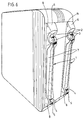
- La figure 6 représente une vue schématique en perspective d'un bagage assemblé avec deux supports selon l'invention.
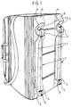
- La figure 7 représente une vue schématique en perspective d'un bagage assemblé avec un support à plaque selon l'invention.
- FIG. 1 represents a schematic side view of a device according to the invention,
- Figure 2 shows a schematic top view of a device according to the invention;
- Figure 3 shows a partial schematic sectional view along line III-III of Figure 2;
- 4 shows a partial schematic view in section along the line IV-IV of Figure 2;
- 5 shows a partial schematic view in section along the line VV of Figure 2;
- FIG. 6 represents a schematic perspective view of a bag assembled with two supports according to the invention.
- FIG. 7 represents a schematic perspective view of a bag assembled with a plate support according to the invention.
En référence à la figure 1, un dispositif selon l'invention comporte un corps 1 de forme allongée conformé en patin de glissement selon le sens longitudinal.Referring to Figure 1, a device according to the invention comprises a
Le corps 1 comporte à sa partie avant (en référence au sens d'utilisation) un logement 2 formant cuvette d'orientation pour une roulette orientable 3. Le corps 1 comporte à sa partie arrière un logement 4 propre à recevoir une roulette 5 d'orientation fixe, et orientée de manière à ce que le roulement s'effectue selon le sens longitudinal du corps 1.The
La roulette 3 orientable est montée sur le corps 1 à l'aide d'une plaque de base 3a par exemple de forme rectangulaire, sur laquelle est monté à pivotement un ensemble porte-axe 3b. Dans cet exemple, l'ensemble porte-axe 3b comporte une plaque circulaire et deux bras latéraux solidaires et sensiblement perpendiculaires à cette plaque de base : les deux bras latéraux supportent la roue 3c.The orientable caster 3 is mounted on the
La roulette 5 d'orientation longitudinale par rapport au corps 1 est montée à rotation directement sur le corps 1 au moyen de son axe 5a.The
Selon l'invention, le corps 1 est conformé en patin de glissement et présente une partie frontale 6 inclinée par rapport au plan de roulement.According to the invention, the
La partie frontale 6 présente une première surface 6a sensiblement plane et inclinée, par exemple d'un angle compris entre 30° et 60° par rapport au plan de roulement.The
La surface 6a se raccorde tangentiellement à une surface 6b de forme généralement convexe. Le plan tangent 6c à l'extrémité de la surface 6b (symbolisé en traits pointillés sur les figures 1 et 3) rencontre la roue 3c sensiblement en dessous du tiers inférieur de la roue 3, lorsque celle-ci est orientée dans le sens d'utilisation normal, c'est-à-dire que la surface d'intersection du plan 6c avec la roue 3c est vue depuis l'axe de rotation sous un angle de l'ordre de ou sensiblement inférieur à 120°.The
La partie centrale 7 du corps 1 présente une forme générale en V et sans angles vifs susceptibles d'accrocher un rebord ou un obstacle quelconque.The
La partie arrière 8 du corps 1 présente une surface sensiblement plane inclinée par rapport au plan de roulement d'un angle compris, par exemple entre 30° et 60° ; le prolongement de cette surface (en traits pointillés) vient rencontrer la roulette d'orientation fixe 5.The
On obtient ainsi un encastrement d'une part de la roulette orientable 3 dans un logement 2 de façon à être protégée contre les chocs par les surfaces 6a, 6b et 11a et d'autre part de la roulette fixe 5 dans un logement 4 de façon à être protégée par les surfaces 11b et 8. Cet encastrement permet un franchissement aisé des obstacles tels que des marches par exemple.One thus obtains an embedding on the one hand of the orientable caster 3 in a
En référence à la figure 2, sur laquelle les chiffres de référence identiques désignent des éléments identiques à ceux de la figure 1, le dispositif selon l'invention s'inscrit dans un contour de forme générale en U, dont les côtés 9, 10 présentent un évasement opposé au plan de roulement.With reference to FIG. 2, in which the identical reference numerals designate elements identical to those of FIG. 1, the device according to the invention is part of a generally U-shaped outline, the
En référence à la figure 3, le logement avant 2 présente un renfoncement 2a ou une forme coopérante analogue pour fixer la plaque de base 3a de la roulette avant 3.With reference to FIG. 3, the
Le logement arrière 4 présente au moins un orifice ou analogue 4a pour le logement d'un axe de rotation 5a d'une roulette 5. De préférence, l'axe 5a est traversant et passe par deux orifices 4a disposés de part et d'autre du logement 4.The
La partie centrale 7 présente un bord inférieur 11 incliné vers le bas d'avant en arrière, de manière à ce que l'avant 11a du bord inférieur 11 se situe sensiblement en dessous du niveau de l'axe de la roue 3c et que l'arrière 11b du bord inférieur 11 se situe légèrement au-dessus du plan de roulement de la roulette 5.The
En référence aux figures 4 et 5, la partie centrale 7 s'inscrit dans le contour général représenté en traits pointillés en forme de U du dispositif.Referring to Figures 4 and 5, the
La partie centrale 7 présente une section s'élargissant d'avant en arrière et qui présente une section en forme de V dont la pointe est constituée par le bord inférieur 11.The
Selon l'invention, le dispositif de support à roulettes présente une forme toujours en contact avec le sol et apte à permettre l'avancement par combinaison de glissement et/ou de roulement en dépit des obstacles de forme diverse rencontrés.According to the invention, the support device on casters has a shape always in contact with the ground and able to allow advancement by combination of sliding and / or rolling despite obstacles of various shape encountered.
La forme générale en U évasé évite l'encastrement dans un rétrécissement ; l'élargissement de la section en forme de V assure la stabilité de la charge supportée ; le pivotement de la roulette avant permet le changement de direction sans effort.The general flared U shape avoids embedding in a narrowing; the widening of the V-shaped section ensures the stability of the supported load; the pivoting of the front caster allows effortless change of direction.
En référence à la figure 6, une valise selon l'invention est munie de deux dispositifs selon l'invention sensiblement parallèles entre eux et aux faces latérales de la valise.Referring to Figure 6, a suitcase according to the invention is provided with two devices according to the invention substantially parallel to each other and to the side faces of the suitcase.
Les roulettes avant 3 des dispositifs selon l'invention sont situées du même côté dans le sens de roulement normal.The front rollers 3 of the devices according to the invention are located on the same side in the normal rolling direction.
Bien entendu, l'invention s'applique également à toute forme de conteneur : malle, caisse, etc... muni d'un nombre quelconque de dispositifs selon l'invention, fixés de façon permanente (par thermosoudage, collage, rivetage ou un procédé analogue) ou amovible (vissage , encliquetage ou un procédé analogue).Of course, the invention also applies to any form of container: trunk, box, etc. provided with any number of devices according to the invention, permanently fixed (by heat sealing, gluing, riveting or a similar process) or removable (screwing, snap-fastening or a similar process).
L'invention s'applique à tous types de bagages que ceux-ci soient rigides ou non.The invention applies to all types of luggage, whether these are rigid or not.
En particulier, dans le cas d'un bagage entièrement souple (en cuir, toile ou analogue), il suffit de raidir le fond du bagage par une plaque en tout matériau rigide approprié sur laquelle seront fixés le ou les patins.In particular, in the case of fully flexible luggage (leather, canvas or the like), it suffices to stiffen the bottom of the luggage by a plate made of any suitable rigid material on which the pad (s) will be fixed.
Selon l'invention, on peut fabriquer le dispositif comme cela est représenté à la figure 7, c'est-à-dire qu'il est constitué de deux patins solidaires d'une plaque rigide de façon à constituer une sorte de planche à roulettes qui peut être fixée au fond de tout bagage souple de façon d'une part, à en rigidifier le fond, et d'autre part, à le doter de roues.According to the invention, the device can be manufactured as shown in Figure 7, that is to say that it consists of two pads integral with a rigid plate so as to constitute a kind of skateboard which can be fixed to the bottom of any flexible luggage so as to, on the one hand, to stiffen the bottom, and on the other hand, to provide it with wheels.
Avantageusement, selon l'invention, le dispositif pourra être monté automatiquement directement en bout de la chaîne de fabrication des valises : il sera alors constitué au moins du côté destiné à être assemblé aux valises avec le même matériau ou un matériau compatible avec celui des valises (notamment une matière thermoplastique telle que du polypropylène).Advantageously, according to the invention, the device can be mounted automatically directly at the end of the chain for manufacturing suitcases: it will then consist at least of the side intended to be assembled to suitcases with the same material or a material compatible with that of the suitcases (in particular a thermoplastic material such as polypropylene).
Avantageusement, le dispositif peut également venir de matière d'une seule pièce (par moulage, thermoformage ou un procédé analogue) avec le bagage, ou avec la plaque rigide dans le cas d'un bagage souple.Advantageously, the device can also come in one piece material (by molding, thermoforming or a similar process) with the luggage, or with the rigid plate in the case of a flexible luggage.
Claims (12)
- A support device with rollers, adaptable to an item of luggage, a suitcase, a trunk or the like, provided with at least one elongate body (1), said body (1) comprising on its rear part a housing (4) into which is placed a roller (5) of fixed orientation, characterised by the fact that said body (1) is formed as a sliding block in which are embedded firstly said housing (4) for said roller (5) and secondly, on its front part, another housing (2) for a steerable roller (3).
- A device according to Claim 1, characterised in that the body (1) has a front part (6) which is inclined relative to the plane of rolling.
- A device according to Claim 2, characterised in that the front part (6) comprises a surface (6b), the plane (6c) of which which is tangent to the end meets the wheel (3c) of the steerable roller (3) substantially below the bottom third, when said roller is directed in the normal direction of use.
- A device according to one of Claims 1 to 3, characterised in that the body (1) has a central part (7) with a lower edge (11) inclined towards the bottom from front to back.
- A device according to Claim 4, characterised in that the central part (7) has a section which widens from front to back.
- A device according to any one of Claims 1 to 5, characterised in that the housings (2, 4) for the rollers (3, 5) are protected by the front and rear inclined planes (6, 8) and the central part (11) which separates them, such that the device has a shape permitting advance despite obstacles by a combination of sliding and/or rolling.
- A device according to any one of Claims 1 to 5, characterised in that the device lies within a contour in the general shape of a widened U, the widening of which is opposed to the plane of travel.
- A device according to Claim 7, characterised in that the body (1) has a V-shaped section lying within the general contour in the shape of a widened U.
- An item of luggage, trunk or the like, comprising at least one device according to any one of Claims 1 to 8.
- An item of luggage according to Claim 9, characterised in that it is a flexible item of luggage, the base of which is stiffened by a rigid plate of any suitable material, to which is attached at least one device according to any one of Claims 1 to 7.
- A flexible item of luggage according to Claim 10, characterised in that the plate is fixed to the device(s), for example by Screwing, locking or a similar method.
- A flexible item of luggage according to Claim 10, characterised in that the plate is made of a material integral with the device(s).
Applications Claiming Priority (2)
| Application Number | Priority Date | Filing Date | Title |
|---|---|---|---|
| FR9206355 | 1992-05-25 | ||
| FR9206355A FR2691338A1 (en) | 1992-05-25 | 1992-05-25 | Support device with wheels and luggage incorporating at least one such device. |
Publications (2)
| Publication Number | Publication Date |
|---|---|
| EP0572297A1 EP0572297A1 (en) | 1993-12-01 |
| EP0572297B1 true EP0572297B1 (en) | 1996-12-11 |
Family
ID=9430133
Family Applications (1)
| Application Number | Title | Priority Date | Filing Date |
|---|---|---|---|
| EP93401240A Expired - Lifetime EP0572297B1 (en) | 1992-05-25 | 1993-05-14 | Support device for rollers and luggage with such a device |
Country Status (7)
| Country | Link |
|---|---|
| US (1) | US5531465A (en) |
| EP (1) | EP0572297B1 (en) |
| JP (1) | JPH06181809A (en) |
| CA (1) | CA2096797A1 (en) |
| DE (1) | DE69306474T2 (en) |
| FR (1) | FR2691338A1 (en) |
| HK (1) | HK1007941A1 (en) |
Families Citing this family (8)
| Publication number | Priority date | Publication date | Assignee | Title |
|---|---|---|---|---|
| FR2729550B1 (en) * | 1995-01-23 | 1997-04-11 | Delsey Soc | ADJUSTABLE DEVICE FOR SUPPORTING CASTERS AND LUGGAGE INCORPORATING AT LEAST ONE SUCH DEVICE |
| US5630521A (en) * | 1996-04-23 | 1997-05-20 | Samsonite Corporation | Ergonomic upright wheeled luggage |
| GB9807169D0 (en) | 1998-04-03 | 1998-06-03 | Astec Europ | Trap for catching insects |
| US6561530B2 (en) | 2001-04-27 | 2003-05-13 | Pull-Buoy, Inc. | Gym scooter |
| US7878514B1 (en) * | 2007-05-04 | 2011-02-01 | Cunningham Hopkins, LLC | Self leveling mop bucket cart |
| CA2730557A1 (en) * | 2008-07-15 | 2010-01-21 | Robert M. Caya | Portable multi-directional exercise apparatus |
| JP5753499B2 (en) * | 2012-01-24 | 2015-07-22 | 株式会社シフレ | suitcase |
| US20150001020A1 (en) * | 2013-06-26 | 2015-01-01 | King Fahd University Of Petroleum And Minerals | Luggage sliders |
Family Cites Families (15)
| Publication number | Priority date | Publication date | Assignee | Title |
|---|---|---|---|---|
| US746816A (en) * | 1902-09-05 | 1903-12-15 | Charles Alcott Goddard | Dry-kiln truck. |
| US765751A (en) * | 1903-12-14 | 1904-07-26 | James I Ott | Bunk or truck for lumber-driers. |
| GB212352A (en) * | 1923-01-08 | 1924-03-13 | William Norman Goldsmith | Means for transporting all forms of hand bags, portmanteaux, kit bags, travelling trunks and the like |
| US2596578A (en) * | 1949-03-05 | 1952-05-13 | Grace H Mcintyre | Wheeled suitcase |
| US2675245A (en) * | 1949-06-13 | 1954-04-13 | Herrmann B Tobias | Baggage trundle |
| FR1197511A (en) * | 1958-07-02 | 1959-12-01 | Mobile stabilizer base for household appliances | |
| US2964329A (en) * | 1958-08-07 | 1960-12-13 | Beck Olga | Self tensioning detachable luggage caster rollers |
| US3057002A (en) * | 1959-08-12 | 1962-10-09 | William G Levin | Combination ball bearing roller and hinge for luggage and the like |
| US3532355A (en) * | 1968-10-22 | 1970-10-06 | Evelyn V Hawkes | Luggage carrier |
| US3580601A (en) * | 1969-04-30 | 1971-05-25 | Ray P Miles | Skate device for transporting large objects |
| US4168558A (en) * | 1978-03-13 | 1979-09-25 | Brooks Walker | Mount for wheeled suitcases |
| WO1985000329A1 (en) * | 1983-07-12 | 1985-01-31 | Baker Franklin W | Portable luggage carrier |
| US4589530A (en) * | 1985-06-26 | 1986-05-20 | Sher Yuh Y | Collapsible wheeled luggage with stiffener |
| US5048649A (en) * | 1990-03-02 | 1991-09-17 | American Tourister, Inc. | Luggage with pull handle |
| US5134753A (en) * | 1991-01-18 | 1992-08-04 | Firma Sudhaus Schloss- Und Beschlagtechnik Gmbh & Co. | Luggage caster |
-
1992
- 1992-05-25 FR FR9206355A patent/FR2691338A1/en active Granted
-
1993
- 1993-05-14 EP EP93401240A patent/EP0572297B1/en not_active Expired - Lifetime
- 1993-05-14 DE DE69306474T patent/DE69306474T2/en not_active Expired - Fee Related
- 1993-05-19 JP JP5139273A patent/JPH06181809A/en active Pending
- 1993-05-21 CA CA002096797A patent/CA2096797A1/en not_active Abandoned
- 1993-05-24 US US08/064,934 patent/US5531465A/en not_active Expired - Fee Related
-
1998
- 1998-06-27 HK HK98107257A patent/HK1007941A1/en not_active IP Right Cessation
Also Published As
| Publication number | Publication date |
|---|---|
| HK1007941A1 (en) | 1999-04-30 |
| JPH06181809A (en) | 1994-07-05 |
| FR2691338B1 (en) | 1994-07-13 |
| FR2691338A1 (en) | 1993-11-26 |
| DE69306474D1 (en) | 1997-01-23 |
| EP0572297A1 (en) | 1993-12-01 |
| US5531465A (en) | 1996-07-02 |
| DE69306474T2 (en) | 1997-05-22 |
| CA2096797A1 (en) | 1993-11-26 |
Similar Documents
| Publication | Publication Date | Title |
|---|---|---|
| EP0340260B1 (en) | Roller skates comprising at least two rollers aligned along a medial plane | |
| FR2692766A1 (en) | Suitcase mounted on wheels. | |
| WO1999043532A1 (en) | Infant's pushchair | |
| FR2672191A1 (en) | Luggage equipped with four rolling elements | |
| FR2522940A1 (en) | TRACTION HANDLE FOR CASE WITH CASTERS | |
| EP0572297B1 (en) | Support device for rollers and luggage with such a device | |
| FR2738209A1 (en) | TROLLEY COMPRISING A FRAME MOUNTED ON PIVOTING WHEEL DEVICES, AND PIVOTING WHEEL DEVICE IN PARTICULAR FOR SUCH A TROLLEY | |
| EP0380597A1 (en) | Braking device for skates and skate boards | |
| FR2974279A1 (en) | LUGGAGE DEVICE COMBINED WITH INDIVIDUAL TRANSPORT MEANS | |
| FR3053302A1 (en) | MOTORIZED HANDLING TROLLEY | |
| WO1993024029A1 (en) | Rigid or soft baggage fitted with wheels and a handle | |
| FR2903364A1 (en) | Roller for object transporting trunk i.e. trolley case, is mounted on rotational axle that is mounted on articulation unit, where unit has pivoting axle housed in wall of adapter case, and is formed of rod pivotably mounted on pivoting axle | |
| FR2577772A1 (en) | CONTAINER SUCH AS SUITCASE | |
| FR2752406A1 (en) | PROVISIONS TROLLEY WITH A SEAT FOR A CHILD OR A BABY | |
| FR2831459A1 (en) | TOY FORMING ROCKER SEAT OR PUSHER ON WHEELS AND METHOD FOR ADAPTING SUCH A TOY | |
| FR2729550A1 (en) | ADJUSTABLE ROLLER AND BAG HOLDER DEVICE INCORPORATING AT LEAST ONE SUCH DEVICE | |
| FR2670125A1 (en) | Transport device in two separate parts, each including only two wheels placed at the outside of a support | |
| EP0838372B1 (en) | Device to help loading a luggage boot of a motor vehicle | |
| EP0814005B1 (en) | Box with chock | |
| FR2915728A1 (en) | Kick scooter for use by skater, has rear wheels mounted pivotingly around axis perpendicular to rotation axis of rear wheels and to advancement direction of scooter, where return units are provided to bring back wheels mounted in position | |
| BE1009456A6 (en) | Hand luggage | |
| FR2652326A1 (en) | Shopping trolley | |
| FR2768113A1 (en) | BRAKE MECHANISM FOR TROLLEY | |
| FR3003180A1 (en) | DEVICE FOR TRANSPORTING LONGILINE ELEMENTS, IN PARTICULAR SKIERS | |
| FR2591872A1 (en) | Strap with castors |
Legal Events
| Date | Code | Title | Description |
|---|---|---|---|
| PUAI | Public reference made under article 153(3) epc to a published international application that has entered the european phase |
Free format text: ORIGINAL CODE: 0009012 |
|
| AK | Designated contracting states |
Kind code of ref document: A1 Designated state(s): BE DE FR GB IT |
|
| 17P | Request for examination filed |
Effective date: 19940418 |
|
| 17Q | First examination report despatched |
Effective date: 19950322 |
|
| GRAG | Despatch of communication of intention to grant |
Free format text: ORIGINAL CODE: EPIDOS AGRA |
|
| GRAH | Despatch of communication of intention to grant a patent |
Free format text: ORIGINAL CODE: EPIDOS IGRA |
|
| GRAH | Despatch of communication of intention to grant a patent |
Free format text: ORIGINAL CODE: EPIDOS IGRA |
|
| GRAA | (expected) grant |
Free format text: ORIGINAL CODE: 0009210 |
|
| AK | Designated contracting states |
Kind code of ref document: B1 Designated state(s): BE DE FR GB IT |
|
| RAP2 | Party data changed (patent owner data changed or rights of a patent transferred) |
Owner name: DELSEY |
|
| REF | Corresponds to: |
Ref document number: 69306474 Country of ref document: DE Date of ref document: 19970123 |
|
| ITF | It: translation for a ep patent filed |
Owner name: SAIC BREVETTI S.R.L. |
|
| GBT | Gb: translation of ep patent filed (gb section 77(6)(a)/1977) |
Effective date: 19970226 |
|
| PLBE | No opposition filed within time limit |
Free format text: ORIGINAL CODE: 0009261 |
|
| STAA | Information on the status of an ep patent application or granted ep patent |
Free format text: STATUS: NO OPPOSITION FILED WITHIN TIME LIMIT |
|
| 26N | No opposition filed | ||
| PGFP | Annual fee paid to national office [announced via postgrant information from national office to epo] |
Ref country code: DE Payment date: 20010412 Year of fee payment: 9 |
|
| PGFP | Annual fee paid to national office [announced via postgrant information from national office to epo] |
Ref country code: BE Payment date: 20010418 Year of fee payment: 9 |
|
| PGFP | Annual fee paid to national office [announced via postgrant information from national office to epo] |
Ref country code: FR Payment date: 20010430 Year of fee payment: 9 |
|
| PGFP | Annual fee paid to national office [announced via postgrant information from national office to epo] |
Ref country code: GB Payment date: 20010509 Year of fee payment: 9 |
|
| REG | Reference to a national code |
Ref country code: GB Ref legal event code: IF02 |
|
| PG25 | Lapsed in a contracting state [announced via postgrant information from national office to epo] |
Ref country code: GB Free format text: LAPSE BECAUSE OF NON-PAYMENT OF DUE FEES Effective date: 20020514 |
|
| PG25 | Lapsed in a contracting state [announced via postgrant information from national office to epo] |
Ref country code: BE Free format text: LAPSE BECAUSE OF NON-PAYMENT OF DUE FEES Effective date: 20020531 |
|
| PG25 | Lapsed in a contracting state [announced via postgrant information from national office to epo] |
Ref country code: DE Free format text: LAPSE BECAUSE OF NON-PAYMENT OF DUE FEES Effective date: 20021203 |
|
| GBPC | Gb: european patent ceased through non-payment of renewal fee |
Effective date: 20020514 |
|
| PG25 | Lapsed in a contracting state [announced via postgrant information from national office to epo] |
Ref country code: FR Free format text: LAPSE BECAUSE OF NON-PAYMENT OF DUE FEES Effective date: 20030131 |
|
| REG | Reference to a national code |
Ref country code: FR Ref legal event code: ST |
|
| PG25 | Lapsed in a contracting state [announced via postgrant information from national office to epo] |
Ref country code: IT Free format text: LAPSE BECAUSE OF NON-PAYMENT OF DUE FEES Effective date: 20050514 |