EP0572011B1 - Radiator assembly for substrate - Google Patents
Radiator assembly for substrate Download PDFInfo
- Publication number
- EP0572011B1 EP0572011B1 EP93108596A EP93108596A EP0572011B1 EP 0572011 B1 EP0572011 B1 EP 0572011B1 EP 93108596 A EP93108596 A EP 93108596A EP 93108596 A EP93108596 A EP 93108596A EP 0572011 B1 EP0572011 B1 EP 0572011B1
- Authority
- EP
- European Patent Office
- Prior art keywords
- radiator
- substrate
- fitting plate
- assembly
- fixed
- Prior art date
- Legal status (The legal status is an assumption and is not a legal conclusion. Google has not performed a legal analysis and makes no representation as to the accuracy of the status listed.)
- Expired - Lifetime
Links
Images


Classifications
-
- H—ELECTRICITY
- H01—ELECTRIC ELEMENTS
- H01L—SEMICONDUCTOR DEVICES NOT COVERED BY CLASS H10
- H01L23/00—Details of semiconductor or other solid state devices
- H01L23/34—Arrangements for cooling, heating, ventilating or temperature compensation ; Temperature sensing arrangements
- H01L23/40—Mountings or securing means for detachable cooling or heating arrangements ; fixed by friction, plugs or springs
- H01L23/4006—Mountings or securing means for detachable cooling or heating arrangements ; fixed by friction, plugs or springs with bolts or screws
- H01L2023/4037—Mountings or securing means for detachable cooling or heating arrangements ; fixed by friction, plugs or springs with bolts or screws characterised by thermal path or place of attachment of heatsink
- H01L2023/405—Mountings or securing means for detachable cooling or heating arrangements ; fixed by friction, plugs or springs with bolts or screws characterised by thermal path or place of attachment of heatsink heatsink to package
-
- H—ELECTRICITY
- H01—ELECTRIC ELEMENTS
- H01L—SEMICONDUCTOR DEVICES NOT COVERED BY CLASS H10
- H01L23/00—Details of semiconductor or other solid state devices
- H01L23/34—Arrangements for cooling, heating, ventilating or temperature compensation ; Temperature sensing arrangements
- H01L23/40—Mountings or securing means for detachable cooling or heating arrangements ; fixed by friction, plugs or springs
- H01L23/4006—Mountings or securing means for detachable cooling or heating arrangements ; fixed by friction, plugs or springs with bolts or screws
- H01L2023/4037—Mountings or securing means for detachable cooling or heating arrangements ; fixed by friction, plugs or springs with bolts or screws characterised by thermal path or place of attachment of heatsink
- H01L2023/4062—Mountings or securing means for detachable cooling or heating arrangements ; fixed by friction, plugs or springs with bolts or screws characterised by thermal path or place of attachment of heatsink heatsink to or through board or cabinet
-
- H—ELECTRICITY
- H01—ELECTRIC ELEMENTS
- H01L—SEMICONDUCTOR DEVICES NOT COVERED BY CLASS H10
- H01L23/00—Details of semiconductor or other solid state devices
- H01L23/34—Arrangements for cooling, heating, ventilating or temperature compensation ; Temperature sensing arrangements
- H01L23/40—Mountings or securing means for detachable cooling or heating arrangements ; fixed by friction, plugs or springs
- H01L23/4006—Mountings or securing means for detachable cooling or heating arrangements ; fixed by friction, plugs or springs with bolts or screws
- H01L2023/4075—Mechanical elements
- H01L2023/4087—Mounting accessories, interposers, clamping or screwing parts
-
- H—ELECTRICITY
- H01—ELECTRIC ELEMENTS
- H01L—SEMICONDUCTOR DEVICES NOT COVERED BY CLASS H10
- H01L2924/00—Indexing scheme for arrangements or methods for connecting or disconnecting semiconductor or solid-state bodies as covered by H01L24/00
- H01L2924/0001—Technical content checked by a classifier
- H01L2924/0002—Not covered by any one of groups H01L24/00, H01L24/00 and H01L2224/00
Definitions
- the present invention relates to a radiator assembly fixed to a substrate via soldered metal plate, and particularly it relates to a radiator which can be separated or disassembled from a substrate by using a typical common tool in order to be used as recycling resources after retirement of the assembly including the radiator.
- an aluminum radiator which is manufactured by an extrusion molding, is widely used in an electronic apparatus, which comprises a substrate having many electronic devices mounted at high density.
- the radiator is usually made of aluminum block since it can be manufactured by easy treatment and have excellent heat-conductivity.
- Such aluminum radiators prevent the appearance of malfunction or destruction caused by heat of an electronic device, such as a semiconductor device. And the semiconductor device attached to such aluminum radiator is operated in excellent performance.
- FIG.5 is a perspective view of the conventional aluminum radiator 30 mounted on a substrate 80.
- a semiconductor device 10 to be cooled is fixed to the conventional aluminum radiator 30 through an insulation sheet 20 such as a mica sheet by tightening a screw 40.
- the aluminum radiator 30 can not be fixed directly to the substrate 80 by soldering, the aluminum radiator 30 is fixed to metal plates 50 by caulked joints 30a, and the metal plates 50 formed in a flat plate are fixed to the substrate 80 by soldering.
- the conventional aluminum radiator 30 is firmly fixed to the substrate 80 usually.
- the conventional radiator 30 of the electronic device can not be easily separated from the substrate 80 by a typical or ordinary tool, and semiconductor device only can be separated from the conventional radiator 30 by removing the screw 40 with a screwdriver tool. As a result, the substrate 80 having the conventional radiator 30 must be scrapped with the other electronics in spite of the usable material as recycling resources.
- An object of the present invention is to provide a radiator assembly which can be easily separated from a substrate of an electronic apparatus in order to be used as recycling resources in a manner of a typical tool when the electronic apparatus is retired.
- the radiator assembly for a substrate comprises: a substrate for mounting an electronic device; a fitting plate fixed to the substrate by at least a welding joint; and a radiator for cooling an electronic device which is heat-conductively attached to the radiator which is coupled to the fitting plate by mechanical connecting means, the radiator having at least a hollow forming at least an aperture for receiving a pry tool between the fitting plate and the radiator.
- another radiator assembly in accordance with the present invention comprises: a substrate for mounting an electronic device; a radiator for cooling the electronic device which is heat-conductively attached to the radiator; and a fitting plate which is fixed to the substrate by at least a welding joint, the fitting plate being coupled to the radiator by mechanical connecting means, the fitting plate having swelled portions forming apertures for receiving a pry tool between the fitting plate and the radiator.
- the radiator assembly in accordance with the present invention which is configured above, is constructed to have apertures between the radiator and the fitting plate so as to be inserted a typical tool for separating between the radiator and the fitting plate.
- a typical tool such as screwdriver
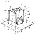
- FIG.1 is a perspective view showing a radiator assembly of a first embodiment of the present invention.
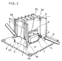
- FIG.2 is a perspective view showing the radiator assembly of FIG.1 on a way of a disassembly.
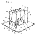
- FIG.3 is a perspective view showing a radiator assembly of a second embodiment of the present invention.
- FIG.4 is a perspective view showing the radiator assembly of FIG.3 on a way of a disassembly.
- FIG.5 is the perspective view showing the conventional radiator mounted on the substrate.
- radiator assemblies to be mounted on a substrate as preferred embodiments of the present invention are described with reference to the accompanying drawings of FIGs.1 to 4.
- FIG.1 is a perspective view showing a radiator assembly of the first embodiment embodying the present invention.
- FIG.2 is a perspective view showing the radiator assembly of FIG.1 on a way of a disassembly.
- a semiconductor device 1 is thermo-conductively attached to a radiator 3 with an insulation sheet 2 such as a mica sheet by tightening a screw 4 inbetween.
- the radiator 3 having plural cooling fins is manufactured by an extrusion molding of aluminum.
- Two metallic fitting plates 5, 5 are attached to the radiator 3 at both side faces.
- the fitting plate 5 is slid and fitted into each-other-opposing two grooves 3a, 3a, which are formed on vertical edge portions of side wall 3d of the radiator 3 as shown in FIG.1.
- the fitting plate 5 is firmly fixed at the predetermined position of the side wall 3d by caulking at plural portions 3b, 3b, 3b, 3b of guide rails of the grooves 3a, 3a.
- the side wall 3d is formed to have two belt-shaped hollows 3c, 3c, namely two substantially vertical straight grooves.
- Two apertures 7, 7 are formed by attaching the fitting plates 5 to the side wall 3d of the radiator 3, because the side wall 3d has the belt-shaped hollows 3c, 3c.
- the apertures 7 are arranged to be close to the caulked joints 3b connecting between the fitting plate 5 and the side wall 3d of the radiator 3.
- the aperture 7 have a grooved shape to be easily inserted by a typical tool, such as a slotted screwdriver 6.
- the radiator 3 is firmly fixed to the substrate 8 in a manner that the fitting plates 5 are fixed to the substrate 8 by soldering.
- the semiconductor device 1 is initially separated from the radiator 3 by removing the screw 4 with a typical tool, such as a Philip screwdriver 9 as shown in FIG.2.
- the slotted screwdriver 6 is also inserted and the other aperture 7 is pried open, thereby removing the fitting plate 5 from the side wall 3d of the radiator 3. As a result, the radiator 3 is separated from one fitting plate 5.
- FIG.3 is a perspective view showing a radiator assembly of the second embodiment embodying the present invention.
- FIG.4 is a perspective view showing the radiator assembly of FIG.3 on a way of a disassembly.
- Corresponding parts and components to the first embodiment are shown by the same numerals and marks, and the description thereon made in the first embodiment similarly apply. Differences and features of this second embodiment from the first embodiment are as follows.
- a semiconductor device 1 is thermo-conductively attached to a radiator 3 with an insulation sheet 2, such as a mica sheet, by tightening a screw 4 inbetween.
- the radiator 3 having plural cooling fins is manufactured by an extrusion molding of aluminum.
- Two metallic fitting plates 15, 15 are attached to the radiator 3 at both side faces.
- the fitting plate 15 is slid and fitted into each-other-opposing two grooves 3a, 3a, which are formed vertical on edge portions of side wall 3d of the radiator 3 as shown in FIG.3.
- the fitting plate 15 is firmly fixed at the predetermined position of the side wall 3d by caulking at plural portions 3b, 3b, 3b, 3b of guide rails of the grooves 3a, 3a.
- the fitting plate 15 is formed to have two swelled portions 15a, 15a like two pockets.
- Two apertures 7, 7 are formed by attaching the fitting plate 15 to the side wall 3d of the radiator 3 because the fitting plate 15 has the swelled portions 15a.
- the apertures 7 are arranged close to the caulked joints 3b connecting between the fitting plate 15 and the side wall 3d of the radiator 3.
- the aperture 7 have a slotted shape so as to easily receive a typical tool, such as a slotted screwdriver 6.
- the radiator 3 is firmly fixed to the substrate 8 in a manner that the fitting plates 15 are fixed to the substrate 8 by soldering.
- the semiconductor device 1 is initially separated from the radiator 3 by removing the screw 4 with a typical tool, such as a Philip screwdriver 9 as shown in FIG.4.
- a slotted screwdriver 6 is inserted into the aperture 7, which is formed by attaching the fitting plate 15 having swelled portions 15a to the side wall 3d. And, the fitting plate 15 is pried from the side wall 3d by pushing the slotted screwdriver 6 in the aperture 7 so as to break the caulked joints 3b as shown in FIG.4.
- the slotted screwdriver 6 is also inserted and the other aperture 7 is pried open, thereby removing the fitting plate 15 from the side wall 3d of the radiator 3. As a result, the radiator 3 is separated from one fitting plate 15.
- a modified embodiment may be such that the radiator and the fitting plate are coupled by optional mechanical coupling means, such as pressure welding, rivet joint.
Description
- The present invention relates to a radiator assembly fixed to a substrate via soldered metal plate, and particularly it relates to a radiator which can be separated or disassembled from a substrate by using a typical common tool in order to be used as recycling resources after retirement of the assembly including the radiator.
- Recently, an aluminum radiator, which is manufactured by an extrusion molding, is widely used in an electronic apparatus, which comprises a substrate having many electronic devices mounted at high density. The radiator is usually made of aluminum block since it can be manufactured by easy treatment and have excellent heat-conductivity. Such aluminum radiators prevent the appearance of malfunction or destruction caused by heat of an electronic device, such as a semiconductor device. And the semiconductor device attached to such aluminum radiator is operated in excellent performance.
- In view of an environmental disruption of the globe and the recycling of resources, disassembly and classification of the electronic apparatus to be scrapped have lately been attracting considerable attention. It becomes one of the most importance matter in an electronic apparatus in recent years that many kinds of electronic devices in electronic apparatus are assembled so as to be easily disassembled and classified into same material in order to recycle the resources. Particularly, since the large block of aluminum wares were made by consuming a great amount of electricity in smelting, the aluminum ware is preferably used as recycling.
- Next, a way of disassembly for such aluminum ware, especially a conventional aluminum radiator, is described with reference to FIG 5. FIG.5 is a perspective view of the
conventional aluminum radiator 30 mounted on asubstrate 80. As shown in FIG.5, asemiconductor device 10 to be cooled is fixed to theconventional aluminum radiator 30 through aninsulation sheet 20 such as a mica sheet by tightening ascrew 40. Since thealuminum radiator 30 can not be fixed directly to thesubstrate 80 by soldering, thealuminum radiator 30 is fixed tometal plates 50 bycaulked joints 30a, and themetal plates 50 formed in a flat plate are fixed to thesubstrate 80 by soldering. By the above-mentioned way, theconventional aluminum radiator 30 is firmly fixed to thesubstrate 80 usually. - Therefore, in case that the electronic apparatus is retired, it is desirable that many kinds of the electronic devices in the electronic apparatus are disassembled and classified in the same material. However, the
conventional radiator 30 of the electronic device can not be easily separated from thesubstrate 80 by a typical or ordinary tool, and semiconductor device only can be separated from theconventional radiator 30 by removing thescrew 40 with a screwdriver tool. As a result, thesubstrate 80 having theconventional radiator 30 must be scrapped with the other electronics in spite of the usable material as recycling resources. - An object of the present invention is to provide a radiator assembly which can be easily separated from a substrate of an electronic apparatus in order to be used as recycling resources in a manner of a typical tool when the electronic apparatus is retired.
- In order to achieve the above-mentioned object, the radiator assembly for a substrate comprises:
a substrate for mounting an electronic device;
a fitting plate fixed to the substrate by at least a welding joint; and
a radiator for cooling an electronic device which is heat-conductively attached to the radiator which is coupled to the fitting plate by mechanical connecting means, the radiator having at least a hollow forming at least an aperture for receiving a pry tool between the fitting plate and the radiator. - And, another radiator assembly in accordance with the present invention comprises:
a substrate for mounting an electronic device;
a radiator for cooling the electronic device which is heat-conductively attached to the radiator; and
a fitting plate which is fixed to the substrate by at least a welding joint, the fitting plate being coupled to the radiator by mechanical connecting means, the fitting plate having swelled portions forming apertures for receiving a pry tool between the fitting plate and the radiator. - In the radiator assembly in accordance with the present invention which is configured above, the radiator assembly is constructed to have apertures between the radiator and the fitting plate so as to be inserted a typical tool for separating between the radiator and the fitting plate. When an electronic device, such as a semiconductor device fitted to the radiator assembly is retired, a radiator of the radiator assembly can be easily separated from the fitting plate fixed to the substrate in a manner that the apertures are pried open with a typical tool, such as screwdriver thereby the separated radiator can be used as recycling resources.
- While the novel features of the invention are set forth particularly in the appended claims, the invention, both as to organization and content, will be better understood and appreciated, along with other objects and features thereof, from the following detailed description taken in conjunction with the drawings.
- FIG.1 is a perspective view showing a radiator assembly of a first embodiment of the present invention.
- FIG.2 is a perspective view showing the radiator assembly of FIG.1 on a way of a disassembly.
- FIG.3 is a perspective view showing a radiator assembly of a second embodiment of the present invention.
- FIG.4 is a perspective view showing the radiator assembly of FIG.3 on a way of a disassembly.
- FIG.5 is the perspective view showing the conventional radiator mounted on the substrate.
- It will be recognized that some or all the Figures are schematic representations for purposes of illustration and do not necessarily depict the actual relative sizes or locations of the elements shown.
- Hereafter, radiator assemblies to be mounted on a substrate as preferred embodiments of the present invention are described with reference to the accompanying drawings of FIGs.1 to 4.
- FIG.1 is a perspective view showing a radiator assembly of the first embodiment embodying the present invention. FIG.2 is a perspective view showing the radiator assembly of FIG.1 on a way of a disassembly.
- In FIG.1, a
semiconductor device 1 is thermo-conductively attached to aradiator 3 with aninsulation sheet 2 such as a mica sheet by tightening ascrew 4 inbetween. Theradiator 3 having plural cooling fins is manufactured by an extrusion molding of aluminum. Twometallic fitting plates radiator 3 at both side faces. Thefitting plate 5 is slid and fitted into each-other-opposing twogrooves side wall 3d of theradiator 3 as shown in FIG.1. Thefitting plate 5 is firmly fixed at the predetermined position of theside wall 3d by caulking atplural portions grooves side wall 3d is formed to have two belt-shaped hollows apertures fitting plates 5 to theside wall 3d of theradiator 3, because theside wall 3d has the belt-shapedhollows apertures 7 are arranged to be close to thecaulked joints 3b connecting between thefitting plate 5 and theside wall 3d of theradiator 3. Theaperture 7 have a grooved shape to be easily inserted by a typical tool, such as a slottedscrewdriver 6. Theradiator 3 is firmly fixed to thesubstrate 8 in a manner that thefitting plates 5 are fixed to thesubstrate 8 by soldering. - Next, with reference to FIGs.1 and 2 description is made on a way of separating or disassembling the above-mentioned radiator assembly, which has been fixed to the
substrate 8 through thefitting plates 5 by caulking and soldering. - In case the
radiator 3 fixed to thesubstrate 8 as shown in FIG.1 is separated from thesubstrate 8, thesemiconductor device 1 is initially separated from theradiator 3 by removing thescrew 4 with a typical tool, such as a Philipscrewdriver 9 as shown in FIG.2. - In the next step, the
aperture 7, which is formed by attaching thefitting plate 5 to theside wall 3d having the belt-shapedhollows 3c, is inserted by a slottedscrewdriver 6. And, thefitting plate 5 is pried from theside wall 3d by pushing in the slottedscrewdriver 6 in theaperture 7 thereby removing the caulked edge part of thefitting plate 5 from thecaulked joints 3b as shown in FIG.2. - Then, into the
other aperture 7, which is arranged on thesame side wall 3d (right side aperture in FIG.2), the slottedscrewdriver 6 is also inserted and theother aperture 7 is pried open, thereby removing thefitting plate 5 from theside wall 3d of theradiator 3. As a result, theradiator 3 is separated from onefitting plate 5. - Separation of the
radiator 3 from the other fitting plate 5 (which is hidden behind theradiator 3 in FIG.2) is carried out in the same way as the above-mentioned separating. Consequently, thealuminum radiator 3 is entirely removed from thesubstrate 8 for use as recycling resources. - Hereafter, a second embodiment of a radiator assembly for a substrate in accordance with the present invention is described concerning the accompanying drawings of FIGs.3 and 4. FIG.3 is a perspective view showing a radiator assembly of the second embodiment embodying the present invention. FIG.4 is a perspective view showing the radiator assembly of FIG.3 on a way of a disassembly. Corresponding parts and components to the first embodiment are shown by the same numerals and marks, and the description thereon made in the first embodiment similarly apply. Differences and features of this second embodiment from the first embodiment are as follows.
- In FIG.3, a
semiconductor device 1 is thermo-conductively attached to aradiator 3 with aninsulation sheet 2, such as a mica sheet, by tightening ascrew 4 inbetween. Theradiator 3 having plural cooling fins is manufactured by an extrusion molding of aluminum. Two metallicfitting plates radiator 3 at both side faces. Thefitting plate 15 is slid and fitted into each-other-opposing twogrooves side wall 3d of theradiator 3 as shown in FIG.3. Thefitting plate 15 is firmly fixed at the predetermined position of theside wall 3d by caulking atplural portions grooves fitting plate 15 is formed to have two swelledportions apertures fitting plate 15 to theside wall 3d of theradiator 3 because thefitting plate 15 has the swelledportions 15a. Theapertures 7 are arranged close to the caulkedjoints 3b connecting between thefitting plate 15 and theside wall 3d of theradiator 3. Theaperture 7 have a slotted shape so as to easily receive a typical tool, such as a slottedscrewdriver 6. Theradiator 3 is firmly fixed to thesubstrate 8 in a manner that thefitting plates 15 are fixed to thesubstrate 8 by soldering. - Next, with reference to FIGs.3 and 4 description is made on a way of separating or disassembling the above-mentioned radiator assembly from the
substrate 8. - In case the
radiator 3 fixed to thesubstrate 8 as shown in FIG.3 is separated from thesubstrate 8, thesemiconductor device 1 is initially separated from theradiator 3 by removing thescrew 4 with a typical tool, such as aPhilip screwdriver 9 as shown in FIG.4. - In the next step, a slotted
screwdriver 6 is inserted into theaperture 7, which is formed by attaching thefitting plate 15 having swelledportions 15a to theside wall 3d. And, thefitting plate 15 is pried from theside wall 3d by pushing the slottedscrewdriver 6 in theaperture 7 so as to break the caulkedjoints 3b as shown in FIG.4. - Then, into the
other aperture 7, which is arranged on thesame side wall 3d (right side aperture in FIG.4), the slottedscrewdriver 6 is also inserted and theother aperture 7 is pried open, thereby removing thefitting plate 15 from theside wall 3d of theradiator 3. As a result, theradiator 3 is separated from one fittingplate 15. - Separation of the
radiator 3 from the other fitting plate 15 ( which is hidden behind theradiator 3 in FIG.4 ) is carried out in the same way as the above-mentioned separating. Consequently, thealuminum radiator 3 is entirely removed from thesubstrate 8 for use as recycling resources. - Apart from the above-mentioned embodiments wherein the
radiator 3 and thefitting plate
Claims (4)
- A radiator assembly for substrate with printed circuit comprising:
a substrate (8) for mounting an electronic device;
a fitting plate (5) fixed to said substrate (8) by at least a welding joint; and
a radiator (3) for cooling an electronic device which is heat-conductively attached to said radiator (3) which is coupled to said fitting plate (5) by mechanical connecting means, said radiator (3) having at least a hollow (3c) forming at least an aperture (7) for receiving a pry tool (6) between said fitting plate (5) and said radiator (3). - An assembly in accordance with claim 1 wherein,
said radiator (3) is coupled to said fitting plate (5) by caulked joints, and said fitting plate (5) is fixed to said substrate (8) by soldering. - A radiator assembly for a substrate comprising:
a substrate (8) for mounting an electronic device;
a radiator (3) for cooling said electronic device which is heat-conductively attached to said radiator (3); and
a fitting plate (15) which is fixed to said substrate (8) by at least a welding joint, said fitting plate being coupled to said radiator (3) by mechanical connecting means, said fitting plate (15) having swelled portions (15a) forming apertures (7) for receiving a pry tool (6) between said fitting plate (50) and said radiator (3). - An assembly in accordance with claim 3 wherein,
said radiator (3) is coupled to said fitting plate (15) by caulked joints, and said fitting plate (15) is fixed to said substrate (8) by soldering.
Applications Claiming Priority (4)
| Application Number | Priority Date | Filing Date | Title |
|---|---|---|---|
| JP36348/92 | 1992-05-29 | ||
| JP3634892U JP2570629Y2 (en) | 1992-05-29 | 1992-05-29 | Heat sink |
| JP3634992U JP2570630Y2 (en) | 1992-05-29 | 1992-05-29 | Heat sink |
| JP36349/92 | 1992-05-29 |
Publications (2)
| Publication Number | Publication Date |
|---|---|
| EP0572011A1 EP0572011A1 (en) | 1993-12-01 |
| EP0572011B1 true EP0572011B1 (en) | 1995-10-25 |
Family
ID=26375392
Family Applications (1)
| Application Number | Title | Priority Date | Filing Date |
|---|---|---|---|
| EP93108596A Expired - Lifetime EP0572011B1 (en) | 1992-05-29 | 1993-05-27 | Radiator assembly for substrate |
Country Status (6)
| Country | Link |
|---|---|
| US (1) | US5372186A (en) |
| EP (1) | EP0572011B1 (en) |
| KR (1) | KR970005003B1 (en) |
| CN (1) | CN1028195C (en) |
| CA (1) | CA2096983C (en) |
| DE (1) | DE69300698T2 (en) |
Families Citing this family (10)
| Publication number | Priority date | Publication date | Assignee | Title |
|---|---|---|---|---|
| US6075703A (en) * | 1997-03-26 | 2000-06-13 | Samsung Electronics Co., Ltd. | Heat sink assembly |
| US6068051A (en) * | 1998-03-23 | 2000-05-30 | Intel Corporation | Channeled heat sink |
| EP1374654A4 (en) * | 2001-03-16 | 2004-10-20 | Aavid Thermalloy Llc | Heat sink |
| DE60320613T2 (en) * | 2002-03-29 | 2009-06-10 | Panasonic Corp., Kadoma | Optical device and its manufacturing method, optical module, and optical transmission system |
| US20050259400A1 (en) * | 2004-05-24 | 2005-11-24 | Formosa Microsemi Co., Ltd. | Heat sinking structure of power semiconductor |
| KR100646404B1 (en) * | 2005-10-26 | 2006-11-14 | 주식회사 만도 | Electronic control unit and electric power steering apparatus including same |
| CN101420841B (en) * | 2008-10-23 | 2012-06-27 | 旭丽电子(广州)有限公司 | Heat radiating mechanism |
| CN103712171B (en) * | 2012-09-28 | 2018-04-20 | 海洋王(东莞)照明科技有限公司 | Rectifier bracket and lighting apparatus |
| CN103429052A (en) * | 2013-07-24 | 2013-12-04 | 昆山维金五金制品有限公司 | Cooling member |
| JP3213011U (en) * | 2017-08-01 | 2017-10-12 | 誠 韓 | Byo and removal tool |
Family Cites Families (9)
| Publication number | Priority date | Publication date | Assignee | Title |
|---|---|---|---|---|
| GB2052164B (en) * | 1979-06-30 | 1983-12-07 | Burroughs Corp | Assemblies of electrical components |
| US4444994A (en) * | 1982-01-29 | 1984-04-24 | Varo, Inc. | Electrically insulated quick disconnect heat sink |
| JPS5972744A (en) * | 1982-10-19 | 1984-04-24 | Nec Corp | Semiconductor device |
| JPS59158389U (en) * | 1983-04-08 | 1984-10-24 | 三菱電機株式会社 | Control device |
| DE3335332A1 (en) * | 1983-09-29 | 1985-04-11 | Siemens AG, 1000 Berlin und 8000 München | DEVICE FOR FASTENING A REFRIGERATOR BODY ON THE COOLING SURFACE OF AN INTEGRATED BLOCK |
| JPS6263946A (en) * | 1985-09-17 | 1987-03-20 | Sharp Corp | Averaging mechanism for wear of photosensitive body |
| JPS6291495A (en) * | 1985-10-15 | 1987-04-25 | Nec Corp | Vapor growth method for thin semiconductor film |
| US4710852A (en) * | 1986-09-26 | 1987-12-01 | General Motors Corporation | Spring retainer for encapsulated semiconductor device |
| GB8700843D0 (en) * | 1987-01-15 | 1987-02-18 | Marston Palmer Ltd | Heat sink |
-
1993
- 1993-05-26 CA CA002096983A patent/CA2096983C/en not_active Expired - Fee Related
- 1993-05-27 KR KR1019930009266A patent/KR970005003B1/en not_active IP Right Cessation
- 1993-05-27 US US08/067,837 patent/US5372186A/en not_active Expired - Fee Related
- 1993-05-27 EP EP93108596A patent/EP0572011B1/en not_active Expired - Lifetime
- 1993-05-27 DE DE69300698T patent/DE69300698T2/en not_active Expired - Fee Related
- 1993-05-28 CN CN93106767A patent/CN1028195C/en not_active Expired - Fee Related
Also Published As
| Publication number | Publication date |
|---|---|
| CN1083305A (en) | 1994-03-02 |
| DE69300698T2 (en) | 1996-06-05 |
| KR970005003B1 (en) | 1997-04-10 |
| KR940006438A (en) | 1994-03-23 |
| CN1028195C (en) | 1995-04-12 |
| DE69300698D1 (en) | 1995-11-30 |
| EP0572011A1 (en) | 1993-12-01 |
| US5372186A (en) | 1994-12-13 |
| CA2096983C (en) | 1996-08-13 |
| CA2096983A1 (en) | 1993-11-30 |
Similar Documents
| Publication | Publication Date | Title |
|---|---|---|
| US7457122B2 (en) | Memory module assembly including a clip for mounting a heat sink thereon | |
| US7443679B2 (en) | Heat dissipating device having a fin also functioning as a fan holder | |
| EP0572011B1 (en) | Radiator assembly for substrate | |
| US6374912B1 (en) | Deep drawn enclosure with integrated heatsink and fastening details | |
| US7151669B2 (en) | Configurable heat sink with matrix clipping system | |
| US20060181852A1 (en) | Heat sink module for an electronic device | |
| CN1380954A (en) | Tamper-proof ballast enclosure | |
| US7697294B2 (en) | Heat dissipation device having an improved fin structure | |
| US7530388B2 (en) | Heat sink | |
| US7646360B2 (en) | Plasma display apparatus and method of manufacturing chassis base used therefor | |
| US6158266A (en) | Process for manufacturing a mounting plate | |
| EP0917418B1 (en) | Electronic apparatus | |
| US20050000682A1 (en) | Heat dissipating fins of heat sink and manufacturing method thereof | |
| US6181561B1 (en) | Heat sink having standoff buttons and a method of manufacturing therefor | |
| EP0932330A1 (en) | Electronic apparatus | |
| US20130186599A1 (en) | Heat dissipating device and method of manufacturing the same | |
| GB2430310A (en) | A heat dissipation device | |
| US6580612B2 (en) | Electric circuit | |
| GB2300974A (en) | Heatsinks having fin members joined to a base | |
| JP2570629Y2 (en) | Heat sink | |
| US6865074B2 (en) | Method of producing electronic unit of radio system and electronic unit | |
| EP0682223B1 (en) | Heat sink with a heat plate | |
| CN110733644B (en) | Reinforced board card support | |
| US5726857A (en) | Apparatus and method for mounting edge connectors within a circuit module | |
| JP2570630Y2 (en) | Heat sink |
Legal Events
| Date | Code | Title | Description |
|---|---|---|---|
| PUAI | Public reference made under article 153(3) epc to a published international application that has entered the european phase |
Free format text: ORIGINAL CODE: 0009012 |
|
| 17P | Request for examination filed |
Effective date: 19930527 |
|
| AK | Designated contracting states |
Kind code of ref document: A1 Designated state(s): DE GB |
|
| 17Q | First examination report despatched |
Effective date: 19941230 |
|
| GRAA | (expected) grant |
Free format text: ORIGINAL CODE: 0009210 |
|
| AK | Designated contracting states |
Kind code of ref document: B1 Designated state(s): DE GB |
|
| REF | Corresponds to: |
Ref document number: 69300698 Country of ref document: DE Date of ref document: 19951130 |
|
| PLBE | No opposition filed within time limit |
Free format text: ORIGINAL CODE: 0009261 |
|
| STAA | Information on the status of an ep patent application or granted ep patent |
Free format text: STATUS: NO OPPOSITION FILED WITHIN TIME LIMIT |
|
| 26N | No opposition filed | ||
| PGFP | Annual fee paid to national office [announced via postgrant information from national office to epo] |
Ref country code: DE Payment date: 20010522 Year of fee payment: 9 |
|
| PGFP | Annual fee paid to national office [announced via postgrant information from national office to epo] |
Ref country code: GB Payment date: 20010523 Year of fee payment: 9 |
|
| REG | Reference to a national code |
Ref country code: GB Ref legal event code: IF02 |
|
| PG25 | Lapsed in a contracting state [announced via postgrant information from national office to epo] |
Ref country code: GB Free format text: LAPSE BECAUSE OF NON-PAYMENT OF DUE FEES Effective date: 20020527 |
|
| PG25 | Lapsed in a contracting state [announced via postgrant information from national office to epo] |
Ref country code: DE Free format text: LAPSE BECAUSE OF NON-PAYMENT OF DUE FEES Effective date: 20021203 |
|
| GBPC | Gb: european patent ceased through non-payment of renewal fee |
Effective date: 20020527 |