EP0570481B1 - Am-fm combined stereo receiver - Google Patents
Am-fm combined stereo receiver Download PDFInfo
- Publication number
- EP0570481B1 EP0570481B1 EP92905676A EP92905676A EP0570481B1 EP 0570481 B1 EP0570481 B1 EP 0570481B1 EP 92905676 A EP92905676 A EP 92905676A EP 92905676 A EP92905676 A EP 92905676A EP 0570481 B1 EP0570481 B1 EP 0570481B1
- Authority
- EP
- European Patent Office
- Prior art keywords
- signal
- mode
- vco
- frequency
- stereo
- Prior art date
- Legal status (The legal status is an assumption and is not a legal conclusion. Google has not performed a legal analysis and makes no representation as to the accuracy of the status listed.)
- Expired - Lifetime
Links
- 238000010276 construction Methods 0.000 claims description 2
- 238000012545 processing Methods 0.000 claims description 2
- 230000005236 sound signal Effects 0.000 claims description 2
- 238000000034 method Methods 0.000 abstract description 6
- 230000008569 process Effects 0.000 abstract description 4
- 238000013459 approach Methods 0.000 description 15
- 239000003990 capacitor Substances 0.000 description 14
- 238000010586 diagram Methods 0.000 description 9
- 239000011159 matrix material Substances 0.000 description 5
- 230000009471 action Effects 0.000 description 3
- 230000008901 benefit Effects 0.000 description 3
- 238000001914 filtration Methods 0.000 description 3
- 238000001228 spectrum Methods 0.000 description 3
- 230000008859 change Effects 0.000 description 2
- 238000006243 chemical reaction Methods 0.000 description 2
- 230000001427 coherent effect Effects 0.000 description 2
- 238000004891 communication Methods 0.000 description 2
- 238000001514 detection method Methods 0.000 description 2
- 230000002452 interceptive effect Effects 0.000 description 2
- XEEYBQQBJWHFJM-UHFFFAOYSA-N Iron Chemical group [Fe] XEEYBQQBJWHFJM-UHFFFAOYSA-N 0.000 description 1
- 230000003321 amplification Effects 0.000 description 1
- 230000005540 biological transmission Effects 0.000 description 1
- 239000002131 composite material Substances 0.000 description 1
- 230000008878 coupling Effects 0.000 description 1
- 238000010168 coupling process Methods 0.000 description 1
- 238000005859 coupling reaction Methods 0.000 description 1
- 238000013461 design Methods 0.000 description 1
- 238000011161 development Methods 0.000 description 1
- 230000009977 dual effect Effects 0.000 description 1
- 238000000605 extraction Methods 0.000 description 1
- 238000003199 nucleic acid amplification method Methods 0.000 description 1
- 239000012256 powdered iron Substances 0.000 description 1
- 230000000644 propagated effect Effects 0.000 description 1
- 238000012827 research and development Methods 0.000 description 1
- 230000004044 response Effects 0.000 description 1
- 238000000638 solvent extraction Methods 0.000 description 1
- 230000007704 transition Effects 0.000 description 1
- 229910000859 α-Fe Inorganic materials 0.000 description 1
Images

Classifications
-
- H—ELECTRICITY
- H04—ELECTRIC COMMUNICATION TECHNIQUE
- H04H—BROADCAST COMMUNICATION
- H04H20/00—Arrangements for broadcast or for distribution combined with broadcast
- H04H20/44—Arrangements characterised by circuits or components specially adapted for broadcast
- H04H20/46—Arrangements characterised by circuits or components specially adapted for broadcast specially adapted for broadcast systems covered by groups H04H20/53-H04H20/95
- H04H20/47—Arrangements characterised by circuits or components specially adapted for broadcast specially adapted for broadcast systems covered by groups H04H20/53-H04H20/95 specially adapted for stereophonic broadcast systems
- H04H20/49—Arrangements characterised by circuits or components specially adapted for broadcast specially adapted for broadcast systems covered by groups H04H20/53-H04H20/95 specially adapted for stereophonic broadcast systems for AM stereophonic broadcast systems
-
- H—ELECTRICITY
- H04—ELECTRIC COMMUNICATION TECHNIQUE
- H04B—TRANSMISSION
- H04B1/00—Details of transmission systems, not covered by a single one of groups H04B3/00 - H04B13/00; Details of transmission systems not characterised by the medium used for transmission
- H04B1/06—Receivers
- H04B1/16—Circuits
- H04B1/1646—Circuits adapted for the reception of stereophonic signals
Definitions
- This application relates to AM/FM receivers.
- This invention relates to the field of AM and FM receivers and more particularly to those receivers which are capable of receiving both AM stereo and FM stereo.
- the present invention addresses a method of minimizing the components used to create this system and therefore the cost and size of implementing said system. This minimization of size and cost is necessary for AM Stereo to be enjoyed by the maximum amount of radio listeners.
- An AM-FM combined stereo receiver is known from US-A-4 388 496.
- the FM demodulator is used for recovering the phase of the AM stereo signal.
- the present invention covers the switching and partitioning of circuitry to accomplish this goal.
- an improved AM-FM combined stereo receiver having a single processor for removing, in the FM mode, arctangent distortion, and in the AM mode, to process the phase term from arctangent to determine
- the radio includes a single discriminator circuit wherein, in the FM mode, the discriminator tank circuit is used to convert the frequency deviation to baseband audio and, in the AM mode, the discriminator tank circuit is used as the frequency-determining element for the voltage controlled oscillator (VCO), the VCO being used to translate the intermediate frequency (IF) signal to baseband.
- VCO voltage controlled oscillator
- IF intermediate frequency
- a single pilot tone circuit is shown which detects either the AM pilot tone or FM pilot tone and in the FM case supplies a reference signal to the FM decoder to translate the L - R to baseband.
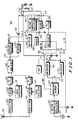
- Fig. 1 is a block diagram that shows a first embodiment of an AM-FM combined stereo receiver 100, according to the invention.
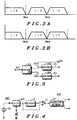
- Fig. 2A is a first spectrum diagram.
- Fig. 2B is a second spectrum diagram.
- Fig. 3 is a block diagram for a quadrature network according to the invention.
- Fig. 4 is an expanded block diagram of the pilot tone VCO and quadrature network.
- Fig. 5 is an expanded block diagram of the pilot tone VCO.
- Fig. 6 is a block diagram of the pilot tone threshold circuit.
- Fig. 1 is a block diagram that shows a first embodiment of an AM-FM combined stereo receiver 100, according to the invention.
- Fig. 1 there is shown the circuit flow structure from the antenna input 101 to the L + R and L - R outputs. Much of this circuitry is described in some detail in other patent applications that will be cited.
- the RF front end which includes the preselector, mixer and local oscillator (LO) is similar to most low voltage combined AM/FM stereo IC's (see, for instance, Block diagram TA8122).
- This signal is propagated in the AM broadcast band which spectrally extends from 520 kHz to 1710 kHz.
- the antenna 101 receives the electromagnetic wave and converts it into an AC voltage and current. This current is applied to the input of the preselector 103.
- the preselector is a radio frequency filtering circuit which partially removes signals other than the desired station (A * cos (w c t + ⁇ )).
- This circuit is typically composed of one or two resonant circuits, which are constructed of inductors and tunable capacitors or varactors.
- the AM and FM antennas are often separate.
- the AM antenna is generally a coil with a large ferrite or powdered iron core though it and is tuned with the variable capacitor.
- This antenna referred to as a loop stick', performs the function of antenna and preselector in the same drcuit.
- the preselected signal is then supplied to the mixer circuit 105.
- the mixer can be described as a circuit that multiplies the preselected RF with a reference signal supplied by the local oscillator 111. Mixing in the time domain is equivalent to adding and subtracting in the frequency domain.
- the output frequency from the mixer 105 is the absolute value of the preselected RF signal minus the local oscillator frequency.
- Intermediate Frequency (e. g., IF).
- the local oscillator 111 is designed such that when it is at the desired frequency, which when mixed with the preselected RF produces the desired IF, that the RF carrier is at the center frequency of the preselector filtering. This is generally defined in the industry as being 'tracked'. The above approach is described as a superheterodyne receiver.
- the IF signal is then further filtered to eliminate other interfering signals by the IF filter 107.
- the expected input is also of the form A * cos (w c t + ⁇ ).
- the ⁇ term is a frequency deviation of the baseband term shown in Fig. 2A.
- this baseband signal has the Left + Right (L + R) signal described as normal monophonic audio.
- the Left-Right signal is a double sideband suppressed carrier signal (DSBSC) where the suppressed carrier is at 38 kHz.
- a pilot tone is added at 19 kHz, that is phase coherent with the suppressed carrier (38 kHz) term, such that it can be used to derive a reference signal in the FM Stereo decoder.
- This signal will be necessary to translate the L - R signal to 0 Hz (D. C.) which is necessary to develop the correct stereo output.
- the baseband FM Stereo signal modulates the carrier such that the peak carrier deviation is 75 kHz.
- the FM antenna is generally a whip (e. g., straight piece of wire) or a home roof mounted antenna.
- This circuit as with the AM receiver converts the electromagnetic wave into a voltage and current.
- the signal is supplied to the preselector 113, which as described for the AM receiver is made of inductors and capacitors, and partially removes signals other than the desired carrier.
- This preselected signal is then converted in the mixer 115 to the desired IF frequency.
- the signal is further filtered in the IF filter 119 to remove interfering signals. This is defined as a superhetrodyne receiver and is well know in the industry.
- both the AM and FM signals go though relatively the same process to be converted to an IF signal 179.
- the major difference is that the AM RF signal is at 520 kHz to 1710 kHz and is converted to an IF of 450 kHz, whereas the FM signal is at 88 MHz to 108 MHz and is converted into a 10.7 MHz IF signal.
- the output of the IF amplifier 109 is connected into the envelope detector circuit 141 along with other circuits.
- This block supplies both amplification and the narrow band AGC action for the radio.
- the gain is necessary to supply the decoder with large enough signal levels that the decoding is accurate.
- the AGC function is necessary to hold the output signal (179) at the desired level.
- the envelope detector 141 performs the function of multiplying the IF signal 179, A * cos (w i t + ⁇ ) by the limited form of A * cos (w i t + ⁇ ) or sgn ⁇ cos (w i t + ⁇ ) ⁇ , where sgn is the signum function.
- This multiplication can be written as A * cos (w i t + ⁇ ) * sgn ⁇ cos (w i t + ⁇ ) ⁇ , which results in (A/2) + (A * cos (2(w i t + ⁇ ))/2). Any scaling of the A term in the demodulation process is ignored for convenience.
- the (A/2) * cos (2(w i t + ⁇ )) term is removed by an audio lowpass filter and only the A/2 tem is left. In the AM mode the A term is 1 + Left + Right. In the FM mode 'A' is the envelope multipath term and could, in high performance receivers, be used as an indication of the signal quality.
- the first embodiment includes the limiter 143, multiplier 153 and resonant circuit 137, 139 which form a discriminator circuit for the FM mode.
- VCO voltage controlled oscillator
- PLL phase locked loop
- switches 129, 131, 133 and 135 are both all set to the position designated F.
- switches 129, 131, 133 and 135 are set to the position designated A.
- a * cos (w i t + ⁇ ) is supplied to the input of the limiter 143.
- the limiter as explained previously removes the amplitude modulation (A).
- This circuit is similar in function to the generic part MC1355. Therefore the output from the limiter 143, supplied to the multiplier 153, is sgn ⁇ cos (w i t + ⁇ ) ⁇ , where sgn is the signum function.
- This multiplier circuit 153 is similar to the generic part MC1596.
- the voltage controlled oscillator 161 operates at a center frequency partially controlled by the resonant frequency of the inductor and capacitor 137, 139.
- the VCO steering voltage 175 is supplied by the output of the PLL filter 165. This voltage 175 causes a small variation in the operating frequency of the oscillator, which ideally is linearly proportional to the difference between the nominal reference voltage (VCO control voltage at center frequency) minus the PLL filter voltage.
- This VCO is similar to the FM oscillator of the oscillator / modulator section of the Motorola part MC1376.
- a resonant frequency of 10.8 MHz is chosen for AM.
- the divider 163 is set to divide the frequency of the VCO signal 177 by 24. Therefore the incoming signal, which is at 10.8 MHz, is divided by 24 and the outgoing signal is at 450 kHz, and w vco will be defined as 2 * ⁇ * F vco (450kHz).
- Both the limiter 143 output sgn ⁇ cos (w i t + ⁇ ) ⁇ and the divider 163 output sgn ⁇ cos (w vco ) ⁇ are supplied to the multiplier 153.
- the output of the multiplier 153 is therefore ⁇ (w i t + ⁇ ) + (w vco t) ⁇ /2 + ⁇ (w i t + ⁇ ) - (w vco t) ⁇ /2.
- This output signal is then filtered in the capacitor 159 shown attached to the multiplier 153. Since w vco and w i are significantly higher in frequency than audio and approximately the same frequency, the filter 159 can easily remove the (w i t + w vco t) term. This results in ⁇ (w i t + ⁇ ) - (w vco t) ⁇ being the output of the multiplier 153.
- Circuitry in the tangent generator 155 and multiplier 157 which will be described later, converts (w i t + ⁇ - w vco t) into (A) * tan ⁇ (w i t + ⁇ ) - (w vco t) ⁇ .
- This signal is supplied to the PLL filter 165 to control the frequency of the VCO 161.
- the circuit is set to the FM configuration.
- the signal 179 supplied to the limiter 143 can be defined as A * cos ⁇ w i t + 2 ⁇ f d ⁇ m(t)d(t) ⁇ , where m(t) is the modulation and fd is the frequency deviation constant.
- the exact details of FM demodulation in a limiter discriminated approach as shown above is well described in communication texts such as the ITT Reference Data handbook for Radio Engineers or Principles of Communications by Ziemer and Tranter.
- This circuit can be implemented using a CA3089.
- the FM modulation can be described as moving the center frequency of the carrier by the amplitude of the modulation. Therefore, for FM stereo, the signal can be described as the baseband signal shown in Fig. 2A. Included is the L + R signal in the 0 to 15 kHz region and the L - R signal which is a double sideband suppressed carrier signal (DSBSC) where the suppressed carrier is at 38 kHz, while the pilot tone is at 19 kHz.
- DSBSC double sideband suppressed carrier signal
- This baseband signal is used to change the frequency of the carrier, where each instantaneous amplitude of the baseband can map into an instantaneous deviation of the carrier frequency.
- the limiter 143 removes any AM modulation which may have been accidently induced in the propagation channel.
- the limiter 143 also turns the carrier sine wave into a square wave, e. g., sgn.(cos (w i t + ⁇ )).
- This signal is supplied to both the resonant drcuit 137, 139 and the multiplier 153.
- the phase response vs. carrier frequency characteristic of the resonant circuit 137, 139 is tan -1 ((freq(instantaneous) - freq. (average))/freq. (bandwidth/2)) + 90°.
- the resultant multiplication in multiplier (153) has the limited incoming IF signal sgn.
- Switch 133 connects to the resonant circuit 137, 139 and connects either the VCO 161 to drive this circuit for the PLL approach or it connects the limiter 143 through a phase shifting capacitor 151 to drive the discriminator circuit.
- Switch 135 connects the multiplier 153 altemate port to either the divider 163 for the AM PLL or directly to the resonant network 137, 139 for the limiter discriminator FM approach.
- the shifting of the resonant circuit 137, 139 to 100 kHz lower in frequency for FM can by be easily accomplished by the specific choice of capacitor value. It is conceivable that in some applications a PLL decoder would be desired for FM along with AM. In this situation switch 133 would not be needed. Therefore in this case switch 135 would be selecting whether the PLL would be operating at 10.7 MHz or 450 kHz.
- This approach is described in Norman W. Parker, et al., "AM Stereophonic Receiver," U. S. Patent 4,172,966.
- the tangent function generator 155 can be built using many different approaches.
- One approach using a precision piecewise linear construction is described in Charles J. Marik, "Tangent Function Generator For AM Stereo", U. S. Patent 4,278,839, issued July 14, 1981.
- the FM signal should be an exact replica of the transmitter baseband signal as shown in Fig. 2A.
- this signal has the L + R audio in the correct form, in other words the L + R DC term is at 0 Hz. Therefore, this signal can be used directly to supply the L + R term for the matrix.
- the double sideband suppressed carrier signal must be converted around DC.
- ⁇ (L - R) * cos (wt) * cos (wt) ⁇ ⁇ (L R)/2 ⁇ * cos (0) + ⁇ (L - R)/2 ⁇ * cos (2wt). Since the 2w i t term is at 76kHz, it is generally not a concern.
- the 38 kHz multiplying signal is derived in the pilot tone detector and will be discussed later. This signal is supplied to the decoder multiplier (157) along with the linearized baseband signal. The resulting spectrum out of (157) is shown in Fig. 2B.
- the L - R term is referenced at DC and can therefore be used to supply the audio matrix (not show).
- the 19 kHz pilot tone is multiplied by 38 kHz producing two new signals one at 19 kHz and the other at 57 kHz.
- the L + R signal which was at baseband has been multiplied by the 38 kHz carrier and becomes a 38 kHz double sideband suppressed carrier signal.
- the previous multipliers used in the radio could be of the MC1596 chopper type
- the multiplier 157 must be of a type possibly similar to a MC1595.
- the pilot tone detector for both the AM and FM signals consists of, the I multiplier (145), the Q multiplier (147), the quadrature generator (127), the VCO (125), 1 filter capacitor (149), loop filter capacitor (123) and threshold detector 502. This is shown in Fig. 1.
- the pilot tone detector structure is similar to that of a LM567C tone decoder or the decoder described in Lawrence M. Ecklund, "Tone Detector with Pseudo Phase Locked Loop," U. S. Patent 4,618,981, issued October 21, 1986, which patent is hereby incorporated by reference.
- the structure of the tone decoder can be basically divided into two parts. The first part includes the Q detector (147) , VCO (125), loop filter (123) and quadrature generator (127).
- the second part of the detector includes the I multiplier (145), I filter (149), quadrature network (127), VCO (125) and threshold detector 502.
- the I detector develops a DC voltage which corresponds to the amplitude of the pilot tone.
- this voltage reaches a preset level it triggers the threshold detector (502) which indicates to the user, through some interface device, that the station is in stereo.
- the pilot tone is at 25Hz and is present in the L - R signal at the output of the decoder multiplier (157).
- This pilot tone is present with all the other L - R audio information and is at a value of 5% with respect to the maximum L - R information.
- the signal is supplied to one port of multiplier (147) and multiplier (145).
- the other port in the Q multiplier is supplied by sin (2 ⁇ * 25t).
- the VCO is to be used for FM stereo where the pilot frequency is 19kHz and a phase accurate 38kHz signal must be generated. Further the same VCO is used for AM Stereo where the frequency of the pilot is 25Hz.
- One relatively easy way to accommodate this delta in frequency is to place a digital divider circuit between the VCO (125) and the Quadrature generator (127). this is shown in attached Fig. 4.
- the VCO (125) frequency for FM is 76kHz and the quadrature generator (127) is a + 4 circuit.
- the quadrature network is formed of three divide by 2 circuits shown in Fig. 3 and will be discussed in the FM section later. Retuming to Fig. 4 in the FM mode the VCO (125) is connected directly through the switch 3 to the quadrature generator (127) and the output frequency to the multipliers is 76kHz+4 or 19kHz. For the AM mode the frequency into the quadrature generator is 100Hz to supply the 25Hz reference signal to the multipliers. Therefore, the divide number for divider 2 is 760. This divider is similar to MC14024, but requiring 11 divider stages to generate division by 760.
- FIG. 5 A second form of the VCO which is more practical for some applications is shown in Fig. 5.
- a dual PLL is used and the VCO's could have an operation similar to a LM565.
- the main reason for this approach is to avoid the extemal resonant element (121) shown in Fig. 1, develop a DC voltage that corresponds to a given VCO frequency and also reducing any spurious signals that the resonant element may produce in the broadcast band.
- the first PLL 402 is used to derive the correct nominal Vpll voltage for VCO (125).
- the resistive and capacitive elements to form 406 and 121 are constructed on the decoder IC. In Integrated Circuits the absolute value of components is poor, but the matching between similar components is very good.
- the voltage 'Vpll' 403 which will give the VCO in PLL (402) of Fig. 5 a frequency F, will also give the VCO (125) frequency F, provided that the resonator elements (121) are constructed on the same die with that of 406. Given this phenomena, and that 402 frequency locks and conditions (removes the modulation) of the output of 404, the VCO (125) has the same free running frequency as the output of 404. Therefore, this processing could use the output of the limiter (143), resonant element (137, 139) or the decoder divider (163) divided by 404 to supply the desired VCO (125) nominal operating frequency.
- a possible variation of this approach is to scale the resistive and capacitive elements of (121) and 406 that set the center frequency of the two VCO's. Since, the ratio of the IC elements is good, the frequency setting resistor and capacitor (121) of the second VCO can be made larger than the first VCO thus lowering the frequency of the second VCO, minimizing the number of divider sections needed in 404
- Fig. 6 shows a detailed picture of the pilot indicator circuit.
- Actual indication of the pilot tone comes from the I detector (145).
- the circuit has a cos (2 ⁇ ⁇ 25t) reference signal (171) supplied from the quadrature generator of the pilot tone PLL.
- the other signal supplied to the I detector is L - R, which as previously stated contains (.05) * cos (2 ⁇ * 25t) for AM stereo.
- This multiplier output is filtered by the capacitor (149) and compared with a reference threshold 'VBB' as shown. If the size of the signal is large enough to exceed the pilot tone level reference level 'VBB' then the output of the threshold detector goes high indicating a stereo station is present.
- the 19 kHz composite baseband signal including the FM pilot tone is supplied to the pilot tone I and Q multipliers 145, 147 from the output of the tangent linearizing circult 155.
- the pilot tone detector can be separated into two major components. Also as before these components are the PLL pilot tone extraction system and the actual detection of the pilot tone level. There are some gain and level changes that are necessary In the PLL depending upon the K1 term in the discriminator. Assuming that the output gain of the tangent function 155 is switched so that 100% AM modulation is the same as 100% FM modulation. Then the only changes necessary are to switch out the divider 163, as shown in Fig. 4 and change the value of VBB to 9/5 higher to account for the 9% FM pilot level versus the 5% pilot level for AM stereo.
- the structure of the quadrature generator 127 which is similar to that of the MC1310, is shown in Fig. 3.
- the 76 kHz input 167 is supplied to the input of the first divider 301 and is divided by 2.
- This divider has two outputs 207, 309 at 38 kHz which are 180° out of phase with each other.
- the 0° output 307 is supplied as the (38 kHz) drive signal 169 to the FM stereo decoder.
- This output 307 is also supplied to another + 2 circuit 303 whose output supplies the I pilot tone multiplier 145.
- the -180° output supplies another + 2 circuit 305 whose output supplies the reference signal 173 for the Q pilot tone multiplier 147. This technique is well known.
Landscapes
- Engineering & Computer Science (AREA)
- Signal Processing (AREA)
- Computer Networks & Wireless Communication (AREA)
- Stereo-Broadcasting Methods (AREA)
- Circuits Of Receivers In General (AREA)
- Transmitters (AREA)
Applications Claiming Priority (3)
| Application Number | Priority Date | Filing Date | Title |
|---|---|---|---|
| US651713 | 1991-02-06 | ||
| US07/651,713 US5239699A (en) | 1991-02-06 | 1991-02-06 | Am-fm combined stereo receiver |
| PCT/US1992/000885 WO1992014311A1 (en) | 1991-02-06 | 1992-02-04 | Am-fm combined stereo receiver |
Publications (3)
| Publication Number | Publication Date |
|---|---|
| EP0570481A1 EP0570481A1 (en) | 1993-11-24 |
| EP0570481A4 EP0570481A4 (enExample) | 1994-01-19 |
| EP0570481B1 true EP0570481B1 (en) | 1997-08-27 |
Family
ID=24613917
Family Applications (1)
| Application Number | Title | Priority Date | Filing Date |
|---|---|---|---|
| EP92905676A Expired - Lifetime EP0570481B1 (en) | 1991-02-06 | 1992-02-04 | Am-fm combined stereo receiver |
Country Status (8)
| Country | Link |
|---|---|
| US (1) | US5239699A (enExample) |
| EP (1) | EP0570481B1 (enExample) |
| JP (1) | JP2713001B2 (enExample) |
| AU (1) | AU645408B2 (enExample) |
| CA (1) | CA2100444C (enExample) |
| DE (1) | DE69221850T2 (enExample) |
| TW (1) | TW208764B (enExample) |
| WO (1) | WO1992014311A1 (enExample) |
Families Citing this family (11)
| Publication number | Priority date | Publication date | Assignee | Title |
|---|---|---|---|---|
| DE4340012B4 (de) * | 1993-11-24 | 2004-04-22 | Blaupunkt-Werke Gmbh | Demodulator |
| US5715528A (en) * | 1996-02-08 | 1998-02-03 | Ford Motor Company | Converting capacitance to inductance in a floating resonant |
| US6041280A (en) * | 1996-03-15 | 2000-03-21 | Sirf Technology, Inc. | GPS car navigation system |
| US6810266B1 (en) * | 1999-11-16 | 2004-10-26 | Freescale Semiconductor, Inc. | Digitally controlled radio back-end |
| US6473605B1 (en) * | 1999-11-16 | 2002-10-29 | Motorola, Inc. | Noise reduction and range control radio system |
| US6473606B1 (en) * | 1999-11-16 | 2002-10-29 | Motorola, Inc. | Common intermediate frequency broadcast radio front end |
| KR100690954B1 (ko) * | 2000-01-19 | 2007-03-09 | 코닌클리케 필립스 일렉트로닉스 엔.브이. | 무선 fm 수신기 |
| WO2003026156A1 (en) * | 2001-09-18 | 2003-03-27 | Koninklijke Philips Electronics N.V. | Rf signal switch for a wireless communication device |
| US8036402B2 (en) * | 2005-12-15 | 2011-10-11 | Harman International Industries, Incorporated | Distortion compensation |
| US20070178863A1 (en) * | 2006-01-27 | 2007-08-02 | Tuttle G Tyson | AM/FM tuner saw filter-less architecture using AM frequency band up-conversion |
| CN203644936U (zh) * | 2010-12-30 | 2014-06-11 | 硅实验室公司 | 共享的am/fm天线电路以及am/fm无线电接收机系统 |
Family Cites Families (11)
| Publication number | Priority date | Publication date | Assignee | Title |
|---|---|---|---|---|
| US3665507A (en) * | 1971-01-04 | 1972-05-23 | Gen Electric | Signal processor for reception of amplitude or frequency modulated signals |
| US4170716A (en) * | 1977-10-14 | 1979-10-09 | Motorola, Inc. | AM stereo receiver with correction limiting |
| US4172966A (en) * | 1978-02-23 | 1979-10-30 | Motorola, Inc. | AM stereophonic receiver |
| US4324952A (en) * | 1978-08-21 | 1982-04-13 | Harris Corporation | Direct function receivers and transmitters for multichannel communications system |
| US4278839A (en) * | 1979-08-02 | 1981-07-14 | Motorola, Inc. | Tangent function generator for AM stereo |
| DE3024085A1 (de) * | 1980-06-27 | 1982-01-21 | Philips Patentverwaltung Gmbh, 2000 Hamburg | Am-fm-rundfunkempfaenger zum empfang von am-stereosignalen |
| US4388496A (en) * | 1980-08-11 | 1983-06-14 | Trio Kabushiki Kaisha | FM/AM Stereo receiver |
| US4426728A (en) * | 1981-08-31 | 1984-01-17 | Kahn Leonard R | Multiple system AM stereo receiver and pilot signal detector |
| US4716590A (en) * | 1984-01-17 | 1987-12-29 | Sansui Electric Co., Ltd. | AM stereo transmission method and apparatus |
| US4872207A (en) * | 1987-04-15 | 1989-10-03 | Motorola, Inc. | Automatic IF tangent lock control circuit |
| US5109542A (en) * | 1991-02-06 | 1992-04-28 | Motorola, Inc. | AM-FM combined stereo receiver |
-
1991
- 1991-02-06 US US07/651,713 patent/US5239699A/en not_active Expired - Lifetime
-
1992
- 1992-02-04 CA CA002100444A patent/CA2100444C/en not_active Expired - Fee Related
- 1992-02-04 WO PCT/US1992/000885 patent/WO1992014311A1/en not_active Ceased
- 1992-02-04 AU AU13581/92A patent/AU645408B2/en not_active Ceased
- 1992-02-04 DE DE69221850T patent/DE69221850T2/de not_active Expired - Fee Related
- 1992-02-04 EP EP92905676A patent/EP0570481B1/en not_active Expired - Lifetime
- 1992-02-06 JP JP4054096A patent/JP2713001B2/ja not_active Expired - Fee Related
- 1992-05-18 TW TW081103854A patent/TW208764B/zh active
Also Published As
| Publication number | Publication date |
|---|---|
| CA2100444C (en) | 1998-11-24 |
| DE69221850D1 (de) | 1997-10-02 |
| WO1992014311A1 (en) | 1992-08-20 |
| JPH05114822A (ja) | 1993-05-07 |
| JP2713001B2 (ja) | 1998-02-16 |
| EP0570481A4 (enExample) | 1994-01-19 |
| CA2100444A1 (en) | 1992-08-07 |
| DE69221850T2 (de) | 1998-02-12 |
| EP0570481A1 (en) | 1993-11-24 |
| TW208764B (enExample) | 1993-07-01 |
| AU645408B2 (en) | 1994-01-13 |
| AU1358192A (en) | 1992-09-07 |
| US5239699A (en) | 1993-08-24 |
Similar Documents
| Publication | Publication Date | Title |
|---|---|---|
| US5507024A (en) | FM data-system radio receiver | |
| US5303413A (en) | AM radio receiver with switchable IF bandwidth | |
| US6483456B2 (en) | GPS receiver | |
| US7787630B2 (en) | FM stereo decoder incorporating Costas loop pilot to stereo component phase correction | |
| EP0570481B1 (en) | Am-fm combined stereo receiver | |
| WO1994014246A1 (en) | Generation of a coherent signal using an adaptive filter for cancelling and synchronous detection in a digital radio receiver | |
| EP0570508B1 (en) | Am-fm combined stereo receiver | |
| AU645669B2 (en) | AM-FM combined stereo receiver | |
| US6661292B2 (en) | Apparatus and method for demodulating a radio data system (RDS) signal | |
| US5442709A (en) | Circuit for decoding a multiplex signal in a stereo receiver | |
| US6704554B1 (en) | Frequency modulation receiver in particular for an RDS application | |
| CN102668387A (zh) | Fm接收器噪声降低 | |
| EP0141565B1 (en) | Am stereo signal decoder | |
| EP0420584B1 (en) | PLL demodulating circuit in traffic information receiver | |
| JP3827381B2 (ja) | Pll周波数シンセサイザ |
Legal Events
| Date | Code | Title | Description |
|---|---|---|---|
| PUAI | Public reference made under article 153(3) epc to a published international application that has entered the european phase |
Free format text: ORIGINAL CODE: 0009012 |
|
| 17P | Request for examination filed |
Effective date: 19930715 |
|
| AK | Designated contracting states |
Kind code of ref document: A1 Designated state(s): DE FR GB |
|
| A4 | Supplementary search report drawn up and despatched |
Effective date: 19931126 |
|
| AK | Designated contracting states |
Kind code of ref document: A4 Designated state(s): DE FR GB |
|
| GRAG | Despatch of communication of intention to grant |
Free format text: ORIGINAL CODE: EPIDOS AGRA |
|
| 17Q | First examination report despatched |
Effective date: 19961022 |
|
| GRAH | Despatch of communication of intention to grant a patent |
Free format text: ORIGINAL CODE: EPIDOS IGRA |
|
| GRAH | Despatch of communication of intention to grant a patent |
Free format text: ORIGINAL CODE: EPIDOS IGRA |
|
| GRAA | (expected) grant |
Free format text: ORIGINAL CODE: 0009210 |
|
| AK | Designated contracting states |
Kind code of ref document: B1 Designated state(s): DE FR GB |
|
| ET | Fr: translation filed | ||
| REF | Corresponds to: |
Ref document number: 69221850 Country of ref document: DE Date of ref document: 19971002 |
|
| PLBE | No opposition filed within time limit |
Free format text: ORIGINAL CODE: 0009261 |
|
| STAA | Information on the status of an ep patent application or granted ep patent |
Free format text: STATUS: NO OPPOSITION FILED WITHIN TIME LIMIT |
|
| 26N | No opposition filed | ||
| PGFP | Annual fee paid to national office [announced via postgrant information from national office to epo] |
Ref country code: GB Payment date: 20010104 Year of fee payment: 10 |
|
| PGFP | Annual fee paid to national office [announced via postgrant information from national office to epo] |
Ref country code: FR Payment date: 20010201 Year of fee payment: 10 |
|
| PGFP | Annual fee paid to national office [announced via postgrant information from national office to epo] |
Ref country code: DE Payment date: 20010228 Year of fee payment: 10 |
|
| REG | Reference to a national code |
Ref country code: GB Ref legal event code: IF02 |
|
| PG25 | Lapsed in a contracting state [announced via postgrant information from national office to epo] |
Ref country code: GB Free format text: LAPSE BECAUSE OF NON-PAYMENT OF DUE FEES Effective date: 20020204 |
|
| PG25 | Lapsed in a contracting state [announced via postgrant information from national office to epo] |
Ref country code: DE Free format text: LAPSE BECAUSE OF NON-PAYMENT OF DUE FEES Effective date: 20020903 |
|
| GBPC | Gb: european patent ceased through non-payment of renewal fee |
Effective date: 20020204 |
|
| PG25 | Lapsed in a contracting state [announced via postgrant information from national office to epo] |
Ref country code: FR Free format text: LAPSE BECAUSE OF NON-PAYMENT OF DUE FEES Effective date: 20021031 |
|
| REG | Reference to a national code |
Ref country code: FR Ref legal event code: ST |