EP0569727A1 - Fuel supply line arrangement for an injection nozzle - Google Patents
Fuel supply line arrangement for an injection nozzle Download PDFInfo
- Publication number
- EP0569727A1 EP0569727A1 EP93106120A EP93106120A EP0569727A1 EP 0569727 A1 EP0569727 A1 EP 0569727A1 EP 93106120 A EP93106120 A EP 93106120A EP 93106120 A EP93106120 A EP 93106120A EP 0569727 A1 EP0569727 A1 EP 0569727A1
- Authority
- EP
- European Patent Office
- Prior art keywords
- cylinder head
- injection nozzle
- pipe socket
- inlet
- fuel supply
- Prior art date
- Legal status (The legal status is an assumption and is not a legal conclusion. Google has not performed a legal analysis and makes no representation as to the accuracy of the status listed.)
- Granted
Links
Images
Classifications
-
- F—MECHANICAL ENGINEERING; LIGHTING; HEATING; WEAPONS; BLASTING
- F02—COMBUSTION ENGINES; HOT-GAS OR COMBUSTION-PRODUCT ENGINE PLANTS
- F02M—SUPPLYING COMBUSTION ENGINES IN GENERAL WITH COMBUSTIBLE MIXTURES OR CONSTITUENTS THEREOF
- F02M61/00—Fuel-injectors not provided for in groups F02M39/00 - F02M57/00 or F02M67/00
- F02M61/16—Details not provided for in, or of interest apart from, the apparatus of groups F02M61/02 - F02M61/14
- F02M61/165—Filtering elements specially adapted in fuel inlets to injector
-
- F—MECHANICAL ENGINEERING; LIGHTING; HEATING; WEAPONS; BLASTING
- F02—COMBUSTION ENGINES; HOT-GAS OR COMBUSTION-PRODUCT ENGINE PLANTS
- F02M—SUPPLYING COMBUSTION ENGINES IN GENERAL WITH COMBUSTIBLE MIXTURES OR CONSTITUENTS THEREOF
- F02M55/00—Fuel-injection apparatus characterised by their fuel conduits or their venting means; Arrangements of conduits between fuel tank and pump F02M37/00
- F02M55/004—Joints; Sealings
- F02M55/005—Joints; Sealings for high pressure conduits, e.g. connected to pump outlet or to injector inlet
-
- F—MECHANICAL ENGINEERING; LIGHTING; HEATING; WEAPONS; BLASTING
- F02—COMBUSTION ENGINES; HOT-GAS OR COMBUSTION-PRODUCT ENGINE PLANTS
- F02M—SUPPLYING COMBUSTION ENGINES IN GENERAL WITH COMBUSTIBLE MIXTURES OR CONSTITUENTS THEREOF
- F02M55/00—Fuel-injection apparatus characterised by their fuel conduits or their venting means; Arrangements of conduits between fuel tank and pump F02M37/00
- F02M55/02—Conduits between injection pumps and injectors, e.g. conduits between pump and common-rail or conduits between common-rail and injectors
-
- F—MECHANICAL ENGINEERING; LIGHTING; HEATING; WEAPONS; BLASTING
- F02—COMBUSTION ENGINES; HOT-GAS OR COMBUSTION-PRODUCT ENGINE PLANTS
- F02M—SUPPLYING COMBUSTION ENGINES IN GENERAL WITH COMBUSTIBLE MIXTURES OR CONSTITUENTS THEREOF
- F02M61/00—Fuel-injectors not provided for in groups F02M39/00 - F02M57/00 or F02M67/00
- F02M61/14—Arrangements of injectors with respect to engines; Mounting of injectors
Definitions
- the invention is based on a fuel supply device for an injection nozzle used in a cylinder head of an internal combustion engine according to the preamble of claim 1.
- a fuel supply device of this type the pipe socket and also the connecting piece of the inlet pipe are completely accommodated in the passage of the cylinder head. This arrangement probably compensates for an offset of the nozzle holder of the injection nozzle in the cylinder head, but it can only be installed together with the inlet pipe brought up by the injection pump.
- a particularly easy-to-assemble fuel supply device results if it is designed in accordance with the characterizing part of claim 1, so that the injection nozzle and the pipe socket can be installed simultaneously and, independently of this, the pressure or supply pipe at a later point in time, preferably when the injection pump is connected , can be connected in a simple and clear manner.
- a sealing ring is arranged in the collar of the pipe socket, which is preferably located in the pivot point of the pipe socket, a completely sealed arrangement is provided. Further it is advantageous to arrange a rod filter in the pipe socket according to claim 4.
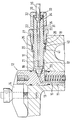
- FIG. 1 An embodiment of the invention is shown in the drawing, which shows part of a cylinder head of an internal combustion engine and a fuel supply device for an injection nozzle in section, and is explained in more detail below.
- an injection nozzle 12 is inserted in a bore 11 leading to the combustion chamber, the nozzle holder 13 of which is held stationary by a claw 14.
- the nozzle holder 13 has a laterally open inlet channel 15, in which a bore with a conical seat surface 16 is made open to the periphery of the nozzle holder 13.
- a passage is arranged in the cylinder head 10 in the form of a stepped bore 17 which passes through a pipe socket 20.
- the pipe socket 20 has an axial bore 21 with an extension 22 in the inlet-side end section 23, in which a rod filter 24 known per se is inserted.
- the pipe socket 20 Approximately in the middle of its longitudinal extension, the pipe socket 20 has a collar 25 with a spherical shoulder 26, on which a union screw 28 screwed into the extension 18 of the bore 17 engages the pipe socket 20 against the nozzle holder 13.
- the pipe socket 20 In order to ensure a tight connection even when the nozzle holder 13 is axially offset, the pipe socket 20 has a spherical cone 29 at its outlet-side end section, which is clamped against the conical seat surface 16 of the nozzle holder 13.
- the inlet-side end section 23 of the pipe socket 20 protrudes from the bore 17 in the cylinder head 10 and carries an external thread 31.
- a union screw 32 is screwed onto this, which, via a washer 33, a conical connecting piece 34 on an inlet pipe 35 against a conical seat surface 36 at the inlet the bore 21 or extension 22 presses.
- An O-ring 40 inserted in a circumferential groove 41 of the collar 20, the outer side of which rests against the wall of the bore 17, seals the annular gap surrounding the pipe socket 20 to the outside.
Abstract
Description
Die Erfindung geht aus von einer Kraftstoffzuleitungseinrichtung für eine in einem Zylinderkopf einer Brennkraftmaschine eingesetzten Einspritzdüse nach der Gattung des Anspruchs 1. Bei einer bekannten Kraftstoffzuleitungseinrichtung dieser Gattung sind der Rohrstutzen und auch das Anschlußstück des Zulaufrohrs vollständig im Durchgang des Zylinderkopfs untergebracht. Diese Anordnung gleicht wohl einen Versatz des Düsenhalters der Einspritzdüse im Zylinderkopf aus, ihre Montage ist jedoch nur zusammen mit dem von der Einspritzpumpe herangeführten Zulaufrohr möglich.The invention is based on a fuel supply device for an injection nozzle used in a cylinder head of an internal combustion engine according to the preamble of claim 1. In a known fuel supply device of this type, the pipe socket and also the connecting piece of the inlet pipe are completely accommodated in the passage of the cylinder head. This arrangement probably compensates for an offset of the nozzle holder of the injection nozzle in the cylinder head, but it can only be installed together with the inlet pipe brought up by the injection pump.
Eine besonders einfach zu montierende Kraftstoffzuleitungseinrichtung ergibt sich, wenn diese gemäß dem kennzeichnenden Teil des Anspruchs 1 ausgestaltet ist, so daß die Einspritzdüse und der Rohrstutzen gleichzeitig montiert werden können und davon unabhängig das Druck- oder Zulaufrohr zu einem späteren Zeitpunkt, vorzugsweise beim Anschließen der Einspritzpumpe, in einfacher und übersichtlicher Weise angeschlossen werden kann.A particularly easy-to-assemble fuel supply device results if it is designed in accordance with the characterizing part of claim 1, so that the injection nozzle and the pipe socket can be installed simultaneously and, independently of this, the pressure or supply pipe at a later point in time, preferably when the injection pump is connected , can be connected in a simple and clear manner.
Wenn außerdem gemäß Anspruch 3 im Bund des Rohrstutzens ein Dichtring angeordnet ist, der vorzugsweise im Schwenkpunkt des Rohrstutzens liegt, ist eine völlig dichte Anordnung gegeben. Ferner ist es vorteilhaft, gemäß Anspruch 4 im Rohrstutzen ein Stabfilter anzuordnen.If, in addition, a sealing ring is arranged in the collar of the pipe socket, which is preferably located in the pivot point of the pipe socket, a completely sealed arrangement is provided. Further it is advantageous to arrange a rod filter in the pipe socket according to claim 4.
Ein Ausführungsbeispiel der Erfindung ist in der Zeichnung dargestellt, die einen Teil eines Zylinderkopfes einer Brennkraftmaschine und eine Kraftstoffzuleitungseinrichtung für eine Einspritzdüse im Schnitt zeigt, und wird im folgenden näher erläutert.An embodiment of the invention is shown in the drawing, which shows part of a cylinder head of an internal combustion engine and a fuel supply device for an injection nozzle in section, and is explained in more detail below.
In einem Zylinderkopf 10 einer Brennkraftmaschine ist in einer zum Brennraum führenden Bohrung 11 eine Einspritzdüse 12 eingesetzt, deren Düsenhalter 13 von einer Klaue 14 ortsfest gehalten wird. Zum Zuführen von Kraftstoff hat der Düsenhalter 13 einen seitlich offenen Zulaufkanal 15, in dem eine zum Umfang des Düsenhalters 13 offene Bohrung mit einer kegeligen Sitzfläche 16 angebracht ist. In Ausrichtung zu dieser Sitzfläche 16 ist im Zylinderkopf 10 ein Durchgang in Form einer gestuften Bohrung 17 angeordnet, die ein Rohrstutzen 20 durchsetzt.In a
Der Rohrstutzen 20 hat eine axiale Bohrung 21 mit einer Erweiterung 22 im einlaufseitigen Endabschnitt 23, in der ein an sich bekanntes Stabfilter 24 eingesetzt ist. Etwa in der Mitte seiner Längserstreckung hat der Rohrstutzen 20 einen Bund 25 mit einer balligen Schulter 26, an der eine in die Erweiterung 18 der Bohrung 17 eingeschraubte Überwurfschraube 28 angreifend den Rohrstutzen 20 gegen den Düsenhalter 13 spannt. Um einen dichten Anschluß auch bei axialem Versatz des Düsenhalters 13 sicherzustellen, hat der Rohrstutzen 20 an seinem auslaufseitigen Endabschnitt einen balligen Kegel 29, der gegen die kegelige Sitzfläche 16 des Düsenhalters 13 gespannt ist.The
Der zulaufseitige Endabschnitt 23 des Rohrstutzens 20 ragt aus der Bohrung 17 im Zylinderkopf 10 vor und trägt ein Außengewinde 31. Auf dieses ist eine Überwurfschraube 32 aufgeschraubt, die über eine Scheibe 33 ein kegeliges Anschlußstück 34 an einem Zulaufrohr 35 gegen eine konische Sitzfläche 36 am Einlaß der Bohrung 21 bzw. Erweiterung 22 drückt. Ein in einer Umfangsnut 41 des Bundes 20 eingelegter O-Ring 40, der mit seiner Außenseite an der Wand der Bohrung 17 anliegt, dichtet den den Rohrstutzen 20 umgebenden Ringspalt nach außen ab.The inlet-
Claims (4)
Applications Claiming Priority (2)
| Application Number | Priority Date | Filing Date | Title |
|---|---|---|---|
| DE9206268U | 1992-05-09 | ||
| DE9206268U DE9206268U1 (en) | 1992-05-09 | 1992-05-09 | Fuel supply device for an injection nozzle |
Publications (2)
| Publication Number | Publication Date |
|---|---|
| EP0569727A1 true EP0569727A1 (en) | 1993-11-18 |
| EP0569727B1 EP0569727B1 (en) | 1995-12-13 |
Family
ID=6879319
Family Applications (1)
| Application Number | Title | Priority Date | Filing Date |
|---|---|---|---|
| EP93106120A Expired - Lifetime EP0569727B1 (en) | 1992-05-09 | 1993-04-15 | Fuel supply line arrangement for an injection nozzle |
Country Status (4)
| Country | Link |
|---|---|
| EP (1) | EP0569727B1 (en) |
| JP (1) | JP3616650B2 (en) |
| BR (1) | BR9301773A (en) |
| DE (2) | DE9206268U1 (en) |
Cited By (21)
| Publication number | Priority date | Publication date | Assignee | Title |
|---|---|---|---|---|
| FR2698408A1 (en) * | 1992-11-21 | 1994-05-27 | Daimler Benz Ag | Cylinder head for an internal combustion engine. |
| US5617828A (en) * | 1995-07-05 | 1997-04-08 | Robert Bosch Gmbh | Fuel injection valve for internal combusiton engines |
| DE19543506A1 (en) * | 1995-11-22 | 1997-05-28 | Man Nutzfahrzeuge Ag | Injection line connection to compression tube of injection valve |
| GB2310891A (en) * | 1996-03-06 | 1997-09-10 | Bosch Gmbh Robert | Fuel feed connection |
| US5775303A (en) * | 1995-06-30 | 1998-07-07 | Cummins Engine Company, Inc. | High Pressure Fuel Line Connection |
| WO1999000594A1 (en) | 1997-06-28 | 1999-01-07 | Robert Bosch Gmbh | Fuel supply device |
| WO1999028617A1 (en) | 1997-12-03 | 1999-06-10 | Robert Bosch Gmbh | Fuel injection device |
| EP0974749A2 (en) * | 1998-07-24 | 2000-01-26 | Lucas Industries Limited | Connector for use in supplying fuel to an injector |
| WO2000026529A1 (en) * | 1998-11-02 | 2000-05-11 | Robert Bosch Gmbh | Retaining body for a fuel injection valve in an internal combustion engine |
| EP1001162A2 (en) * | 1998-11-12 | 2000-05-17 | Lucas Industries Limited | Injector and injector assembly |
| EP1241348A2 (en) * | 2001-03-13 | 2002-09-18 | Robert Bosch Gmbh | High pressure connection for fuel injection system |
| EP0937892A3 (en) * | 1998-02-24 | 2003-01-02 | Man Nutzfahrzeuge Ag | Device for removing pressure tubes from injection units in internal combustion engines |
| WO2005035970A1 (en) * | 2003-10-06 | 2005-04-21 | Robert Bosch Gmbh | Injection nozzle |
| EP1985841A1 (en) * | 2007-04-27 | 2008-10-29 | Continental Automotive GmbH | Fluid inlet arrangement for an injection valve and injection valve |
| EP2060775A2 (en) | 2007-11-13 | 2009-05-20 | Delphi Technologies, Inc. | Fuel lance and assembly |
| DE102009029116A1 (en) | 2009-09-02 | 2011-03-03 | Robert Bosch Gmbh | Fuel injector |
| EP2354529A1 (en) * | 2010-01-21 | 2011-08-10 | Delphi Technologies Holding S.à.r.l. | Fuel Pipe Assembly and Clamping Means |
| WO2012059270A1 (en) * | 2010-11-04 | 2012-05-10 | Robert Bosch Gmbh | Device for the media-tight connection of two high-pressure components |
| US8272368B2 (en) | 2008-06-19 | 2012-09-25 | Westport Power Inc. | Dual fuel connector |
| CN103807525A (en) * | 2012-11-12 | 2014-05-21 | Ti汽车海德堡有限公司 | Screw connection device for conduits, in particular for motor vehicle conduits |
| WO2017007709A1 (en) * | 2015-07-08 | 2017-01-12 | Entegris, Inc. | High pressure filter |
Families Citing this family (5)
| Publication number | Priority date | Publication date | Assignee | Title |
|---|---|---|---|---|
| DE19526693A1 (en) * | 1995-07-21 | 1997-01-23 | Man Nutzfahrzeuge Ag | Injection valve for air-compressing internal combustion engines |
| DE19814501A1 (en) * | 1998-04-01 | 1999-10-07 | Bosch Gmbh Robert | Fuel injection valve for internal combustion engines |
| CN1945119B (en) * | 2006-11-16 | 2010-06-23 | 贵阳铝镁设计研究院 | Cathode roasting furnace gas burner nozzle |
| AT509177B1 (en) * | 2009-11-23 | 2013-09-15 | Bosch Gmbh Robert | PRESSURE TUBE FITTINGS FOR COMMON RAIL INJECTION SYSTEM |
| AT512162B1 (en) * | 2012-05-08 | 2013-06-15 | Bosch Gmbh Robert | Locking pin with flow limiter |
Citations (5)
| Publication number | Priority date | Publication date | Assignee | Title |
|---|---|---|---|---|
| US2533195A (en) * | 1946-09-23 | 1950-12-05 | Baldwin Locomotive Works | Fuel oil leakage detector for diesel engines |
| GB925937A (en) * | 1959-06-05 | 1963-05-15 | Tatra Np | Improvements in and relating to fuel injection arrangements for compression-ignitionengines |
| US3845748A (en) * | 1972-09-29 | 1974-11-05 | Mack Trucks | Fuel injection nozzle holder installation |
| DE3128523A1 (en) * | 1981-07-18 | 1983-02-03 | Motoren-Werke Mannheim AG vorm. Benz Abt. stationärer Motorenbau, 6800 Mannheim | Cylinder head for an internal combustion engine |
| DE3309854A1 (en) * | 1982-04-19 | 1983-10-27 | Yanmar Diesel Engine Co., Ltd., Osaka | HOLDING DEVICE FOR THE FUEL INJECTION VALVE OF A DIESEL ENGINE |
-
1992
- 1992-05-09 DE DE9206268U patent/DE9206268U1/en not_active Expired - Lifetime
-
1993
- 1993-04-15 DE DE59301140T patent/DE59301140D1/en not_active Expired - Lifetime
- 1993-04-15 EP EP93106120A patent/EP0569727B1/en not_active Expired - Lifetime
- 1993-05-07 JP JP10649293A patent/JP3616650B2/en not_active Expired - Lifetime
- 1993-05-07 BR BR9301773A patent/BR9301773A/en not_active IP Right Cessation
Patent Citations (5)
| Publication number | Priority date | Publication date | Assignee | Title |
|---|---|---|---|---|
| US2533195A (en) * | 1946-09-23 | 1950-12-05 | Baldwin Locomotive Works | Fuel oil leakage detector for diesel engines |
| GB925937A (en) * | 1959-06-05 | 1963-05-15 | Tatra Np | Improvements in and relating to fuel injection arrangements for compression-ignitionengines |
| US3845748A (en) * | 1972-09-29 | 1974-11-05 | Mack Trucks | Fuel injection nozzle holder installation |
| DE3128523A1 (en) * | 1981-07-18 | 1983-02-03 | Motoren-Werke Mannheim AG vorm. Benz Abt. stationärer Motorenbau, 6800 Mannheim | Cylinder head for an internal combustion engine |
| DE3309854A1 (en) * | 1982-04-19 | 1983-10-27 | Yanmar Diesel Engine Co., Ltd., Osaka | HOLDING DEVICE FOR THE FUEL INJECTION VALVE OF A DIESEL ENGINE |
Cited By (37)
| Publication number | Priority date | Publication date | Assignee | Title |
|---|---|---|---|---|
| FR2698408A1 (en) * | 1992-11-21 | 1994-05-27 | Daimler Benz Ag | Cylinder head for an internal combustion engine. |
| US5775303A (en) * | 1995-06-30 | 1998-07-07 | Cummins Engine Company, Inc. | High Pressure Fuel Line Connection |
| DE19680563C2 (en) * | 1995-06-30 | 1999-12-30 | Cummins Engine Co Inc | High pressure fuel line connection |
| US5617828A (en) * | 1995-07-05 | 1997-04-08 | Robert Bosch Gmbh | Fuel injection valve for internal combusiton engines |
| DE19543506A1 (en) * | 1995-11-22 | 1997-05-28 | Man Nutzfahrzeuge Ag | Injection line connection to compression tube of injection valve |
| DE19543506C2 (en) * | 1995-11-22 | 1998-04-09 | Man Nutzfahrzeuge Ag | Connection of an injection line to an injection valve |
| GB2310891B (en) * | 1996-03-06 | 1998-06-03 | Bosch Gmbh Robert | Fuel feed device |
| FR2745851A1 (en) * | 1996-03-06 | 1997-09-12 | Bosch Gmbh Robert | FUEL SUPPLY DEVICE |
| GB2310891A (en) * | 1996-03-06 | 1997-09-10 | Bosch Gmbh Robert | Fuel feed connection |
| US6176221B1 (en) * | 1997-06-28 | 2001-01-23 | Robert Bosch Gmbh | Fuel delivery system |
| WO1999000594A1 (en) | 1997-06-28 | 1999-01-07 | Robert Bosch Gmbh | Fuel supply device |
| WO1999028617A1 (en) | 1997-12-03 | 1999-06-10 | Robert Bosch Gmbh | Fuel injection device |
| EP0937892A3 (en) * | 1998-02-24 | 2003-01-02 | Man Nutzfahrzeuge Ag | Device for removing pressure tubes from injection units in internal combustion engines |
| US6279540B1 (en) | 1998-07-24 | 2001-08-28 | Lucas Industries Plc | Connector |
| EP0974749A3 (en) * | 1998-07-24 | 2000-11-29 | Lucas Industries Limited | Connector for use in supplying fuel to an injector |
| EP0974749A2 (en) * | 1998-07-24 | 2000-01-26 | Lucas Industries Limited | Connector for use in supplying fuel to an injector |
| WO2000026529A1 (en) * | 1998-11-02 | 2000-05-11 | Robert Bosch Gmbh | Retaining body for a fuel injection valve in an internal combustion engine |
| EP1001162A2 (en) * | 1998-11-12 | 2000-05-17 | Lucas Industries Limited | Injector and injector assembly |
| US6234413B1 (en) * | 1998-11-12 | 2001-05-22 | Lucas Industries Limited | Injector and injector assembly |
| EP1001162A3 (en) * | 1998-11-12 | 2001-07-04 | Delphi Technologies, Inc. | Injector and injector assembly |
| EP1241348A2 (en) * | 2001-03-13 | 2002-09-18 | Robert Bosch Gmbh | High pressure connection for fuel injection system |
| EP1241348A3 (en) * | 2001-03-13 | 2004-01-07 | Robert Bosch Gmbh | High pressure connection for fuel injection system |
| WO2005035970A1 (en) * | 2003-10-06 | 2005-04-21 | Robert Bosch Gmbh | Injection nozzle |
| EP1985841A1 (en) * | 2007-04-27 | 2008-10-29 | Continental Automotive GmbH | Fluid inlet arrangement for an injection valve and injection valve |
| EP2060775A2 (en) | 2007-11-13 | 2009-05-20 | Delphi Technologies, Inc. | Fuel lance and assembly |
| EP2060776A1 (en) | 2007-11-13 | 2009-05-20 | Delphi Technologies, Inc. | Fuel lance |
| US8272368B2 (en) | 2008-06-19 | 2012-09-25 | Westport Power Inc. | Dual fuel connector |
| DE102009029116A1 (en) | 2009-09-02 | 2011-03-03 | Robert Bosch Gmbh | Fuel injector |
| WO2011026689A1 (en) | 2009-09-02 | 2011-03-10 | Robert Bosch Gmbh | Fuel injection device |
| EP2354529A1 (en) * | 2010-01-21 | 2011-08-10 | Delphi Technologies Holding S.à.r.l. | Fuel Pipe Assembly and Clamping Means |
| US8640673B2 (en) | 2010-01-21 | 2014-02-04 | Delphi Technologies Holding S.Arl | Fuel pipe assembly and clamping means |
| WO2012059270A1 (en) * | 2010-11-04 | 2012-05-10 | Robert Bosch Gmbh | Device for the media-tight connection of two high-pressure components |
| CN103180598A (en) * | 2010-11-04 | 2013-06-26 | 罗伯特·博世有限公司 | Device for the media-tight connection of two high-pressure components |
| CN103807525A (en) * | 2012-11-12 | 2014-05-21 | Ti汽车海德堡有限公司 | Screw connection device for conduits, in particular for motor vehicle conduits |
| WO2017007709A1 (en) * | 2015-07-08 | 2017-01-12 | Entegris, Inc. | High pressure filter |
| CN107921334A (en) * | 2015-07-08 | 2018-04-17 | 恩特格里斯公司 | High pressure filter |
| US11433338B2 (en) | 2015-07-08 | 2022-09-06 | Entegris, Inc. | High pressure filter |
Also Published As
| Publication number | Publication date |
|---|---|
| JP3616650B2 (en) | 2005-02-02 |
| JPH0633847A (en) | 1994-02-08 |
| DE9206268U1 (en) | 1993-09-09 |
| BR9301773A (en) | 1993-11-16 |
| EP0569727B1 (en) | 1995-12-13 |
| DE59301140D1 (en) | 1996-01-25 |
Similar Documents
| Publication | Publication Date | Title |
|---|---|---|
| EP0569727A1 (en) | Fuel supply line arrangement for an injection nozzle | |
| EP0461212B1 (en) | Electrically controlled fuel injection pump for internal combustion engines, especially pump nozzle | |
| DE2208646C2 (en) | Injection valve fastener to diesel engine suction manifold - has two or more injectors connected with common rigid fuel supply tube supported via resilient plastics member | |
| DE2749378A1 (en) | FUEL INJECTOR | |
| DE19581050B3 (en) | Combustion gas seal assembly for fuel injector | |
| DE19753518A1 (en) | Fuel supply device | |
| EP0418271B1 (en) | Fuel injection nozzle for internal combustion engines | |
| DE19609218B4 (en) | Fuel injection valve for internal combustion engines | |
| DE4427717C1 (en) | High pressure conduit connection for nozzle holder of fuel injection valve on IC engine cylinder head | |
| EP0387504A1 (en) | Fuel injection nozzle for internal combustion engines | |
| DE19614980C1 (en) | Injector | |
| DE969853C (en) | Device for using different types and amounts of fuel in injection nozzles of internal combustion engines | |
| DE1285787B (en) | Fastening and sealing a fuel injector body on the cylinder of an internal combustion engine | |
| EP1241348B1 (en) | High pressure connection for fuel injection system | |
| DE2926382A1 (en) | FUEL INJECTION DEVICE WITH AN INJECTION NOZZLE | |
| DE10020506B4 (en) | Device for supplying fuel to injection valves of an internal combustion engine | |
| DE2028453A1 (en) | Fuel injector | |
| DE4312936C2 (en) | Fuel injector | |
| DE2142925A1 (en) | FLAME CANDLE FOR DIESEL AND PETROL ENGINES | |
| DE4319269A1 (en) | Injection-line connection | |
| EP0754854A2 (en) | Injection valve for compression ignition engines | |
| DE4136756A1 (en) | FUEL INJECTION PUMP FOR INTERNAL COMBUSTION ENGINES | |
| DE4023222A1 (en) | Fuel injection nozzle - has thin wall around end of needle, which is expanded by fuel pressure and produces annular jet | |
| DE1576342C (en) | Injection internal combustion engine | |
| DE3737505A1 (en) | Fuel injection nozzle |
Legal Events
| Date | Code | Title | Description |
|---|---|---|---|
| PUAI | Public reference made under article 153(3) epc to a published international application that has entered the european phase |
Free format text: ORIGINAL CODE: 0009012 |
|
| AK | Designated contracting states |
Kind code of ref document: A1 Designated state(s): DE FR GB IT |
|
| 17P | Request for examination filed |
Effective date: 19940516 |
|
| 17Q | First examination report despatched |
Effective date: 19950512 |
|
| GRAA | (expected) grant |
Free format text: ORIGINAL CODE: 0009210 |
|
| AK | Designated contracting states |
Kind code of ref document: B1 Designated state(s): DE FR GB IT |
|
| ET | Fr: translation filed | ||
| REF | Corresponds to: |
Ref document number: 59301140 Country of ref document: DE Date of ref document: 19960125 |
|
| ITF | It: translation for a ep patent filed |
Owner name: STUDIO JAUMANN |
|
| GBT | Gb: translation of ep patent filed (gb section 77(6)(a)/1977) |
Effective date: 19960222 |
|
| PLBE | No opposition filed within time limit |
Free format text: ORIGINAL CODE: 0009261 |
|
| STAA | Information on the status of an ep patent application or granted ep patent |
Free format text: STATUS: NO OPPOSITION FILED WITHIN TIME LIMIT |
|
| 26N | No opposition filed | ||
| REG | Reference to a national code |
Ref country code: GB Ref legal event code: IF02 |
|
| PGFP | Annual fee paid to national office [announced via postgrant information from national office to epo] |
Ref country code: GB Payment date: 20030324 Year of fee payment: 11 |
|
| PG25 | Lapsed in a contracting state [announced via postgrant information from national office to epo] |
Ref country code: GB Free format text: LAPSE BECAUSE OF NON-PAYMENT OF DUE FEES Effective date: 20040415 |
|
| GBPC | Gb: european patent ceased through non-payment of renewal fee |
Effective date: 20040415 |
|
| PG25 | Lapsed in a contracting state [announced via postgrant information from national office to epo] |
Ref country code: IT Free format text: LAPSE BECAUSE OF NON-PAYMENT OF DUE FEES;WARNING: LAPSES OF ITALIAN PATENTS WITH EFFECTIVE DATE BEFORE 2007 MAY HAVE OCCURRED AT ANY TIME BEFORE 2007. THE CORRECT EFFECTIVE DATE MAY BE DIFFERENT FROM THE ONE RECORDED. Effective date: 20050415 |
|
| PGFP | Annual fee paid to national office [announced via postgrant information from national office to epo] |
Ref country code: FR Payment date: 20120511 Year of fee payment: 20 |
|
| PGFP | Annual fee paid to national office [announced via postgrant information from national office to epo] |
Ref country code: DE Payment date: 20120626 Year of fee payment: 20 |
|
| REG | Reference to a national code |
Ref country code: DE Ref legal event code: R071 Ref document number: 59301140 Country of ref document: DE |
|
| PG25 | Lapsed in a contracting state [announced via postgrant information from national office to epo] |
Ref country code: DE Free format text: LAPSE BECAUSE OF EXPIRATION OF PROTECTION Effective date: 20130416 |