EP0569310B1 - Installation for air liquefaction separation and process therefor - Google Patents
Installation for air liquefaction separation and process therefor Download PDFInfo
- Publication number
- EP0569310B1 EP0569310B1 EP93420186A EP93420186A EP0569310B1 EP 0569310 B1 EP0569310 B1 EP 0569310B1 EP 93420186 A EP93420186 A EP 93420186A EP 93420186 A EP93420186 A EP 93420186A EP 0569310 B1 EP0569310 B1 EP 0569310B1
- Authority
- EP
- European Patent Office
- Prior art keywords
- rectification
- carbon monoxide
- nitrogen
- column
- boiling point
- Prior art date
- Legal status (The legal status is an assumption and is not a legal conclusion. Google has not performed a legal analysis and makes no representation as to the accuracy of the status listed.)
- Expired - Lifetime
Links
Images



Classifications
-
- F—MECHANICAL ENGINEERING; LIGHTING; HEATING; WEAPONS; BLASTING
- F25—REFRIGERATION OR COOLING; COMBINED HEATING AND REFRIGERATION SYSTEMS; HEAT PUMP SYSTEMS; MANUFACTURE OR STORAGE OF ICE; LIQUEFACTION SOLIDIFICATION OF GASES
- F25J—LIQUEFACTION, SOLIDIFICATION OR SEPARATION OF GASES OR GASEOUS OR LIQUEFIED GASEOUS MIXTURES BY PRESSURE AND COLD TREATMENT OR BY BRINGING THEM INTO THE SUPERCRITICAL STATE
- F25J3/00—Processes or apparatus for separating the constituents of gaseous or liquefied gaseous mixtures involving the use of liquefaction or solidification
- F25J3/02—Processes or apparatus for separating the constituents of gaseous or liquefied gaseous mixtures involving the use of liquefaction or solidification by rectification, i.e. by continuous interchange of heat and material between a vapour stream and a liquid stream
- F25J3/04—Processes or apparatus for separating the constituents of gaseous or liquefied gaseous mixtures involving the use of liquefaction or solidification by rectification, i.e. by continuous interchange of heat and material between a vapour stream and a liquid stream for air
- F25J3/04406—Processes or apparatus for separating the constituents of gaseous or liquefied gaseous mixtures involving the use of liquefaction or solidification by rectification, i.e. by continuous interchange of heat and material between a vapour stream and a liquid stream for air using a dual pressure main column system
- F25J3/04412—Processes or apparatus for separating the constituents of gaseous or liquefied gaseous mixtures involving the use of liquefaction or solidification by rectification, i.e. by continuous interchange of heat and material between a vapour stream and a liquid stream for air using a dual pressure main column system in a classical double column flowsheet, i.e. with thermal coupling by a main reboiler-condenser in the bottom of low pressure respectively top of high pressure column
-
- F—MECHANICAL ENGINEERING; LIGHTING; HEATING; WEAPONS; BLASTING
- F25—REFRIGERATION OR COOLING; COMBINED HEATING AND REFRIGERATION SYSTEMS; HEAT PUMP SYSTEMS; MANUFACTURE OR STORAGE OF ICE; LIQUEFACTION SOLIDIFICATION OF GASES
- F25J—LIQUEFACTION, SOLIDIFICATION OR SEPARATION OF GASES OR GASEOUS OR LIQUEFIED GASEOUS MIXTURES BY PRESSURE AND COLD TREATMENT OR BY BRINGING THEM INTO THE SUPERCRITICAL STATE
- F25J3/00—Processes or apparatus for separating the constituents of gaseous or liquefied gaseous mixtures involving the use of liquefaction or solidification
- F25J3/02—Processes or apparatus for separating the constituents of gaseous or liquefied gaseous mixtures involving the use of liquefaction or solidification by rectification, i.e. by continuous interchange of heat and material between a vapour stream and a liquid stream
- F25J3/04—Processes or apparatus for separating the constituents of gaseous or liquefied gaseous mixtures involving the use of liquefaction or solidification by rectification, i.e. by continuous interchange of heat and material between a vapour stream and a liquid stream for air
- F25J3/04248—Generation of cold for compensating heat leaks or liquid production, e.g. by Joule-Thompson expansion
- F25J3/04284—Generation of cold for compensating heat leaks or liquid production, e.g. by Joule-Thompson expansion using internal refrigeration by open-loop gas work expansion, e.g. of intermediate or oxygen enriched (waste-)streams
- F25J3/04309—Generation of cold for compensating heat leaks or liquid production, e.g. by Joule-Thompson expansion using internal refrigeration by open-loop gas work expansion, e.g. of intermediate or oxygen enriched (waste-)streams of nitrogen
-
- F—MECHANICAL ENGINEERING; LIGHTING; HEATING; WEAPONS; BLASTING
- F25—REFRIGERATION OR COOLING; COMBINED HEATING AND REFRIGERATION SYSTEMS; HEAT PUMP SYSTEMS; MANUFACTURE OR STORAGE OF ICE; LIQUEFACTION SOLIDIFICATION OF GASES
- F25J—LIQUEFACTION, SOLIDIFICATION OR SEPARATION OF GASES OR GASEOUS OR LIQUEFIED GASEOUS MIXTURES BY PRESSURE AND COLD TREATMENT OR BY BRINGING THEM INTO THE SUPERCRITICAL STATE
- F25J3/00—Processes or apparatus for separating the constituents of gaseous or liquefied gaseous mixtures involving the use of liquefaction or solidification
- F25J3/02—Processes or apparatus for separating the constituents of gaseous or liquefied gaseous mixtures involving the use of liquefaction or solidification by rectification, i.e. by continuous interchange of heat and material between a vapour stream and a liquid stream
- F25J3/04—Processes or apparatus for separating the constituents of gaseous or liquefied gaseous mixtures involving the use of liquefaction or solidification by rectification, i.e. by continuous interchange of heat and material between a vapour stream and a liquid stream for air
- F25J3/044—Processes or apparatus for separating the constituents of gaseous or liquefied gaseous mixtures involving the use of liquefaction or solidification by rectification, i.e. by continuous interchange of heat and material between a vapour stream and a liquid stream for air using a single pressure main column system only
-
- F—MECHANICAL ENGINEERING; LIGHTING; HEATING; WEAPONS; BLASTING
- F25—REFRIGERATION OR COOLING; COMBINED HEATING AND REFRIGERATION SYSTEMS; HEAT PUMP SYSTEMS; MANUFACTURE OR STORAGE OF ICE; LIQUEFACTION SOLIDIFICATION OF GASES
- F25J—LIQUEFACTION, SOLIDIFICATION OR SEPARATION OF GASES OR GASEOUS OR LIQUEFIED GASEOUS MIXTURES BY PRESSURE AND COLD TREATMENT OR BY BRINGING THEM INTO THE SUPERCRITICAL STATE
- F25J3/00—Processes or apparatus for separating the constituents of gaseous or liquefied gaseous mixtures involving the use of liquefaction or solidification
- F25J3/02—Processes or apparatus for separating the constituents of gaseous or liquefied gaseous mixtures involving the use of liquefaction or solidification by rectification, i.e. by continuous interchange of heat and material between a vapour stream and a liquid stream
- F25J3/04—Processes or apparatus for separating the constituents of gaseous or liquefied gaseous mixtures involving the use of liquefaction or solidification by rectification, i.e. by continuous interchange of heat and material between a vapour stream and a liquid stream for air
- F25J3/04642—Recovering noble gases from air
- F25J3/04648—Recovering noble gases from air argon
- F25J3/04654—Producing crude argon in a crude argon column
- F25J3/04666—Producing crude argon in a crude argon column as a parallel working rectification column of the low pressure column in a dual pressure main column system
- F25J3/04672—Producing crude argon in a crude argon column as a parallel working rectification column of the low pressure column in a dual pressure main column system having a top condenser
- F25J3/04678—Producing crude argon in a crude argon column as a parallel working rectification column of the low pressure column in a dual pressure main column system having a top condenser cooled by oxygen enriched liquid from high pressure column bottoms
-
- F—MECHANICAL ENGINEERING; LIGHTING; HEATING; WEAPONS; BLASTING
- F25—REFRIGERATION OR COOLING; COMBINED HEATING AND REFRIGERATION SYSTEMS; HEAT PUMP SYSTEMS; MANUFACTURE OR STORAGE OF ICE; LIQUEFACTION SOLIDIFICATION OF GASES
- F25J—LIQUEFACTION, SOLIDIFICATION OR SEPARATION OF GASES OR GASEOUS OR LIQUEFIED GASEOUS MIXTURES BY PRESSURE AND COLD TREATMENT OR BY BRINGING THEM INTO THE SUPERCRITICAL STATE
- F25J3/00—Processes or apparatus for separating the constituents of gaseous or liquefied gaseous mixtures involving the use of liquefaction or solidification
- F25J3/02—Processes or apparatus for separating the constituents of gaseous or liquefied gaseous mixtures involving the use of liquefaction or solidification by rectification, i.e. by continuous interchange of heat and material between a vapour stream and a liquid stream
- F25J3/04—Processes or apparatus for separating the constituents of gaseous or liquefied gaseous mixtures involving the use of liquefaction or solidification by rectification, i.e. by continuous interchange of heat and material between a vapour stream and a liquid stream for air
- F25J3/04642—Recovering noble gases from air
- F25J3/04648—Recovering noble gases from air argon
- F25J3/04721—Producing pure argon, e.g. recovered from a crude argon column
- F25J3/04733—Producing pure argon, e.g. recovered from a crude argon column using a hybrid system, e.g. using adsorption, permeation or catalytic reaction
- F25J3/04739—Producing pure argon, e.g. recovered from a crude argon column using a hybrid system, e.g. using adsorption, permeation or catalytic reaction in combination with an auxiliary pure argon column
-
- F—MECHANICAL ENGINEERING; LIGHTING; HEATING; WEAPONS; BLASTING
- F25—REFRIGERATION OR COOLING; COMBINED HEATING AND REFRIGERATION SYSTEMS; HEAT PUMP SYSTEMS; MANUFACTURE OR STORAGE OF ICE; LIQUEFACTION SOLIDIFICATION OF GASES
- F25J—LIQUEFACTION, SOLIDIFICATION OR SEPARATION OF GASES OR GASEOUS OR LIQUEFIED GASEOUS MIXTURES BY PRESSURE AND COLD TREATMENT OR BY BRINGING THEM INTO THE SUPERCRITICAL STATE
- F25J2200/00—Processes or apparatus using separation by rectification
- F25J2200/32—Processes or apparatus using separation by rectification using a side column fed by a stream from the high pressure column
-
- F—MECHANICAL ENGINEERING; LIGHTING; HEATING; WEAPONS; BLASTING
- F25—REFRIGERATION OR COOLING; COMBINED HEATING AND REFRIGERATION SYSTEMS; HEAT PUMP SYSTEMS; MANUFACTURE OR STORAGE OF ICE; LIQUEFACTION SOLIDIFICATION OF GASES
- F25J—LIQUEFACTION, SOLIDIFICATION OR SEPARATION OF GASES OR GASEOUS OR LIQUEFIED GASEOUS MIXTURES BY PRESSURE AND COLD TREATMENT OR BY BRINGING THEM INTO THE SUPERCRITICAL STATE
- F25J2200/00—Processes or apparatus using separation by rectification
- F25J2200/72—Refluxing the column with at least a part of the totally condensed overhead gas
-
- F—MECHANICAL ENGINEERING; LIGHTING; HEATING; WEAPONS; BLASTING
- F25—REFRIGERATION OR COOLING; COMBINED HEATING AND REFRIGERATION SYSTEMS; HEAT PUMP SYSTEMS; MANUFACTURE OR STORAGE OF ICE; LIQUEFACTION SOLIDIFICATION OF GASES
- F25J—LIQUEFACTION, SOLIDIFICATION OR SEPARATION OF GASES OR GASEOUS OR LIQUEFIED GASEOUS MIXTURES BY PRESSURE AND COLD TREATMENT OR BY BRINGING THEM INTO THE SUPERCRITICAL STATE
- F25J2200/00—Processes or apparatus using separation by rectification
- F25J2200/90—Details relating to column internals, e.g. structured packing, gas or liquid distribution
- F25J2200/94—Details relating to the withdrawal point
-
- F—MECHANICAL ENGINEERING; LIGHTING; HEATING; WEAPONS; BLASTING
- F25—REFRIGERATION OR COOLING; COMBINED HEATING AND REFRIGERATION SYSTEMS; HEAT PUMP SYSTEMS; MANUFACTURE OR STORAGE OF ICE; LIQUEFACTION SOLIDIFICATION OF GASES
- F25J—LIQUEFACTION, SOLIDIFICATION OR SEPARATION OF GASES OR GASEOUS OR LIQUEFIED GASEOUS MIXTURES BY PRESSURE AND COLD TREATMENT OR BY BRINGING THEM INTO THE SUPERCRITICAL STATE
- F25J2215/00—Processes characterised by the type or other details of the product stream
- F25J2215/42—Nitrogen or special cases, e.g. multiple or low purity N2
- F25J2215/44—Ultra high purity nitrogen, i.e. generally less than 1 ppb impurities
-
- F—MECHANICAL ENGINEERING; LIGHTING; HEATING; WEAPONS; BLASTING
- F25—REFRIGERATION OR COOLING; COMBINED HEATING AND REFRIGERATION SYSTEMS; HEAT PUMP SYSTEMS; MANUFACTURE OR STORAGE OF ICE; LIQUEFACTION SOLIDIFICATION OF GASES
- F25J—LIQUEFACTION, SOLIDIFICATION OR SEPARATION OF GASES OR GASEOUS OR LIQUEFIED GASEOUS MIXTURES BY PRESSURE AND COLD TREATMENT OR BY BRINGING THEM INTO THE SUPERCRITICAL STATE
- F25J2220/00—Processes or apparatus involving steps for the removal of impurities
- F25J2220/42—Separating low boiling, i.e. more volatile components from nitrogen, e.g. He, H2, Ne
-
- F—MECHANICAL ENGINEERING; LIGHTING; HEATING; WEAPONS; BLASTING
- F25—REFRIGERATION OR COOLING; COMBINED HEATING AND REFRIGERATION SYSTEMS; HEAT PUMP SYSTEMS; MANUFACTURE OR STORAGE OF ICE; LIQUEFACTION SOLIDIFICATION OF GASES
- F25J—LIQUEFACTION, SOLIDIFICATION OR SEPARATION OF GASES OR GASEOUS OR LIQUEFIED GASEOUS MIXTURES BY PRESSURE AND COLD TREATMENT OR BY BRINGING THEM INTO THE SUPERCRITICAL STATE
- F25J2220/00—Processes or apparatus involving steps for the removal of impurities
- F25J2220/44—Separating high boiling, i.e. less volatile components from nitrogen, e.g. CO, Ar, O2, hydrocarbons
-
- Y—GENERAL TAGGING OF NEW TECHNOLOGICAL DEVELOPMENTS; GENERAL TAGGING OF CROSS-SECTIONAL TECHNOLOGIES SPANNING OVER SEVERAL SECTIONS OF THE IPC; TECHNICAL SUBJECTS COVERED BY FORMER USPC CROSS-REFERENCE ART COLLECTIONS [XRACs] AND DIGESTS
- Y10—TECHNICAL SUBJECTS COVERED BY FORMER USPC
- Y10S—TECHNICAL SUBJECTS COVERED BY FORMER USPC CROSS-REFERENCE ART COLLECTIONS [XRACs] AND DIGESTS
- Y10S62/00—Refrigeration
- Y10S62/92—Carbon monoxide
Definitions
- the present invention relates to installation and process for separating air by liquefaction; specifically, the invention relates to installation and process for producing extremely pure nitrogen which may be used in processes for producing semiconductors.
- the invention relates, in particular, to installation and process for separation and removal of carbon monoxide by a rectification process.
- An installation corresponding to the preamble of the independent claims is known from EP-A-0 376 465.
- Carbon monoxide is contained in the air in small quantities, and has a boiling point of -191.5°C, which is close to the boiling point of nitrogen which is -196°C. Therefore, it was believed that separation of nitrogen and carbon monoxide by a rectification process would be costly. Hence, carbon monoxide was oxidized into carbon dioxide by a catalytic reaction, and the thus-produced carbon dioxide was then removed by a process such as adsorption.
- Fig. 6 shows a conventional air liquefaction separation installation in which a process of removing carbon monoxide and hydrogen by a catalytic reaction is adopted.
- Feed air which is compressed by a compressor 1 is heated by a heat exchanger 2 and a heater 3, and is then introduced into a catalytic reaction column 4.
- the catalytic reaction column 4 carbon monoxide and hydrogen contained in the feed air react with oxygen so as to be converted into carbon dioxide and water.
- the feed air is cooled by the heat exchanger 2 and a cooler 5, and is then introduced into an adsorber 6 by means of which impurities such as water and carbon dioxide gas are adsorbed and removed.
- the thus-purified feed air which passed through the adsorber 6 is cooled to its approximate saturated temperature by a main heat exchanger 7, by means of which the purified feed air is heat-exchanged with the various feedback gases. Then the purified feed air is introduced into a lower part of lower column 8 of a double rectification column. By the rectification action in the lower column 8, the purified feed air is separated into pure nitrogen gas in the upper part of the lower column 8 and oxygen-enriched liquefied air in the lower part thereof.
- a part of the pure nitrogen gas flows out of the upper part of the lower column 8 through a pipe 9, and then flows through a pipe 10 towards an expansion turbine 11.
- the remainder of the pure nitrogen gas flows into a main condenser evaporator 13 via a pipe 12, and is therein liquified into pure liquified nitrogen.
- the pure liquified nitrogen is then withdrawn by a pipe 14.
- a part of this pure liquified nitrogen is discharged from a pipe 15 as a product (PLN).
- Another part of the purified liquified nitrogen flows into the top of an upper column 18 via a pressure reducing valve 16 and a pipe 17.
- the remaining part which is the largest fraction of the pure liquified nitrogen flows through a pipe 19, and then flows into the upper part of the lower column 8, so as to be used as a reflux liquid.
- the aforesaid oxygen-enriched liquified air in the lower part of the lower column 8 is introduced into a middle stage in the upper column 18 via a pipe 20 and a pressure reducing valve 21.
- the oxygen-enriched liquified air and the above-described pure liquified nitrogen which was introduced into the upper part of the upper column 18 are rectified so as to be separated into liquified oxygen in the lower part of the upper column 18 and nitrogen gas in the upper part of the same.
- Oxygen gas (GO) which was gasified by the aforesaid main condenser evaporator 13 is discharged from the lower part of the upper column 18 via a pipe 22 as a product.
- pure nitrogen gas (GN) flows from the upper part to a pipe 23
- waste gas (WN) flows from the upper part of the middle stage of the column to a pipe 24.
- the thus-obtained extremely pure liquified nitrogen and pure nitrogen gas have only trace amounts of carbon monoxide and hydrogen, since these substances were previously removed by catalytic reactions.
- the reflux ratio (L/V) at a rectification part 8a in the lower column 8 of this conventional example is normally approximately between 0.5 and 0.7.
- a liquid-vapour contact column (second rectification column) is provided for removing heavy impurities, like oxygen, argon and carbon monoxide, from small quantities of nitrogen gas withdrawn from a main rectification column and introduced into the liquid-vapour (second rectification) column. After rectification, light impurities are separated and removed by a subsequent two stage operation using two phase separators.
- the amounts of nitrogen gas which can be withdrawn from the main rectification column are small, and will always be below certain specified levels.
- the first structure of the air liquefaction separation installation of the present invention provides an air liquefaction separation installation which comprises a rectification column to separate air into oxygen and nitrogen, in order to obtain ultra-high purity nitrogen, having a condenser evaporator thereabove and which separates at least one atmospheric constituent and nitrogen within which the amount of carbon monoxide is reduced, wherein the separation is carried out by introducing compressed, refined, and cooled feed air into said rectification column and carrying out liquefaction rectification separation, the installation further comprising a carbon monoxide rectification part having more than 10 theoretical plates.
- This first structure is more particularly characterised in that the carbon monoxide rectification part is disposed in the upper part of said rectification column, and the air liquefaction separation installation also comprises :
- a first embodiment of the present invention is a structure according to the first structure, wherein said rectification column is a lower column of a double rectification column.
- a second embodiment of the present invention is a structure according to the first structure, wherein said rectification column is a single rectification column.
- a third embodiment of the present invention is a structure according to the first structure, wherein said air liquefaction separation installation further comprises a pure argon column which is provided connectively to said low boiling point component separation column, whereby said evaporator is also used as a condenser for said pure argon column.
- the second structure of the present invention is an air liquefaction separation installation which comprises a rectification column to separate air into oxygen and nitrogen, in order to obtain ultrahigh purity nitrogen, having a condenser evaporator thereabove and which separates at least one atmospheric constituent and nitrogen within which the amount of carbon monoxide is reduced, wherein the separation is carried out by introducing compressed, refined, and cooled feed air into said rectification column and carrying out liquefaction rectification separation, the installation also comprising a carbon monoxide rectification part having more than 10 theoretical plates, characterised in that the carbon monoxide rectification part is disposed in the upper part of said rectification column, and said air liquefaction separation installation also comprises :
- a fourth embodiment of the present invention according to the second structure is a structure wherein said air liquefaction separation installation further comprises:
- a fifth embodiment of the present invention according to the second structure is a structure wherein said low boiling point component rectification part has from 1 to 5 theoretical plates.
- the present invention provides an air liquefaction separation process for producing ultra-high purity nitrogen from air by isolating products of at least one atmospheric constituent and nitrogen within which the amount of carbon monoxide is reduced, whereby compressed, refined, and then cooled feed air is introduced into a rectification column which separates air into oxygen and nitrogen, and which comprises a condenser evaporator in the upper part of said rectification column so as to carry out liquefaction rectification separation.
- the process of the present invention is characterised by using a carbon monoxide rectification part which is provided in the upper part of said rectification column, wherein said carbon monoxide rectification part has more than 10 theoretical plates, and further characterised by the steps comprising :
- nitrogen containing carbon monoxide is isolated by a conventional rectification part, and it is then rectified by the carbon monoxide rectification part so as to separate carbon monoxide.
- carbon monoxide rectification part carbon monoxide is concentrated in the lower part, and nitrogen gas containing trace carbon monoxide is obtained from the upper part.
- this nitrogen gas containing trace carbon monoxide flows into a condenser and is liquefied therein into liquefied nitrogen containing trace carbon monoxide. A portion of the liquefied nitrogen is withdrawn, and the remaining which is the largest portion is used as a reflux liquid so that a reflux ratio in the carbon monoxide rectification part is adjusted to 0.85 or higher.
- Low boiling point components such as hydrogen are contained in the withdrawn liquefied nitrogen.
- the low boiling point components can be separated and removed by introducing this liquefied nitrogen into a low boiling point component separation column (a hydrogen separation column) as described in the above structures. According to this process, the low boiling point components such as hydrogen can be removed, and an ultrapure nitrogen can be obtained.
- the low boiling point components can be removed by rectification separation in the low boiling point component rectification part, and thus an ultrapure nitrogen can be obtained between the carbon monoxide rectification part and the low boiling point component rectification part.
- carbon monoxide and nitrogen can be separated simply by rectification processing, facility cost and power cost can be reduced, and ultrapure nitrogen can be produced at a low cost. Furthermore, not only carbon monoxide, but also argon and oxygen contaminants in nitrogen can be removed by the carbon monoxide rectification part, and therefore the concentrations of these impurities can be reduced.
- the present invention enables the argon concentration to be reduced to 1 ppm or lower while carbon monoxide is also removed.
- helium and neon which could not be removed by conventional catalytic reactions, can be removed by rectification in the case where the.low boiling point component separation column or the low boiling point component rectification part is provided.
- nitrogen containing almost no hydrogen, helium, neon, carbon monoxide, oxygen, argon, and the like, and having the purity of 99.9999% or higher, can be easily obtained.
- Fig. 1 is a schematic drawing showing a first embodiment of the present invention.
- Fig. 2 is a schematic drawing showing a second embodiment of the present invention.
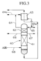
- Fig. 3 is a schematic drawing showing the main part of a third embodiment of the present invention.
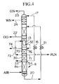
- Fig. 4 is a schematic drawing showing the main part of a fourth embodiment of the present invention.
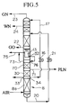
- Fig. 5 is a schematic drawing showing the main part of a modified example of the fourth embodiment of the present invention.
- Fig. 6 is a schematic drawing showing an example of a conventional air liquefaction separation installation.
- Fig. 1 shows a first embodiment of the present invention.
- An air liquefaction separation installation according to this embodiment does not have a catalytic reaction system as has the installation shown in Fig. 6, i.e., a heat exchanger 2, a heater 3, and a catalytic reaction column 4.
- the air liquefaction separation installation of this embodiment is provided with:
- a tube type or shell and coil type condenser evaporator may also be used, as well as a plate-fin type heat exchanger in main condenser evaporator which is used in this embodiment.
- Nitrogen gas withdrawn from the above-described carbon monoxide-containing nitrogen gas withdrawal part 33 is introduced into an expansion turbine 11 via a pipe 10 so as to produce cold, and thereafter, the liquefied nitrogen withdrawn from the liquefied nitrogen withdrawal part 34 is introduced into the upper part of an upper column 18 via a pressure reducing valve 16 and a pipe 17.
- Nitrogen gas withdrawn from the carbon monoxide-containing nitrogen gas withdrawal part 33 has approximately the same purity as that of nitrogen gas withdrawn from the upper part of the lower column via the pipe 9 of the above-described conventional example of. Also, liquefied nitrogen withdrawn from the liquefied nitrogen withdrawal part 34 has approximately the same purity as that of liquefied nitrogen fed into the upper column 18 of the above-described conventional example.
- liquefied nitrogen in the pipe 17, which is to flow into the upper column 18 as a reflux liquid has an oxygen concentration of no more than 100 ppm, and usually has only several parts per million, which is close to the oxygen concentration in nitrogen from the conventional installation. Therefore, product nitrogen gas having an oxygen concentration of no more than several parts per million can be obtained from a pipe 23 at the upper part of the upper column 18, in a manner similar to that of the above-described conventional example.
- the ratio of the amount of the reflux liquid which flows into the upper part of the lower column 8 to the ascending gas is adjusted to be no less than 85% (i.e., the reflux ratio is adjusted to be no less than 0.85). It is preferable that the reflux ratio be adjusted to no less than 0.9.
- the reflux ratio is adjusted within an appropriate range, taking into consideration that when the reflux ratio is brought near 1, the separation efficiency with respect to carbon monoxide is improved; however, the amount of the nitrogen gas or liquified nitrogen having a reduced amount of carbon monoxide is reduced.
- the nitrogen gas withdrawn from the carbon monoxide-containing nitrogen gas withdrawal part 33 is not essential, as long as the above-stated range of the reflux ratio is obtained.
- the carbon monoxide-containing nitrogen gas withdrawal part 33 may be installed at another location in the case where a fluid for the expansion turbine is withdrawn from another part.
- the number of theoretical plates in the carbon monoxide rectification part 30 is chosen to be no fewer than 10, and preferably no fewer than 14. It may be arbitrarily chosen whether the number of the plates of the carbon monoxide rectification part 30 should be further added to the number of plates of the conventional rectification column, or whether the upper part of the conventional rectification column should be used as the carbon monoxide rectification part 30, and this may be decided depending on the required purity of the highly pure nitrogen product desired. Although an increased number of plates will provide improved separation efficiency of carbon monoxide, the number of plates to be added is chosen by also taking into consideration the production conditions and cost of the rectification column.
- Nitrogen gas and liquified nitrogen each having a carbon monoxide concentration of no more than 0.1 ppm, can be withdrawn from the flow channels 31a and 32a, respectively, when the lower column 8 is constructed as described above.
- oxygen gas and nitrogen gas can be obtained as products from the upper column 18, in the same manner as above.
- nitrogen gas and liquified nitrogen having a reduced amount of carbon monoxide may still contain such low boiling point components.
- the low boiling point components may be separated by rectification by introducing the liquified nitrogen withdrawn from the flow channel 32a having a reduced amount of carbon monoxide into a low boiling point component separation column 40.
- the low boiling point component separation column 40 has, at the upper part of the column, a liquefied nitrogen introduction part 41 which receives liquefied nitrogen having a reduced amount of carbon monoxide, and a low boiling point component exhaust part 42, which discharges low boiling point components; and at the lower part of the column, are provided an evaporator 43, a nitrogen gas withdrawal part 44 for withdrawing nitrogen gas having reduced amounts of carbon monoxide, hydrogen and the like, and a liquefied nitrogen withdrawal part 45 for withdrawing liquefied nitrogen having a reduced amount of carbon monoxide.
- the liquefied nitrogen which contains low boiling point components, is introduced into the upper part of the low boiling point component separation column 40 as reflux liquid, and then the liqued nitrogen makes contacts with nitrogen gas ascending in the column which was evaporated by the evaporator 43.
- the low boiling point components then become concentrated in the upper part of the column.
- Feed air, liquefied air, gas in any part of the lower column 8, and oxygen gas in the upper column 18 can be used as heating gas in the evaporator 43.
- the low boiling point components concentrated in the upper part is withdrawn via a control valve 46 and a pipe 47, together with a portion of the nitrogen gas. Simultaneously, from the nitrogen gas withdrawal part 44 and the liquefied nitrogen withdrawal part 45 connected to the lower part of the column, an ultrapure nitrogen gas and an ultrapure liquefied nitrogen, from which the low boiling point components have been removed, are withdrawn, respectively.
- ultrapure nitrogen from which high boiling point components such as carbon monoxide, and low boiling point components such as hydrogen, are removed can be obtained only by the operation of rectification from the withdrawal parts 44 and 45.
- the remainder of the ascending gas (60,000 Nm 3 /h) flows upwardly in the carbon monoxide rectification part 30 so as to be rectified, and after carbon monoxide is separated and removed, the all gas is introduced into main condenser-evaporator through flow channel 31 and is liquefied by heat-exchanging with the liquefied oxygen in the lower part of the upper column 18 so as to become liquefied nitrogen containing 0.001 ppm oxygen, 0.04 ppm carbon monoxide, 100 ppm hydrogen, and 0.2 ppm argon.
- 1,670 Nm 3 /h of the liquefied nitrogen flowing into the flow channel 32a as described above is introduced as reflux liquid into the upper part of the low boiling point component separation column 40.
- 670 Nm 3 /h of nitrogen gas which contains low boiling point components is withdrawn via the low boiling point component exhaust part 42, which is connected onto the upper part of the column, and 1,000 Nm 3 /h of an ultrapure liquefied nitrogen, containing no more than 0.1 ppm carbon monoxide and no more than 0.1 ppm hydrogen, is withdrawn via the liquefied nitrogen withdrawal part 45 which is connected to the lower part of the column.
- the pressure loss of a conventional catalytic reaction system is approximately 2,000 mmAq, while that of this embodiment of the present invention (provided that the number of plates of the carbon monoxide rectification part 30 is 14) is approximately 420 mmAq. Therefore, in this embodiment of the present invention, the pressure loss may be reduced by approximately 1500 mmAq, the delivery pressure of the compressor 1 may be reduced by this amount, and accordingly, the required power may be reduced by 50-100 kW.
- Fig. 2 shows a second embodiment of the present invention, wherein the present invention is applied to an air liquefaction separation installation provided with a facility for isolating argon.
- a crude argon column 50 and a pure argon column 52 are provided.
- the crude argon column 50 is installed connectively to the upper column 18 so as to obtain crude argon.
- the argon-containing oxygen gas in the upper column 18 is used in the crude argon column 50 as a feed gas.
- the crude argon (RAr) is then withdrawn from the crude argon column 50 by a pipe 51 so that oxygen contained in the crude argon (RAr) can be removed by a separate process.
- the deoxidized argon (DAr) from which oxygen has been thus removed is then introduced into the pure argon column 52 so that liquefied highly pure argon (LAr) can be obtained.
- the above-described low boiling point component separation column 40 is provided connectively above the pure argon column 52, while the evaporator 43 at the lower part of the low boiling point component separation column 40 also serves as a condenser for the pure argon column 52.
- the gas in the pure argon column 52 can be used as a heating source for the evaporator 43 in the low boiling point component separation column 40, while the liquefied nitrogen in the lower part of the low boiling point component separation column 40 can be utilized as a cold source for the condenser.
- Fig. 3 shows a third embodiment of the present invention, wherein the present invention is applied to a single rectification column.
- the single rectification column 60 is provided with:
- both of the above-described nitrogen gas withdrawal part 66 and liquefied nitrogen withdrawal part 67 are not always necessary.
- the main product of the liquefied or gaseous nitrogen may be withdrawn from which one of the withdrawal parts 66 and 67.
- Compressed, refined, and then cooled feed air is introduced into the lower part of the single rectification column 60 via a pipe 68, and then according to a rectification action similar to that of the above-described lower column 8, nitrogen gas, having a reduced amount of carbon monoxide, is concentrated in the upper part of the column, and nitrogen gas and liquefied nitrogen having a reduced amount of carbon monoxide, are withdrawn from the flow channels 64a and 65a, respectively.
- Figs. 4 and 5 show a fourth embodiment of the present invention, wherein a carbon monoxide rectification part 30 is installed above a conventional rectification part 8a in a rectification column (lower column 8), and furthermore, a low boiling point component rectification part 70 having a number of the plates from 1 to 5, inclusive, is provided above the carbon monoxide rectification part 30.
- a nitrogen gas withdrawal part 72 for withdrawing nitrogen gas having a reduced amount of carbon monoxide is provided between the low boiling point component rectification part 70 and the carbon monoxide rectification part 30 so as to withdraw nitrogen gas therefrom and to introduce the nitrogen gas into the main condensation evaporator 13.
- nitrogen gas withdrawal part 73 is provided at the upper part of the low boiling point component rectification part 70 so as to withdraw nitrogen gas therefrom and introduce the nitrogen gas into the main condensation evaporator 13.
- nitrogen gas wherein low boiling point components are concentrated is withdrawn from a pipe 74 connected to the upper part of the low boiling point component rectification part 70 according to Fig. 4 and from a pipe 75 which branches from the entrance part of the main condensation evaporator 13 according to Fig. 5, respectively.
- the amount of the nitrogen gas containing low boiling point components is adjusted so that the amount of hydrogen in the ultrapure liquefied nitrogen withdrawn from the withdrawal part 71 is below the predetermined amount.
- the liquefied nitrogen which was liquefied by the main condenser evaporator 13 is introduced into the upper part of the low boiling point component rectification part 70, and is then used as reflux liquid in the low boiling point component rectification part 70 and the carbon monoxide rectification part 30.
- the structures of the installation for air liquefaction separation according to the present invention may be suitably arranged corresponding to the type and quantity of the products to be isolated, and they are therefore not limited to the above-described embodiments.
- the rectification column is not limited to a sieve tray column, but may be a packing column wherein regular or irregular packings are provided.
Landscapes
- Engineering & Computer Science (AREA)
- Physics & Mathematics (AREA)
- Mechanical Engineering (AREA)
- Thermal Sciences (AREA)
- General Engineering & Computer Science (AREA)
- Chemical & Material Sciences (AREA)
- Chemical Kinetics & Catalysis (AREA)
- Separation By Low-Temperature Treatments (AREA)
Description
Simultaneously, from the nitrogen
Claims (8)
- An air liquefaction separation installation which comprises a rectification column (8,60) to separate air into oxygen and nitrogen, in order to obtain ultrahigh purity nitrogen, having a condenser evaporator (13,63) thereabove and which separates at least one atmospheric constituent and nitrogen within which the amount of carbon monoxide is reduced, wherein the separation is carried out by introducing compressed, refined, and cooled feed air into said rectification column (8,60) and carrying out liquefaction rectification separation, the installation further comprising a carbon monoxide rectification part (30,62) having more than 10 theoretical plates, characterised in that the carbon monoxide rectification part is disposed in the upper part of said rectification column (8,60), and the air liquefaction separation installation also comprises :a collecting part (31a,32a,64a,65a), for withdrawing a part of nitrogen within which the amount of carbon monoxide is reduced, connected to the upper part of said carbon monoxide rectification part (30,62) and/or to said condenser evaporator (13,63) ;a carbon monoxide containing nitrogen withdrawal part (33,34,66,67), for withdrawing nitrogen containing carbon monoxide, connected to the lower part of said carbon monoxide rectification part (30,62) ;a flow channel (31,64) for introducing nitrogen gas, within which the amount of carbon monoxide is reduced, and which is withdrawn from the upper part of said carbon monoxide rectification part (30.62), into said condenser evaporator (13,63) ;a flow channel (32,65) for carrying most nitrogen liquefied by said condenser-evaporator (13,63) to the upper part of said rectification column (8,60) as a reflux liquid for said rectification column (8,60) ;and in addition to said rectification column (8,60), a low boiling point component separation column (40) comprising ;a liquefied nitrogen introduction part (41) for introducing, as a reflux liquid, the remaining portion of the nitrogen within which the amount of carbon monoxide is reduced, and which is liquefied by said condenser-evaporator (13,63) and withdrawn as liquefied nitrogen from said collecting part (32a,65a), into said low boiling point rectification column (40) ;a low boiling point component exhaust part (42) for withdrawing nitrogen gas containing low boiling point components ; said liquefied nitrogen introduction part (41) and said low boiling point component exhaust part (42) connected to the upper part of said low boiling point component separation column (40) ;an evaporator (43) disposed in a lower part of said low boiling point component separation column ; andan ultrapure nitrogen gas withdrawal part (44) and an ultrapure liquefied nitrogen withdrawal part (45), both disposed in the lower part of said low boiling point component rectification column (40), from which ultrapure nitrogen gas and ultrapure liquid nitrogen are withdrawn respectively.
- An air liquefaction separation installation according to Claim 1, wherein said rectification column is a lower column (8) of a double rectification column.
- An air liquefaction separation installation according to Claim 1, wherein said rectification column is a single rectification column (60).
- An air liquefaction separation installation according to Claim 1, wherein said air liquefaction separation installation further comprises a pure argon column (52) which is provided connectively to said low boiling point component separation column (40), whereby said evaporator (43) is also used as a condenser for said pure argon column (52).
- An air liquefaction separation installation which comprises a rectification column (8) to separate air into oxygen and nitrogen, in order to obtain ultrahigh purity nitrogen, having a condenser evaporator (13) thereabove and which separates at least one atmospheric constituent and nitrogen within which the amount of carbon monoxide is reduced, wherein the separation is carried out by introducing compressed, refined, and cooled feed air into said rectification column (8) and carrying out liquefaction rectification separation, the installation also comprising a carbon monoxide rectification part (30) having more than 10 theoretical plates, characterised in that the carbon monoxide rectification part (30) is disposed in the upper part of said rectification column (8), and said air liquefaction separation installation also comprises :a collecting part (31a,32a), for withdrawing a part of nitrogen within which the amount of carbon monoxide is reduced, connected to the upper part of said carbon monoxide rectification part (30) and/or to said condenser evaporator (13) ;a carbon monoxide containing nitrogen withdrawal part (33,34), for withdrawing nitrogen containing carbon monoxide, connected to the lower part of said carbon monoxide rectification part (30) ;a flow channel (72) for introducing nitrogen gas, within which the amount of carbon monoxide is reduced, and which is withdrawn from the upper part of said carbon monoxide rectification part (30), into said condenser evaporator (13);a flow channel (32) for carrying most nitrogen liquefied by said condenser evaporator (13) to the upper part of said rectification column (8) as a reflux liquid for said rectification column (8);a low boiling point component rectification part (70) above said carbon monoxide rectification part (30) in the upper part of said rectification column (8) ;a withdrawal part (71), for withdrawing nitrogen within which the amount of carbon monoxide and low boiling point components are reduced, disposed between said low boiling point component rectification part (70) and said carbon monoxide rectification part (30) ; anda withdrawal part (74,75) for withdrawing nitrogen gas which contains low boiling point components, and an introduction part (76) for introducing liquefied nitrogen which is liquefied in said condenser evaporator (13), both connected to the upper part of said low boiling point component rectification part (70) ;wherein ultrapure nitrogen is withdrawn via the withdrawal part (71) between said low boiling point component rectification part (70) and said carbon monoxide rectification part (30).
- An air liquefaction separation installation according to claim 5, wherein said air liquefaction separation installation further comprises :a flow channel (73) which is substituted for the flow channel (72), for withdrawing nitrogen gas from the upper part of said low boiling point component rectification part (70) and for introducing said nitrogen gas into said condenser (13).
- An air liquefaction separation installation according to claim 5, wherein said low boiling point component rectification part (70) has from 1 to 5 theoretical plates.
- An air liquefaction separation process for producing ultra-high purity nitrogen from air by isolating products of at least one atmospheric constituent and nitrogen within which the amount of carbon monoxide is reduced, whereby compressed, refined, and then cooled feed air is introduced into a rectification column (8,60) which separates air into oxygen and nitrogen, and which comprises a condenser evaporator (13,63) in the upper part of said rectification column (8,60) so as to carry out liquefaction rectification separation, said air liquefaction separation process being characterized by :using a carbon monoxide rectification part (30,62) which is provided in the upper part of said rectification column (8,60), wherein said carbon monoxide rectification part (30,62) has more than 10 theoretical plates, said air liquefaction separation process being further characterized by the steps comprising :withdrawing nitrogen gas, within which the amount of carbon monoxide is reduced, and which contains most ascending gas from a conventional rectification part (8a,61) provided in the lower portion of said rectification column (8,60) from the upper portion of said carbon monoxide rectification part (30,62);introducing said nitrogen, within which the amount of carbon monoxide is reduced, into said condenser evaporator (13,63) to produce liquefied nitrogen;introducing most of said liquefied nitrogen to the upper part of said rectification column (8,60) as a reflux liquid for said rectification column (8,60);carrying out rectification so that the reflux ratio at said carbon monoxide rectification part (30,62) is no less than 0.85; and withdrawing nitrogen having reduced amount of carbon monoxide from the upper part of said rectification column (8,60) or from said condenser evaporator (13,63) ;withdrawing nitrogen containing carbon monoxide from the lower portion (10,34,66,67) of said carbon monoxide rectification part (30,62), while adjusting the total amount of nitrogen, having a reduced amount of carbon monoxide, and withdrawn from the upper portion of said carbon monoxide rectification part (30,62), to not more than 15% of the amount of the ascending gas in said carbon monoxide rectification part (30,62) ;wherein the remaining liquid portion of said liquid nitrogen is introduced into a low boiling point component rectification part, and ultrapure nitrogen is withdrawn from the lower part of said low boiling point component rectification part, or the remaining liquid portion of said liquid nitrogen is introduced into a low boiling point rectification part above said carbon monoxide rectification part in the upper part of said rectification column, and ultrapure nitrogen is withdrawn between said low boiling point component rectification part and said carbon monoxide rectification part.
Applications Claiming Priority (2)
| Application Number | Priority Date | Filing Date | Title |
|---|---|---|---|
| JP116186/92 | 1992-05-08 | ||
| JP11618692A JP3306517B2 (en) | 1992-05-08 | 1992-05-08 | Air liquefaction separation apparatus and method |
Publications (2)
| Publication Number | Publication Date |
|---|---|
| EP0569310A1 EP0569310A1 (en) | 1993-11-10 |
| EP0569310B1 true EP0569310B1 (en) | 1998-06-03 |
Family
ID=14680952
Family Applications (1)
| Application Number | Title | Priority Date | Filing Date |
|---|---|---|---|
| EP93420186A Expired - Lifetime EP0569310B1 (en) | 1992-05-08 | 1993-05-07 | Installation for air liquefaction separation and process therefor |
Country Status (4)
| Country | Link |
|---|---|
| US (1) | US5359857A (en) |
| EP (1) | EP0569310B1 (en) |
| JP (1) | JP3306517B2 (en) |
| DE (1) | DE69318886D1 (en) |
Families Citing this family (11)
| Publication number | Priority date | Publication date | Assignee | Title |
|---|---|---|---|---|
| US5351492A (en) * | 1992-09-23 | 1994-10-04 | Air Products And Chemicals, Inc. | Distillation strategies for the production of carbon monoxide-free nitrogen |
| US5461872A (en) * | 1994-11-21 | 1995-10-31 | The Boc Group, Inc. | Air separation method and apparatus |
| US5596883A (en) * | 1995-10-03 | 1997-01-28 | Air Products And Chemicals, Inc. | Light component stripping in plate-fin heat exchangers |
| US5664438A (en) * | 1996-08-13 | 1997-09-09 | Praxair Technology, Inc. | Cryogenic side column rectification system for producing low purity oxygen and high purity nitrogen |
| GB9800693D0 (en) * | 1998-01-13 | 1998-03-11 | Air Prod & Chem | Separation of carbon monoxide from nitrogen-contaminated gaseous mixtures |
| GB9800692D0 (en) * | 1998-01-13 | 1998-03-11 | Air Prod & Chem | Separation of carbon monoxide from nitrogen-contaminated gaseous mixtures also containing hydrogen and methane |
| DE19929798A1 (en) | 1998-11-11 | 2000-05-25 | Linde Ag | Production of ultrapure nitrogen includes drawing oxygen-free pressurized nitrogen fraction from an upper portion of the pressure column liquid and releasing in the low pressure column |
| DE69907616T2 (en) * | 1998-12-28 | 2004-03-11 | Nippon Sanso Corp. | Vapor-liquid contactor, cryogenic air separation unit and process for gas separation |
| WO2003025344A1 (en) * | 2001-09-20 | 2003-03-27 | Gregory Orme | Construction methods in space |
| US8640495B2 (en) * | 2009-03-03 | 2014-02-04 | Ait Products and Chemicals, Inc. | Separation of carbon monoxide from gaseous mixtures containing carbon monoxide |
| JP7133735B1 (en) * | 2022-03-07 | 2022-09-08 | レール・リキード-ソシエテ・アノニム・プール・レテュード・エ・レクスプロワタシオン・デ・プロセデ・ジョルジュ・クロード | air separator |
Family Cites Families (14)
| Publication number | Priority date | Publication date | Assignee | Title |
|---|---|---|---|---|
| JPS61123389A (en) * | 1984-11-20 | 1986-06-11 | Matsushita Electric Ind Co Ltd | Pamametric speaker |
| JPS61225568A (en) * | 1985-03-29 | 1986-10-07 | 株式会社日立製作所 | air separation equipment |
| JPH0633934B2 (en) * | 1985-04-02 | 1994-05-02 | 大同ほくさん株式会社 | Air separation device |
| JPS62141485A (en) * | 1985-12-16 | 1987-06-24 | 日本酸素株式会社 | Manufacture of nitrogen having high purity |
| DE3610973A1 (en) * | 1986-04-02 | 1987-10-08 | Linde Ag | METHOD AND DEVICE FOR PRODUCING NITROGEN |
| US4872893A (en) * | 1988-10-06 | 1989-10-10 | Air Products And Chemicals, Inc. | Process for the production of high pressure nitrogen |
| GB8828133D0 (en) * | 1988-12-02 | 1989-01-05 | Boc Group Plc | Air separation |
| DE4017410A1 (en) * | 1989-06-02 | 1990-12-06 | Hitachi Ltd | METHOD AND DEVICE FOR PRODUCING EXTREMELY PURE NITROGEN |
| JPH04121575A (en) * | 1989-06-02 | 1992-04-22 | Hitachi Ltd | Method and apparatus for manufacturing ultrahigh purity nitrogen |
| JPH0412391A (en) * | 1990-05-01 | 1992-01-16 | Konratsukusu Matsumoto:Kk | Display device |
| US5129932A (en) * | 1990-06-12 | 1992-07-14 | Air Products And Chemicals, Inc. | Cryogenic process for the separation of air to produce moderate pressure nitrogen |
| US5137559A (en) * | 1990-08-06 | 1992-08-11 | Air Products And Chemicals, Inc. | Production of nitrogen free of light impurities |
| CA2048146C (en) * | 1990-08-06 | 1994-05-17 | Rakesh Agrawal | Production of nitrogen free of light impurities |
| US5123947A (en) * | 1991-01-03 | 1992-06-23 | Air Products And Chemicals, Inc. | Cryogenic process for the separation of air to produce ultra high purity nitrogen |
-
1992
- 1992-05-08 JP JP11618692A patent/JP3306517B2/en not_active Expired - Lifetime
-
1993
- 1993-05-07 DE DE69318886T patent/DE69318886D1/en not_active Expired - Lifetime
- 1993-05-07 EP EP93420186A patent/EP0569310B1/en not_active Expired - Lifetime
- 1993-05-10 US US08/060,017 patent/US5359857A/en not_active Expired - Lifetime
Also Published As
| Publication number | Publication date |
|---|---|
| DE69318886D1 (en) | 1998-07-09 |
| US5359857A (en) | 1994-11-01 |
| JPH05312469A (en) | 1993-11-22 |
| JP3306517B2 (en) | 2002-07-24 |
| EP0569310A1 (en) | 1993-11-10 |
Similar Documents
| Publication | Publication Date | Title |
|---|---|---|
| US5146756A (en) | Air separation | |
| EP0589646B1 (en) | Distillation process for the production of carbon monoxide-free nitrogen | |
| EP0444422A1 (en) | Production of high purity argon | |
| EP0384688B2 (en) | Air separation | |
| US5359857A (en) | Installation for air liquefaction separation and process therefor | |
| JPS6146747B2 (en) | ||
| JP2597521B2 (en) | Air separation by cryogenic distillation for crude argon product production | |
| US5106398A (en) | Air separation | |
| EP0798524B1 (en) | Ultra high purity nitrogen and oxygen generator unit | |
| US5440885A (en) | Process and installation for the production of ultra-pure nitrogen by distillation of air | |
| CA2058779C (en) | Crude neon production system | |
| EP0754923A2 (en) | Ultra-high purity nitrogen generating method and unit | |
| JPS6158747B2 (en) | ||
| HU209266B (en) | Process and equipment for generating nitrogen | |
| JPH07133982A (en) | Method and apparatus for producing high-purity argon | |
| JP3364724B2 (en) | Method and apparatus for separating high purity argon | |
| KR100319440B1 (en) | Device and method for producing low purity oxygen and high purity nitrogen | |
| JP2917031B2 (en) | Oxygen production method | |
| JP3424101B2 (en) | High purity argon separation equipment | |
| JP3082092B2 (en) | Oxygen purification method and apparatus | |
| JPH07127971A (en) | Argon separator | |
| JP3282040B2 (en) | Ultra high purity oxygen sampling method and apparatus | |
| JPS62155486A (en) | Air separation method | |
| JPH0486474A (en) | Method and device for refining nitrogen | |
| JPH0418223B2 (en) |
Legal Events
| Date | Code | Title | Description |
|---|---|---|---|
| PUAI | Public reference made under article 153(3) epc to a published international application that has entered the european phase |
Free format text: ORIGINAL CODE: 0009012 |
|
| AK | Designated contracting states |
Kind code of ref document: A1 Designated state(s): DE FR GB NL |
|
| 17P | Request for examination filed |
Effective date: 19940422 |
|
| 17Q | First examination report despatched |
Effective date: 19950720 |
|
| GRAG | Despatch of communication of intention to grant |
Free format text: ORIGINAL CODE: EPIDOS AGRA |
|
| GRAG | Despatch of communication of intention to grant |
Free format text: ORIGINAL CODE: EPIDOS AGRA |
|
| GRAG | Despatch of communication of intention to grant |
Free format text: ORIGINAL CODE: EPIDOS AGRA |
|
| GRAH | Despatch of communication of intention to grant a patent |
Free format text: ORIGINAL CODE: EPIDOS IGRA |
|
| GRAH | Despatch of communication of intention to grant a patent |
Free format text: ORIGINAL CODE: EPIDOS IGRA |
|
| GRAA | (expected) grant |
Free format text: ORIGINAL CODE: 0009210 |
|
| AK | Designated contracting states |
Kind code of ref document: B1 Designated state(s): DE FR GB NL |
|
| PG25 | Lapsed in a contracting state [announced via postgrant information from national office to epo] |
Ref country code: NL Free format text: LAPSE BECAUSE OF FAILURE TO SUBMIT A TRANSLATION OF THE DESCRIPTION OR TO PAY THE FEE WITHIN THE PRESCRIBED TIME-LIMIT Effective date: 19980603 Ref country code: FR Free format text: LAPSE BECAUSE OF FAILURE TO SUBMIT A TRANSLATION OF THE DESCRIPTION OR TO PAY THE FEE WITHIN THE PRESCRIBED TIME-LIMIT Effective date: 19980603 |
|
| REF | Corresponds to: |
Ref document number: 69318886 Country of ref document: DE Date of ref document: 19980709 |
|
| PG25 | Lapsed in a contracting state [announced via postgrant information from national office to epo] |
Ref country code: DE Free format text: LAPSE BECAUSE OF FAILURE TO SUBMIT A TRANSLATION OF THE DESCRIPTION OR TO PAY THE FEE WITHIN THE PRESCRIBED TIME-LIMIT Effective date: 19980904 |
|
| EN | Fr: translation not filed | ||
| NLV1 | Nl: lapsed or annulled due to failure to fulfill the requirements of art. 29p and 29m of the patents act | ||
| PLBE | No opposition filed within time limit |
Free format text: ORIGINAL CODE: 0009261 |
|
| STAA | Information on the status of an ep patent application or granted ep patent |
Free format text: STATUS: NO OPPOSITION FILED WITHIN TIME LIMIT |
|
| 26N | No opposition filed | ||
| REG | Reference to a national code |
Ref country code: GB Ref legal event code: IF02 |
|
| PGFP | Annual fee paid to national office [announced via postgrant information from national office to epo] |
Ref country code: GB Payment date: 20120522 Year of fee payment: 20 |
|
| REG | Reference to a national code |
Ref country code: GB Ref legal event code: PE20 Expiry date: 20130506 |
|
| PG25 | Lapsed in a contracting state [announced via postgrant information from national office to epo] |
Ref country code: GB Free format text: LAPSE BECAUSE OF EXPIRATION OF PROTECTION Effective date: 20130506 |