EP0567962B1 - Système de contrÔle pour pompe seringue - Google Patents
Système de contrÔle pour pompe seringue Download PDFInfo
- Publication number
- EP0567962B1 EP0567962B1 EP93106716A EP93106716A EP0567962B1 EP 0567962 B1 EP0567962 B1 EP 0567962B1 EP 93106716 A EP93106716 A EP 93106716A EP 93106716 A EP93106716 A EP 93106716A EP 0567962 B1 EP0567962 B1 EP 0567962B1
- Authority
- EP
- European Patent Office
- Prior art keywords
- syringe
- camming surface
- pusher
- drive
- engagement
- Prior art date
- Legal status (The legal status is an assumption and is not a legal conclusion. Google has not performed a legal analysis and makes no representation as to the accuracy of the status listed.)
- Expired - Lifetime
Links
Images


Classifications
-
- A—HUMAN NECESSITIES
- A61—MEDICAL OR VETERINARY SCIENCE; HYGIENE
- A61M—DEVICES FOR INTRODUCING MEDIA INTO, OR ONTO, THE BODY; DEVICES FOR TRANSDUCING BODY MEDIA OR FOR TAKING MEDIA FROM THE BODY; DEVICES FOR PRODUCING OR ENDING SLEEP OR STUPOR
- A61M5/00—Devices for bringing media into the body in a subcutaneous, intra-vascular or intramuscular way; Accessories therefor, e.g. filling or cleaning devices, arm-rests
- A61M5/14—Infusion devices, e.g. infusing by gravity; Blood infusion; Accessories therefor
- A61M5/142—Pressure infusion, e.g. using pumps
- A61M5/145—Pressure infusion, e.g. using pumps using pressurised reservoirs, e.g. pressurised by means of pistons
- A61M5/1452—Pressure infusion, e.g. using pumps using pressurised reservoirs, e.g. pressurised by means of pistons pressurised by means of pistons
- A61M5/1456—Pressure infusion, e.g. using pumps using pressurised reservoirs, e.g. pressurised by means of pistons pressurised by means of pistons with a replaceable reservoir comprising a piston rod to be moved into the reservoir, e.g. the piston rod is part of the removable reservoir
-
- A—HUMAN NECESSITIES
- A61—MEDICAL OR VETERINARY SCIENCE; HYGIENE
- A61M—DEVICES FOR INTRODUCING MEDIA INTO, OR ONTO, THE BODY; DEVICES FOR TRANSDUCING BODY MEDIA OR FOR TAKING MEDIA FROM THE BODY; DEVICES FOR PRODUCING OR ENDING SLEEP OR STUPOR
- A61M5/00—Devices for bringing media into the body in a subcutaneous, intra-vascular or intramuscular way; Accessories therefor, e.g. filling or cleaning devices, arm-rests
- A61M5/14—Infusion devices, e.g. infusing by gravity; Blood infusion; Accessories therefor
- A61M5/142—Pressure infusion, e.g. using pumps
- A61M5/145—Pressure infusion, e.g. using pumps using pressurised reservoirs, e.g. pressurised by means of pistons
- A61M5/1452—Pressure infusion, e.g. using pumps using pressurised reservoirs, e.g. pressurised by means of pistons pressurised by means of pistons
- A61M2005/14573—Pressure infusion, e.g. using pumps using pressurised reservoirs, e.g. pressurised by means of pistons pressurised by means of pistons with a replaceable reservoir for quick connection/disconnection with a driving system
-
- A—HUMAN NECESSITIES
- A61—MEDICAL OR VETERINARY SCIENCE; HYGIENE
- A61M—DEVICES FOR INTRODUCING MEDIA INTO, OR ONTO, THE BODY; DEVICES FOR TRANSDUCING BODY MEDIA OR FOR TAKING MEDIA FROM THE BODY; DEVICES FOR PRODUCING OR ENDING SLEEP OR STUPOR
- A61M2205/00—General characteristics of the apparatus
- A61M2205/60—General characteristics of the apparatus with identification means
- A61M2205/6036—General characteristics of the apparatus with identification means characterised by physical shape, e.g. array of activating switches
-
- A—HUMAN NECESSITIES
- A61—MEDICAL OR VETERINARY SCIENCE; HYGIENE
- A61M—DEVICES FOR INTRODUCING MEDIA INTO, OR ONTO, THE BODY; DEVICES FOR TRANSDUCING BODY MEDIA OR FOR TAKING MEDIA FROM THE BODY; DEVICES FOR PRODUCING OR ENDING SLEEP OR STUPOR
- A61M5/00—Devices for bringing media into the body in a subcutaneous, intra-vascular or intramuscular way; Accessories therefor, e.g. filling or cleaning devices, arm-rests
- A61M5/14—Infusion devices, e.g. infusing by gravity; Blood infusion; Accessories therefor
- A61M5/142—Pressure infusion, e.g. using pumps
- A61M5/145—Pressure infusion, e.g. using pumps using pressurised reservoirs, e.g. pressurised by means of pistons
- A61M5/1452—Pressure infusion, e.g. using pumps using pressurised reservoirs, e.g. pressurised by means of pistons pressurised by means of pistons
- A61M5/1458—Means for capture of the plunger flange
-
- Y—GENERAL TAGGING OF NEW TECHNOLOGICAL DEVELOPMENTS; GENERAL TAGGING OF CROSS-SECTIONAL TECHNOLOGIES SPANNING OVER SEVERAL SECTIONS OF THE IPC; TECHNICAL SUBJECTS COVERED BY FORMER USPC CROSS-REFERENCE ART COLLECTIONS [XRACs] AND DIGESTS
- Y10—TECHNICAL SUBJECTS COVERED BY FORMER USPC
- Y10S—TECHNICAL SUBJECTS COVERED BY FORMER USPC CROSS-REFERENCE ART COLLECTIONS [XRACs] AND DIGESTS
- Y10S128/00—Surgery
- Y10S128/01—Motorized syringe
Definitions
- the invention lies in the field of infusion pumps for dispensing fluid from syringes.
- it relates to the control of the syringe holding and syringe plunger drive mechanisms of an infusion pump of the kind called for in the preamble of Claim 1, which is known, e.g. from BE-A-904 426.
- Infusion pumps are frequently employed in the medical field for administering medications of various types. Such pumps are often designed to accommodate a pre-filled syringe as witnessed, e.g. by US-A-3 858 581.
- the syringe is usually held in place by a clamping mechanism.
- the medication is expelled from the syringe by means of a motor driven pusher which pushes the plunger of the syringe.
- an infusion pump for pumping fluid from a syringe therefore typically comprises the following elements: means to hold the syringe in place for pumping; pusher means for pushing the plunger of the syringe during pumping; and drive means such as a motor for driving the pusher means.
- Typical syringe pumps of the prior art have separate controls for securing the syringe for pumping and for engaging the drive mechanism.
- placing or removing the syringe and starting or stopping the infusion process required the use of both of the hands of the operator and made these operations somewhat cumbersome.
- steps (1), (5), and (6) were all performed by separate mechanisms having separate controls often inconveniently spaced apart from each other at various positions on the syringe pump.
- the present invention enables steps (4), (5) and (6) to be performed by adjusting a single control or controls which are conveniently close to each other.
- the syringe pump of the invention which has the further features set forth in Claim 1, comprises a control system which permits several important operations to be performed single handed using a single control or controls conveniently located near each other on a control panel.
- the syringe pump has a lockable clamp for holding the syringe in place for pumping. It also has a pusher for pushing the plunger of the syringe to expel fluid from the syringe and a drive mechanism for driving the pusher.
- a single control knob engages and disengages the drive mechanism and locks and unlocks the syringe clamp.
- the control may be in one of at least two positions.
- the syringe holder When the control is in a first position the syringe holder is unlocked and the pusher can move freely.
- the drive mechanism is disengaged and the syringe can be placed in the pump and the pusher can be moved into position to abut the plunger. This allows the pusher to be correctly positioned relative to the syringe and the holder.
- the control is moved into a second position, the syringe holder tightly closes on the syringe, holding it in place and the drive mechanism is engaged. The pusher cannot readily be moved independently of the drive mechanism and the pump is ready for use.
- the control can then be moved into a third position in which the motor is activated and the pusher depresses the syringe plunger.
- the control knob can be moved back to the first position for removal of the syringe, adjustment of the pusher or administration of a bolus dose. This can be done by means of a single control on the pump housing.
- an infusion pump 10 is provided for causing fluid to be pumped from a syringe.
- a pump of this general type is disclosed in U.S. Patent No. 4,838,857, which is incorporated by reference herein.
- Such pumps are frequently employed for administering drugs such as antibiotics over a time. They are preferably capable of accepting several sizes of syringes.
- Housing 12 which is made from a durable, light-weight material.
- Housing 12 comprises a base 12A, a mid-housing 12B, a battery compartment cover 12C and a drive mechanism compartment cover 12D.
- An integral handle 14, which may also function as a battery compartment, is defined by one portion of the housing.
- a recess 16 is defined by handle 14, drive mechanism compartment 18, and a portion of base 12A.
- Recess 16 includes an elongate opening 20 which facilitates use of handle 14.
- a syringe pusher 22 is also positioned within recess 16. Syringe pusher 22 is adapted for engaging the flanged end of a syringe plunger and moving the plunger within the barrel of a syringe. The operation of the pusher is described in greater detail below.
- the recess has an elongated configuration of suitable length and width for accommodating a variety of syringe sizes.
- a pair of control knobs is provided on the front face of the housing.
- a first knob 26 is used for controlling the pump driving mechanism and a syringe clamp to hold the syringe in place during pumping, both of which are discussed below.
- a second knob 28 is used to lock and unlock a pole clamp 30, as shown in Fig. 2.
- Pole clamp 30 is used for securing the pump to an I.V. pole or a rail (not shown).
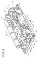
- a belt/pulley drive mechanism 23 is employed for driving syringe pusher 22.
- the drive mechanism 23 includes gear assembly 40 and a d.c. motor 34 including an integral reduction assembly. While a stepper motor could alternatively be employed, a d.c. motor is preferred as it requires less power and is controllable in a less expensive and complex manner than a stepper motor.
- Motor 34 is powered by an appropriate power source such as the four batteries 36 shown in Figs. 3 and 4.
- the motor may have an integral reduction gear assembly which drives pinion 38.
- the output shaft of the motor includes pinion 38 which is engageable with a gear reduction assembly 40 which provides a substantial overall gear reduction. A reduction on the order of about 15,000:1 is provided by the combined operations of the integral reduction assembly of motor 34 and gear reduction assembly 40.
- Gear 42 nearest to pinion 38 is mounted to a cradle 44, as shown in Figs. 5A, 5B, 6, 9A and 9B.
- Cradle 44 is pivotably secured to a disengage link 46, which is shown in detail in Fig. 8.
- a peg 48 extending from cradle 44 is positioned within a slotted opening 50 within disengage link 46.
- a first set of opposing openings 52A, 52B within cradle 44 receives shaft 54 about which gear 42 rotates.
- a second set of openings 56A, 56B allows cradle 44 to be pivotably secured by pin 47 to a projection 58 extending from base 12A. Longitudinal movement of disengage link 46 accordingly causes cradle 44 to pivot about an axis extending through pin 47.
- Cradle 44 and disengage link 46 and their associated shafts, pins, springs and accessories are collectively referred to as "engagement means.”
- Disengage link 46 is positioned between projection 58 and a wall 60 which extends from base 12A.
- the end of disengage link 46 opposite from slotted opening 50 includes a laterally extending wall 62 having a rounded projection 64 extending from an edge portion thereof (See Fig. 6 which shows wall 60 and part of disengage link 46 cut away for clarity).
- Camming projection 64 is engageable with either of two notches formed in a wall 66 extending radially from shaft 68 of the control knob 26, depending upon the rotational position of control knob 26.
- disengage link 46 is urged in the direction of pinion 38 by a coil spring 70.
- cradle 44 When projection 64 is not positioned within one of the notches of wall 66, cradle 44 is in a generally upright position and gear 42 is disengaged from pinion 38.
- Rotation of control knob 26 to a position where projection 64 moves into the notches of wall 66 causes the movement of disengage link 46 away from pinion 38.
- Cradle 44 accordingly rotates about pin 47, causing gear 42 to engage pinion 38.
- FIG. 5B which shows wall 60 removed and part of disengage link 46 cut away for clarity.
- the drive mechanism for the pump includes an endless belt 72 which is supported by a drive pulley 74 and an idler pulley 76. Both pulleys are supported by the walls of base 12A.
- Drive pulley 74 is engaged with gear reduction assembly 40 and driven thereby.
- Syringe pusher 22 is secured to belt 72.
- first knob 26 controls the engagement and disengagement of pinion 38 and gear 42.
- syringe pusher 22 can only be moved upon rotation of pinion 38.
- Neither syringe pusher 22 nor belt 72 can be moved manually at this time.
- syringe pusher 22 can be moved manually to a selected position as gear reduction assembly 40 provides little frictional resistance to rotation of belt 72. This allows pusher 22 to be moved within recess 20 with little resistance. A syringe can thus be easily positioned within recess 16 without obstruction.
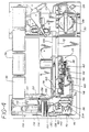
- a clamp assembly 128 for clamping a syringe barrel is shown.
- such assemblies have generally included heavy springs to maintain a syringe in place. Because the user must open the clamp assembly to insert or remove a syringe, the force exerted by the spring must be limited to permit ease of use. Lower spring forces do not, however, provide effective holding capability.
- An alternative syringe clamp of the prior art includes a clamp operated by a screw. Such a device is cumbersome and it takes a long time to open and close such a clamp. Existing assemblies accordingly involve compromises due to these contradictory objectives.
- the clamp assembly 128 in accordance with the invention provides both security and ease of use without compromising either feature. It includes a locking mechanism comprising a toothed member 130 which is pivotably secured to base 12A, a spring 132 for resiliently urging toothed member 130 about an axis of rotation, a clamping slide 134 for engaging a syringe barrel, and a spring 136 for resiliently urging the slide in a selected direction.
- Toothed member 130 preferably includes a toothed surface 138, as best shown in Fig. 4. This surface is located in opposing relation to a toothed surface 140 of clamping slide 134. Toothed member 130 is pivotable about a pin 142 such that the toothed surface of toothed member 130 is movable into and out of engagement with the toothed surface of the slide. Spring 132 urges the toothed member out of engagement with clamping slide 134.
- shaft 68 of control knob 26 includes a flat longitudinal surface 144 at the bottom thereof, the remainder of shaft 68 being a substantially cylindrical camming surface 145.
- Toothed member 130 includes an arm 146 which adjoins the bottom portion of shaft 68. The rotational position of flat surface 144 determines whether arm 146 engages the flat or cylindrical surface of shaft 68. If flat surface 144 is moved into opposing relation with arm 146, spring 132 causes toothed member 130 to move out of engagement with slide 134. Rotation of shaft 68 causes the cylindrical surface to engage arm 146, thereby rotating toothed member 130 about pin 142 and into engagement with slide 134.
- Slide 134 houses spring 136 which causes it to move into engagement with a syringe barrel.
- Spring 136 extends between a projection 148 extending from base 12A and an inner wall of slide 134.
- Slide 134 includes a face portion 150 having an arcuate surface for accommodating a syringe barrel. Face portion 150 extends vertically with respect to base 12A and is positioned within recess 16.
- wall 66, flat portion 144 and camming surface 145 of shaft 68 determine the order of the engagement of gear 42 with pinion 38 and toothed member 130 with toothed surface 140.
- Wall 66, flat portion 144 and camming surface 145 can be oriented such that (1) gear 42 and pinion 38 mesh simultaneously with each other when flat portion 144 causes toothed member 130 to engage with toothed surface 140; (2) gear 42 and pinion 38 mesh only once toothed member 130 and toothed surface 140 engage or (3) gear 42 and pinion 38 mesh before toothed member 130 and toothed surface 140 engage.
- Wall 66, flat portion 144 and camming surface 145 can also be oriented so that gear 42 and pinion 38 can be engaged and disengaged while toothed member 130 and toothed surface 140 remain engaged.
- the preferred embodiment option (1) is described herein with the understanding that a person of ordinary skill in the art would easily be able to modify the device to accomplish options (2) and (3).
- control knob 26 Before or after securing the pump 10 to the pole, control knob 26 is turned to a "release" position if not already in such a position.
- a filled syringe is positioned in recess 16 of the pump housing such that the flange of the syringe barrel extends within slot 152.
- Syringe pusher 22 is then manually engaged and moved into position against the flanged end of the syringe plunger. The flange of the syringe plunger is clamped between lip 82 of the swing arm 80 and one of the projections 94, 96 extending from bottom wall 98 of the pusher housing.
- the on-off switch for the motor is, of course, in the "off" mode at this time due to the position of motor on/or switch 214 with respect to a switch actuating peg 216 which extends radially from the shaft of control knob 26.
- On-off switch 214 is shown as actuated by control knob 26, but can of course be actuated by a separate control.
- Control knob 26 may be turned to a second detent (run) position wherein rounded projection 64 moves within the second notch of wall 66 extending radially from control knob shaft 68.
- the positions of disengage link 46 and toothed member 130 are the same whether control knob 26 is in the "motor off” or “motor run” position.
- peg 216 extending from the shaft 68 of control knob 26 engages motor on/off switch 214, thereby causing motor 34 to operate.
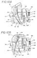
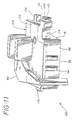
- Syringe pusher 22 is shown in greatest detail in Figs. 10A, 10B and 11.
- Fig. 10B shows pusher 22 as positioned when engaging the flanged end of a syringe plunger while Fig. 10A shows it in the fully closed position where no plunger would be engaged.
- Syringe pusher 22 includes a housing 78 to which a swing arm 80 is pivotably mounted.
- Swing arm 80 includes a lip 82 suitable for engaging the flange of a syringe plunger.
- a spring 84 is secured to a peg 86 extending from the opposite end of swing arm 80, and urges it towards the position shown in Fig. 10A.
- a first switch 88 is mounted to housing 78 for detecting the position of swing arm 80. Different signals are accordingly provided depending upon whether arm 80 is in the position shown in Fig. 10A or Fig. 10B. The presence or absence of a syringe may accordingly be detected.
- the user will be alerted as to whether the syringe plunger flange is properly engaged.
- the latter feature is important in that swing arm 80 provides anti-siphon protection. In other words, the syringe plunger cannot be moved on its own while clamped to syringe pusher 22 and while motor pinion 38 is engaged as described above.
- a lever 90 is also pivotably mounted to syringe pusher housing 78.
- Lever 90 is positioned adjacent to a second switch 92 which provides a signal when an occlusion is detected or when the syringe plunger has reached the end of the bottom of the syringe barrel.
- a cover 93 is secured to housing 78 for protecting lever 90 and switches 88, 92.
- a pair of projections 94, 96 is secured to lever 90 and extends through a pair of openings in bottom wall 98 of housing 78.
- First projection 94 is longer than second projection 96 and is positioned closer to pivot 100 about which lever 90 rotates.
- a spring 102 resiliently urges lever 90 towards bottom wall 98 of housing 78. It will be appreciated that a greater force is required to move lever 90 when first projection 94 is used to apply a force to it than when the second projection 96 is so employed.
- the projections are accordingly positioned such that the flanged end of a relatively large syringe mounted to the pump will engage first projection 94 while the flanged end of a relatively small syringe will engage second projection 96.
- a greater force is accordingly required to actuate switch 92 when a large syringe is in place than when a small syringe is employed. This is desirable as a greater force is required to drive the plunger of a large syringe than a small syringe under normal operating conditions. A correspondingly larger force should be necessary to generate an occlusion signal when a large syringe is being emptied than when a small syringe is emptied.
- a connecting member 104 extends from housing 78.
- Connecting member 104 includes three projections 106, 108, 110.
- Belt 72 is positioned between projections 106, 108, 110 such that the toothed surface thereof engages a toothed surface 112 of lower projection 110.
- Connecting member 104 extends through an elongate slot 113 (Fig. 1) in housing 12 which adjoins recess 16 in which a syringe may be positioned.
- a channel 114 is defined by the connecting member. The channel receives the upper edge of a wall of the mid-housing 12B.
- the opposite end of the syringe pusher 22 includes a projection 116 which rides upon another upper edge of the mid-housing 12B.
- a relatively narrow, elongate slot 118 is defined within handle 14 for receiving projection 116.
- Syringe pusher 22 is accordingly supported at both ends by mid-housing 12B.
- a resilient, semi-rigid, elongate band 120 is provided for covering slot 113.
- Band 120 is preferably opaque, and includes a plurality of openings 122 extending through at least a portion thereof.
- Band 120 is sufficient in length and width to cover the entire slot regardless of the position of syringe pusher 22.
- a rectangular notch 124 is provided within the band for receiving connecting member 104 of syringe pusher 22.
- Band 120 is accordingly movable with the syringe pusher about a generally oval path.
- Mid-housing 12B may include a slotted wall (not shown) for guiding band 120 about the path shown in Figs. 3 and 4.
- Band 120 is preferably employed for several purposes in addition to serving as a liquid barrier. It accordingly includes openings 122 which are equidistantly spaced. Lines may be printed upon band 120 in lieu of the openings.
- a detector 126 as shown in Figs. 3 and 4 is positioned adjacent to band 120 and detects each opening as the band moves with the syringe pusher. Detector 126 and band openings 122 function in combination to insure that the syringe pusher has not become detached from the belt and that the syringe pusher is, in fact, moving as motor 34 is operating. They also allow the injection rate to be determined as the rate at which the openings 122 pass by detector 126 is detected. Portions of band 120 which do not pass by detector 126 need not be provided with openings.
- a slot 152 is formed within the drive mechanism compartment cover 12D and the mid-housing 12B.
- a generally curved wall 157 is provided in mid-housing 12B such that a syringe barrel may be placed and clamped against curved wall 157.
- First and second walls 154, 156 bound slot 152.
- First wall 154 extends away from the plane of curved wall 157 approximately equal to the thickness of the barrel wall of a syringe.
- a pivotably mounted sensor link 158 is positioned in curved wall 157 just below second wall 156 in opposing relation to the face portion 150 of the slide.
- Sensor link 158 extends through a slot 159 adjoining the second wall 156, and is engageable by a syringe only if the flange thereof is positioned within slot 152 between walls 154, 156.
- First wall 154 thus prevents sensor link 158 from being engaged by the barrel of a syringe unless the flange thereof is within slot 152 and the syringe barrel lies flush against curved wall 157. If not so positioned, wall 154 engages the syringe barrel so that it is spaced from the sensor link 158.
- a detector 160 is positioned adjacent to the sensor link. Detector 160 is closed when the flange of a syringe barrel is properly positioned with slot 152 and barrel wall engages sensor link 158.
- Lever 90 and associated switch 92 of the syringe pusher function in conjunction with a second switch 162.
- This switch 162 is positioned at or slightly above a point corresponding to the position of the plunger of the largest size syringe to be employed within the pump when it reaches the end of the syringe barrel.
- Switch 162 is closed by connecting member 104 of the syringe pusher 22 as it nears the end of its travel within the recess 16.
- the signal provided by switch 162 does not, by itself, cause the pump to stop operating or cause any alarms to be sounded. This is because the signal is generally provided while there is still fluid within the syringe barrel. It is only when switch 92 within the syringe pusher also provides a signal that the motor 34 is shut off and an end of infusion alarm is generated.
- Pump 10 accordingly includes the necessary hardware for allowing a more urgent alarm to be generated in the event of occlusions than is generated at the end of infusion. If signals are generated by both switches 92, 162, a non-urgent alarm can be provided. If a signal is received only from the switch 92 within the syringe pusher, a different and more urgent alarm can be generated.
- a syringe is positioned within recess 16 such that the flange of the syringe plunger is engaged by lip 82 of swing arm 80 of syringe pusher 22 and the flange of the syringe barrel is positioned within notch 152.
- Actuation of motor 34 causes rotation of pinion 38, the gears comprising gear reduction assembly 40, and, in turn, drive pulley 74 to which drive belt 72 is mounted. Movement of drive belt 72 causes syringe pusher 22 to move the syringe plunger into the syringe barrel, thereby causing fluid to be displaced outwardly from the barrel.
- the syringe pusher moves at a steady speed until the syringe barrel has been emptied completely, unless an occlusion occurs beforehand.
- band 120 moves with it, thereby preventing contaminants from entering the pump housing through slot 112. Openings 122 of band 120 are detected by detector 126 in order to insure that syringe pusher 22 is, in fact, moving with belt 72.
- a typical syringe pusher speed may be about five to six inches per hour, though the pump may be designed to operate at different or variable speeds chosen by the operator, depending upon its intended use.
- syringe pusher 22 moves downwardly through recess 16 and closes end of infusion switch 162 when it approaches the end of its travel.
- Switch 162 is maintained in the closed position while the syringe pusher 22 urges the syringe plunger into engagement with the end of the syringe barrel. Further movement of syringe pusher 22 from this point causes lever 90 to be displaced until it closes "occlusion" switch 92.
- the closure of "occlusion" switch 92 causes motor 34 to be disconnected from the power supply. Such disconnection may be effected through the use of a microprocessor or mechanical means, the former being preferred.
- U.S. Patent No. 4,838,857 discloses one such microprocessor-controlled pump having alarms for indicating problems, such as occlusions, and displays for alerting the operator to various pump conditions.
- lever 90 is caused to close "occlusion" switch 92 before end of infusion switch 162 is closed, a signal is generated indicating the occurrence of an occlusion. Such a signal causes a different alarm and/or display to be generated than when "occlusion" switch 92 is closed after the end of infusion switch.
- the syringe may be removed once emptied by turning control knob 26 to the "release" position. This action releases both toothed member 130 from slide 134 of the syringe clamp assembly 128 and reduction gear assembly 40 from pinion 38 extending from motor 34. Pusher 22 and swing arm 80 thereof may then be displaced with respect to the syringe plunger, and slide 134 displaced with respect to the pump housing. The syringe is easily removed once these retaining elements have been moved.
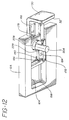
- Figs. 12-15B show the pole clamp 30 and the mechanism for moving the pole clamp between a storage position where it is substantially flush with pump housing 12, as shown in Fig. 14B, and a deployed position as shown in Fig. 14A.
- the pole clamp is operated by turning knob 28 shown in Figs. 1 and 2.
- the pole clamp 30 has a generally L-shaped construction, the longer section thereof being slidably mounted within a recess 164 within base 12A.
- a generally rectangular opening 166 extends through the longer section of pole clamp 30.
- a rectangular protrusion 168 extends within opening 166 at a corner thereof.
- a wall 170 having a surface 172 including ratchet teeth extends from a surface of pole clamp 30 towards the drive mechanism compartment cover 12D.
- Wall 170 adjoins the lower edge of the pole clamp 30 and extends below a recessed area 174 therein.
- the clamping surface 32 of pole clamp 30 facing the drive mechanism compartment cover 12D includes centrally located recessed area 174 which is bounded by a peripheral wall 176. Opening 166 extends through recessed area 174 while toothed wall 170 extends from peripheral wall 176.
- a carriage 178 is slidably positioned within recessed area 174. Carriage 178 includes an oval opening 180 which is aligned with a portion of opening 166 extending through pole clamp 30.
- An arcuate recess 182 is formed within carriage 178 near the inner end thereof.
- An integral peg 184 extends from carriage, and is located adjacent to the arcuate recess.
- a pawl 186 is pivotably mounted to peg 184.
- Pawl 186 includes a set of ratchet teeth 188 which are engageable with toothed surface 172 of wall 170 extending from pole clamp 30.
- a peg 190 extends from pawl 186 and into arcuate recess 182.
- a spring 192 positioned within arcuate recess 182 engages peg 190, thereby urging pawl 186 towards engagement with toothed surface 172 of wall 170.
- Clamp 30 is thereby releasably locked to carriage 178.
- the side of pole clamp 30 opposite to wall 170 includes an elongate slot 194 extending along an edge thereof.
- a peg 196 extends from the inner end of slot 194.
- a slot 198 is provided within base 12A which at least partially overlaps slot 194 in pole clamp 30.
- a peg 200 extends from one end of slot 198.
- An extension spring 202 is secured to pegs 196, 200 and resiliently urges pole clamp 30 towards the open position shown in Fig. 14A.
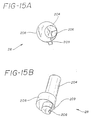
- knob 28 for controlling the pole clamp 30 is shown without the cap portion thereof.
- Knob 28 includes a cylindrical shaft 204 having a notch 206 defined in the lower end thereof. The shaft is secured to an eccentric cam 208. The axis of eccentric cam 208 is offset from that of shaft 204 by about an eighth of an inch. Shaft 204 is rotatably fixed to housing 12.
- Eccentric cam 208 is positioned within oval opening 180 of carriage 178 while the notched end portion extends within elongate opening 166 within pole clamp 30. The purpose of oval opening 180 is simply to provide clearance for eccentric cam 208. Lateral movement of carriage 178 is restricted by the degree to which eccentric cam 208 is offset from the axis of shaft 204.
- a peg 209 extends radially from eccentric cam 208.
- pump 10 is placed in adjoining relation to an I.V. pole 210 (shown cut in two for clarity) or the like in the manner shown in Fig. 14A.
- Pole clamp 30 is manually pushed inwardly until the I.V. pole abuts against both the shorter section of pole clamp 30 and recessed side 212 of the pump.
- the teeth on upper surface 172 of wall 170 are oriented such that they slide along pawl 186 as pole clamp 30 is moved with respect to carriage 178.
- the engagement of pawl 186 and surface 172 prevents pole clamp 30 from moving open again under the force of spring 202.
- Knob 28 is then turned about ninety degrees, causing eccentric cam 208 to move carriage 178 and pole clamp 30 by an additional fraction of an inch (i.e.
- Pole clamp 30 is constructed such that knob 28 cannot be turned until pole clamp 30 is pushed in towards the I.V. pole from its fully extended position. As shown in Fig. 14A, the protrusion 168 is positioned within notch 206 when pole clamp 30 is fully extended. Knob 28 can only be turned when protrusion 168 is moved out of the notch.
- the pump may be removed from the I.V. pole by turning knob 28 in the opposite direction from that used to tighten the clamp.
- the initial rotation of knob 28 causes pole clamp 30 to move outwardly a fraction of an inch due to the movement of eccentric cam 208.
- Further rotation causes peg 209 extending from eccentric cam 208 to engage pawl 186 and rotate it about peg 184 extending from carriage 178.
- the teeth of pawl 186 are thereby disengaged from those of upper surface 172.
- spring 202 causes pole clamp 30 to move to the fully extended position where the pump can easily be removed from the pole.
Claims (10)
- Pompe d'injection (10) destinée à pomper un fluide d'une seringue par poussée du piston de la seringue, la pompe comprenant :un dispositif de serrage (128) destiné à supporter la seringue,un dispositif poussoir (22) de seringue destiné à pousser le piston de la seringue,un dispositif (23) d'entraînement du dispositif poussoir (22) de seringue,un dispositif de coopération (44, 46) destiné à mettre en coopération le dispositif d'entraînement (23) et à le mettre hors du fonctionnement, etun dispositif de commande (26) destiné à commander le dispositif de coopération (44, 46), le dispositif de commande comprenant un dispositif destiné à mettre sélectivement le dispositif d'entraînement (23) en fonctionnement et hors de fonctionnement, caractérisé en ce qu'il comporte un dispositif (130, 132, 134, 136) de blocage et de déblocage du dispositif de serrage (128), et en ce que le dispositif de commande est sous forme d'un seul dispositif de commande (26) qui provoque le blocage et le déblocage sélectif du dispositif de serrage (128) par le dispositif de blocage (130, 132, 134, 136) et provoque la mise sélective en coopération du dispositif d'entraînement (23) et sa mise hors de fonctionnement de manière pratiquement simultanée par le dispositif de coopération (44, 46).
- Pompe d'injection selon la revendication 1, dans laquelle le dispositif de commande (26) comporte un dispositif de manoeuvre (68) destiné à provoquer la mise du dispositif de coopération (44, 46) en coopération avec le dispositif d'entraînement (23) uniquement lorsque le dispositif de serrage (128) est bloqué.
- Pompe d'injection selon la revendication 1, dans laquelle le dispositif de commande (26) comprend un dispositif de manoeuvre (68) destiné à bloquer et débloquer sélectivement le dispositif de serrage (128) lorsque le dispositif d'entraînement (23) reste hors de fonctionnement.
- Pompe d'injection selon la revendication 1, dans laquelle le dispositif de commande (26) comporte un dispositif de manoeuvre (214) destiné à commander le dispositif d'entraînement (23) afin que le dispositif poussoir (22) pousse le piston de la seringue.
- Pompe d'injection selon la revendication 1, dans laquelle le dispositif de blocage (130, 132, 134, 136) comporte un organe d'encliquetage (130, 138) qui peut coopérer avec le dispositif de serrage (128, 140).
- Pompe d'injection selon la revendication 1, dans laquelle le dispositif de commande (26) comporte un dispositif de manoeuvre (68) destiné à provoquer la mise du dispositif de coopération (44, 46) en coopération avec le dispositif d'entraînement (23) de manière automatique lorsque le dispositif de blocage (130, 132, 134, 136) bloque le dispositif de serrage (128), et à provoquer le déblocage du dispositif de serrage (128) de manière automatique par le dispositif de blocage (130, 132, 134, 136) lorsque le dispositif de coopération (44, 46) provoque la mise hors de fonctionnement du dispositif de serrage (128).
- Pompe d'injection selon la revendication 1, dans laquelle le dispositif de commande (26) comporte un premier arbre (68) destiné à supporter une came (145) qui peut être commandée par le dispositif de commande (26) et à provoquer le blocage et le déblocage sélectif du dispositif de serrage (128, 140) par le dispositif de blocage (130, 132, 134, 136), et une seconde surface de came (66) destinée à provoquer la mise sélective en fonctionnement et hors de fonctionnement du dispositif d'entraînement (23) par le dispositif de coopération (44, 46).
- Pompe d'injection selon la revendication 7, dans laquelle la première surface de came (145) et la seconde surface de came (66) sont orientées de manière que la seconde surface de came (66) provoque la mise en fonctionnement du dispositif d'entraînement (23) par le dispositif de coopération (44, 46) uniquement lorsque le dispositif de serrage (128) est bloqué.
- Pompe d'injection selon la revendication 7, dans laquelle la première surface de came (145) et la seconde surface de came (66) sont orientées de manière que la première surface de came (145) puisse provoquer le blocage et le déblocage du dispositif de serrage (128) par le dispositif de blocage (130, 132, 134, 136) lorsque le dispositif d'entraînement (23) est hors de fonctionnement.
- Pompe d'injection selon la revendication 7, dans laquelle la première surface de came (145) et la seconde surface de came (66) sont orientées de manière que la seconde surface de came (66) provoque la mise en coopération automatique du dispositif d'entraînement (23) par le dispositif de coopération (44, 46) lorsque la première surface de came (145) provoque le blocage du dispositif de serrage (128) par le dispositif de blocage (130, 132, 134, 136), et la première surface de came (145) provoque le déblocage automatique du dispositif de serrage (128) par le dispositif de blocage (130, 132, 134, 136) lorsque la seconde surface de came (66) provoque la mise hors de fonctionnement du dispositif d'entraînement (23) par le dispositif de coopération (44, 46).
Applications Claiming Priority (2)
| Application Number | Priority Date | Filing Date | Title |
|---|---|---|---|
| US875895 | 1992-04-29 | ||
| US07/875,895 US5261884A (en) | 1992-04-29 | 1992-04-29 | Syringe pump control system |
Publications (2)
| Publication Number | Publication Date |
|---|---|
| EP0567962A1 EP0567962A1 (fr) | 1993-11-03 |
| EP0567962B1 true EP0567962B1 (fr) | 1996-10-30 |
Family
ID=25366562
Family Applications (1)
| Application Number | Title | Priority Date | Filing Date |
|---|---|---|---|
| EP93106716A Expired - Lifetime EP0567962B1 (fr) | 1992-04-29 | 1993-04-26 | Système de contrÔle pour pompe seringue |
Country Status (5)
| Country | Link |
|---|---|
| US (1) | US5261884A (fr) |
| EP (1) | EP0567962B1 (fr) |
| JP (1) | JPH0749054B2 (fr) |
| CA (1) | CA2094764C (fr) |
| DE (2) | DE69305680T2 (fr) |
Cited By (5)
| Publication number | Priority date | Publication date | Assignee | Title |
|---|---|---|---|---|
| US8105269B2 (en) | 2008-10-24 | 2012-01-31 | Baxter International Inc. | In situ tubing measurements for infusion pumps |
| US8137083B2 (en) | 2009-03-11 | 2012-03-20 | Baxter International Inc. | Infusion pump actuators, system and method for controlling medical fluid flowrate |
| US8382447B2 (en) | 2009-12-31 | 2013-02-26 | Baxter International, Inc. | Shuttle pump with controlled geometry |
| US8567235B2 (en) | 2010-06-29 | 2013-10-29 | Baxter International Inc. | Tube measurement technique using linear actuator and pressure sensor |
| US8696632B2 (en) | 2002-06-14 | 2014-04-15 | Baxter International Inc. | Infusion pump with battery operation capability |
Families Citing this family (69)
| Publication number | Priority date | Publication date | Assignee | Title |
|---|---|---|---|---|
| US5335658A (en) * | 1992-06-29 | 1994-08-09 | Minnesota Mining And Manufacturing Company | Intravascular blood parameter sensing system |
| DE19519278A1 (de) * | 1994-12-07 | 1997-06-12 | Wolfgang Dr Med Wagner | Druckstrahlinjektor |
| US5868710A (en) * | 1996-11-22 | 1999-02-09 | Liebel Flarsheim Company | Medical fluid injector |
| AU6179001A (en) * | 2000-05-18 | 2001-11-26 | Dentsply Int Inc | Fluid material dispensing syringe |
| US8775196B2 (en) | 2002-01-29 | 2014-07-08 | Baxter International Inc. | System and method for notification and escalation of medical data |
| US10173008B2 (en) | 2002-01-29 | 2019-01-08 | Baxter International Inc. | System and method for communicating with a dialysis machine through a network |
| US8234128B2 (en) | 2002-04-30 | 2012-07-31 | Baxter International, Inc. | System and method for verifying medical device operational parameters |
| US7150724B2 (en) | 2002-06-05 | 2006-12-19 | Cardinal Health 303, Inc. | Syringe plunger driver system |
| US6997905B2 (en) | 2002-06-14 | 2006-02-14 | Baxter International Inc. | Dual orientation display for a medical device |
| US6929619B2 (en) * | 2002-08-02 | 2005-08-16 | Liebel-Flarshiem Company | Injector |
| CA2820537C (fr) | 2003-04-23 | 2015-10-20 | Valeritas, Inc. | Pompe activee hydrauliquement pour l'administration de fluide |
| US7178978B2 (en) * | 2003-09-08 | 2007-02-20 | Boston Scientific Santa Rosa Corp., | Fluid mixing apparatus and method |
| US9089636B2 (en) | 2004-07-02 | 2015-07-28 | Valeritas, Inc. | Methods and devices for delivering GLP-1 and uses thereof |
| US8512288B2 (en) | 2006-08-23 | 2013-08-20 | Medtronic Minimed, Inc. | Infusion medium delivery device and method with drive device for driving plunger in reservoir |
| US8840586B2 (en) | 2006-08-23 | 2014-09-23 | Medtronic Minimed, Inc. | Systems and methods allowing for reservoir filling and infusion medium delivery |
| US7641649B2 (en) | 2005-05-06 | 2010-01-05 | Medtronic Minimed, Inc. | Reservoir support and method for infusion device |
| US8137314B2 (en) | 2006-08-23 | 2012-03-20 | Medtronic Minimed, Inc. | Infusion medium delivery device and method with compressible or curved reservoir or conduit |
| US7905868B2 (en) | 2006-08-23 | 2011-03-15 | Medtronic Minimed, Inc. | Infusion medium delivery device and method with drive device for driving plunger in reservoir |
| US20080097291A1 (en) | 2006-08-23 | 2008-04-24 | Hanson Ian B | Infusion pumps and methods and delivery devices and methods with same |
| US8277415B2 (en) | 2006-08-23 | 2012-10-02 | Medtronic Minimed, Inc. | Infusion medium delivery device and method with drive device for driving plunger in reservoir |
| CN100371035C (zh) * | 2005-09-30 | 2008-02-27 | 深圳市深科医疗器械技术开发有限公司 | 一种无泵门结构的输液泵 |
| CA2641569C (fr) | 2006-02-09 | 2015-10-06 | Deka Products Limited Partnership | Systemes et procedes d'apport de fluide |
| ES2566058T3 (es) | 2006-03-30 | 2016-04-08 | Valeritas, Inc. | Dispositivo de suministro de fluidos de múltiples cartuchos |
| US7455663B2 (en) | 2006-08-23 | 2008-11-25 | Medtronic Minimed, Inc. | Infusion medium delivery system, device and method with needle inserter and needle inserter device and method |
| US7811262B2 (en) | 2006-08-23 | 2010-10-12 | Medtronic Minimed, Inc. | Systems and methods allowing for reservoir filling and infusion medium delivery |
| US7828764B2 (en) | 2006-08-23 | 2010-11-09 | Medtronic Minimed, Inc. | Systems and methods allowing for reservoir filling and infusion medium delivery |
| US7794434B2 (en) | 2006-08-23 | 2010-09-14 | Medtronic Minimed, Inc. | Systems and methods allowing for reservoir filling and infusion medium delivery |
| US8454560B2 (en) * | 2006-12-05 | 2013-06-04 | Mallinckrodt Llc | Syringe mount for a medical fluid injector |
| US7959715B2 (en) | 2007-04-30 | 2011-06-14 | Medtronic Minimed, Inc. | Systems and methods allowing for reservoir air bubble management |
| US8434528B2 (en) | 2007-04-30 | 2013-05-07 | Medtronic Minimed, Inc. | Systems and methods for reservoir filling |
| US7963954B2 (en) | 2007-04-30 | 2011-06-21 | Medtronic Minimed, Inc. | Automated filling systems and methods |
| US8613725B2 (en) | 2007-04-30 | 2013-12-24 | Medtronic Minimed, Inc. | Reservoir systems and methods |
| DK2146760T3 (en) | 2007-04-30 | 2019-01-28 | Medtronic Minimed Inc | FILLING OF RESERVOIR, BUBBLE MANAGEMENT AND DELIVERY SYSTEMS FOR INFUSION MEDIA AND PROCEDURES |
| US8323250B2 (en) | 2007-04-30 | 2012-12-04 | Medtronic Minimed, Inc. | Adhesive patch systems and methods |
| US8597243B2 (en) | 2007-04-30 | 2013-12-03 | Medtronic Minimed, Inc. | Systems and methods allowing for reservoir air bubble management |
| US8986253B2 (en) | 2008-01-25 | 2015-03-24 | Tandem Diabetes Care, Inc. | Two chamber pumps and related methods |
| US10089443B2 (en) | 2012-05-15 | 2018-10-02 | Baxter International Inc. | Home medical device systems and methods for therapy prescription and tracking, servicing and inventory |
| US8408421B2 (en) | 2008-09-16 | 2013-04-02 | Tandem Diabetes Care, Inc. | Flow regulating stopcocks and related methods |
| CA2737461A1 (fr) | 2008-09-19 | 2010-03-25 | Tandem Diabetes Care, Inc. | Dispositif de mesure de la concentration d'un solute et procedes associes |
| US7748520B1 (en) * | 2008-09-23 | 2010-07-06 | Activar Technical Products Group, Inc. | Slip roller conveyor |
| US8554579B2 (en) | 2008-10-13 | 2013-10-08 | Fht, Inc. | Management, reporting and benchmarking of medication preparation |
| EP2459251B1 (fr) | 2009-07-30 | 2014-03-12 | Tandem Diabetes Care, Inc. | Système de pompe de perfusion à cartouche jetable comprenant une décharge de pression et une rétroaction de pression |
| CA2736841C (fr) | 2010-04-15 | 2014-02-18 | Teneo Innovations Inc. | Dispositif et dispositif de commande electronique pour la commande d'un piston de seringue |
| EP2830499B8 (fr) | 2012-03-30 | 2019-04-03 | Insulet Corporation | Dispositif d'administration de fluide avec outil d'accès transcutané, mécanisme d'insertion et contrôle de glycémie destine à être utilisé avec le dispositif |
| US9180242B2 (en) | 2012-05-17 | 2015-11-10 | Tandem Diabetes Care, Inc. | Methods and devices for multiple fluid transfer |
| KR101266756B1 (ko) * | 2012-06-20 | 2013-05-28 | 김동식 | 플러싱 기능을 가진 수액조절기 |
| WO2014065871A2 (fr) | 2012-10-26 | 2014-05-01 | Baxter Corporation Englewood | Acquisition d'images améliorée pour système de préparation de dose médicale |
| EP3453377A1 (fr) | 2012-10-26 | 2019-03-13 | Baxter Corporation Englewood | Station de travail améliorée pour système de préparation de doses médicales |
| US9173998B2 (en) | 2013-03-14 | 2015-11-03 | Tandem Diabetes Care, Inc. | System and method for detecting occlusions in an infusion pump |
| EP2910264B1 (fr) * | 2014-02-20 | 2018-05-30 | Fresenius Vial SAS | Dispositif de maintien pour une pompe à seringue |
| US11107574B2 (en) | 2014-09-30 | 2021-08-31 | Baxter Corporation Englewood | Management of medication preparation with formulary management |
| AU2015358483A1 (en) | 2014-12-05 | 2017-06-15 | Baxter Corporation Englewood | Dose preparation data analytics |
| SG10202107686XA (en) | 2015-03-03 | 2021-08-30 | Baxter Corp Englewood | Pharmacy workflow management with integrated alerts |
| US10413665B2 (en) | 2015-11-25 | 2019-09-17 | Insulet Corporation | Wearable medication delivery device |
| WO2018035032A1 (fr) | 2016-08-14 | 2018-02-22 | Insulet Corporation | Dispositif automatique d'administration de médicament avec mécanisme de déclenchement |
| US10751478B2 (en) | 2016-10-07 | 2020-08-25 | Insulet Corporation | Multi-stage delivery system |
| US10780217B2 (en) | 2016-11-10 | 2020-09-22 | Insulet Corporation | Ratchet drive for on body delivery system |
| WO2018136699A1 (fr) | 2017-01-19 | 2018-07-26 | Insulet Corporation | Réduction du volume de rétention de cartouche |
| WO2018156548A1 (fr) | 2017-02-22 | 2018-08-30 | Insulet Corporation | Mécanismes d'introduction d'aiguille pour récipients de médicament |
| US10695485B2 (en) | 2017-03-07 | 2020-06-30 | Insulet Corporation | Very high volume user filled drug delivery device |
| US10973978B2 (en) | 2017-08-03 | 2021-04-13 | Insulet Corporation | Fluid flow regulation arrangements for drug delivery devices |
| US11280327B2 (en) | 2017-08-03 | 2022-03-22 | Insulet Corporation | Micro piston pump |
| US11786668B2 (en) | 2017-09-25 | 2023-10-17 | Insulet Corporation | Drug delivery devices, systems, and methods with force transfer elements |
| WO2019067367A1 (fr) | 2017-09-26 | 2019-04-04 | Insulet Corporation | Module de mécanisme d'aiguille pour dispositif d'administration de médicament |
| US11147931B2 (en) | 2017-11-17 | 2021-10-19 | Insulet Corporation | Drug delivery device with air and backflow elimination |
| US10874803B2 (en) | 2018-05-31 | 2020-12-29 | Insulet Corporation | Drug cartridge with drive system |
| US11229736B2 (en) | 2018-06-06 | 2022-01-25 | Insulet Corporation | Linear shuttle pump for drug delivery |
| US11446435B2 (en) | 2018-11-28 | 2022-09-20 | Insulet Corporation | Drug delivery shuttle pump system and valve assembly |
| US11369735B2 (en) | 2019-11-05 | 2022-06-28 | Insulet Corporation | Component positioning of a linear shuttle pump |
Family Cites Families (15)
| Publication number | Priority date | Publication date | Assignee | Title |
|---|---|---|---|---|
| US3858581A (en) * | 1973-07-02 | 1975-01-07 | Dean Kamen | Medication injection device |
| GB1595972A (en) * | 1977-03-09 | 1981-08-19 | Nat Res Dev | Syringe driving apparatus |
| US4424720A (en) * | 1980-12-15 | 1984-01-10 | Ivac Corporation | Mechanism for screw drive and syringe plunger engagement/disengagement |
| GB2152770B (en) * | 1983-11-15 | 1987-04-29 | Yokogawa Hokushin Electric | Dc/dc converter |
| US4846797A (en) * | 1985-05-14 | 1989-07-11 | Intelligent Medicine, Inc. | Syringe positioning device for enhancing fluid flow control |
| US4695271A (en) * | 1986-02-03 | 1987-09-22 | Liebel-Flarsheim Company | Angiographic injector |
| BE904426A (fr) * | 1986-03-14 | 1986-06-30 | Maraite Jean | Perfectionnements aux pousse-seringue. |
| US4804368A (en) * | 1986-12-05 | 1989-02-14 | C. R. Bard, Inc. | Battery operated miniature syringe infusion pump and improved halfnut therefor |
| US5034004A (en) * | 1987-06-19 | 1991-07-23 | The University Of Melbourne | Infusion pump and drive systems therefor |
| JPH01139074A (ja) * | 1987-11-27 | 1989-05-31 | Terumo Corp | シリンジ付勢装置 |
| JPH01284266A (ja) * | 1988-05-09 | 1989-11-15 | Terumo Corp | シリンジ取外し装置付シリンジポンプ |
| JP2717808B2 (ja) * | 1988-08-10 | 1998-02-25 | テルモ株式会社 | シリンジポンプ |
| US5101679A (en) * | 1990-01-08 | 1992-04-07 | Ivac Corporation | Screw drive engagement/disengagement and decoupling mechanism |
| US5176646A (en) * | 1991-02-19 | 1993-01-05 | Takayuki Kuroda | Motorized syringe pump |
| US5106375A (en) * | 1991-05-23 | 1992-04-21 | Ivac Corporation | Dynamic lead screw engagement and indicator |
-
1992
- 1992-04-29 US US07/875,895 patent/US5261884A/en not_active Expired - Fee Related
-
1993
- 1993-04-23 CA CA002094764A patent/CA2094764C/fr not_active Expired - Fee Related
- 1993-04-26 DE DE69305680T patent/DE69305680T2/de not_active Expired - Fee Related
- 1993-04-26 DE DE93106716T patent/DE567962T1/de active Pending
- 1993-04-26 EP EP93106716A patent/EP0567962B1/fr not_active Expired - Lifetime
- 1993-04-28 JP JP5103076A patent/JPH0749054B2/ja not_active Expired - Lifetime
Cited By (8)
| Publication number | Priority date | Publication date | Assignee | Title |
|---|---|---|---|---|
| US8696632B2 (en) | 2002-06-14 | 2014-04-15 | Baxter International Inc. | Infusion pump with battery operation capability |
| US8888738B2 (en) | 2002-06-14 | 2014-11-18 | Baxter International Inc. | Infusion pump with multiple orientation display |
| US9514518B2 (en) | 2002-06-14 | 2016-12-06 | Baxter International Inc. | Infusion pump including syringe plunger position sensor |
| US8105269B2 (en) | 2008-10-24 | 2012-01-31 | Baxter International Inc. | In situ tubing measurements for infusion pumps |
| US8496613B2 (en) | 2008-10-24 | 2013-07-30 | Baxter International Inc. | In situ tubing measurements for infusion pumps |
| US8137083B2 (en) | 2009-03-11 | 2012-03-20 | Baxter International Inc. | Infusion pump actuators, system and method for controlling medical fluid flowrate |
| US8382447B2 (en) | 2009-12-31 | 2013-02-26 | Baxter International, Inc. | Shuttle pump with controlled geometry |
| US8567235B2 (en) | 2010-06-29 | 2013-10-29 | Baxter International Inc. | Tube measurement technique using linear actuator and pressure sensor |
Also Published As
| Publication number | Publication date |
|---|---|
| EP0567962A1 (fr) | 1993-11-03 |
| DE567962T1 (de) | 1994-03-17 |
| US5261884A (en) | 1993-11-16 |
| JPH067438A (ja) | 1994-01-18 |
| CA2094764C (fr) | 1999-03-16 |
| DE69305680D1 (de) | 1996-12-05 |
| JPH0749054B2 (ja) | 1995-05-31 |
| CA2094764A1 (fr) | 1993-10-30 |
| DE69305680T2 (de) | 1997-05-07 |
Similar Documents
| Publication | Publication Date | Title |
|---|---|---|
| EP0567962B1 (fr) | Système de contrÔle pour pompe seringue | |
| EP0567945B1 (fr) | Pompe seringue avec fixation verrouillable préarmée de seringue | |
| EP0567944B1 (fr) | Pompe seringue avec détection de la position du corps de la seringue | |
| EP0567923B1 (fr) | Dispositif de poussage pour pousse-seringue | |
| EP0567946B1 (fr) | Pince et pompe d'infusion avec pince | |
| JP3508024B2 (ja) | 静脈内チューブ安全装置 | |
| EP0737079B1 (fr) | Pompe medicale a perfusion | |
| US9022983B2 (en) | Infusion pump | |
| US6117115A (en) | Medical tubing slide clamp device for determining proper tubing size and functional characteristics | |
| US20170258985A1 (en) | Syringe infusion pump security | |
| JP2007222485A (ja) | 輸液安全装置とこれを用いた輸液ポンプ | |
| EP2655885B1 (fr) | Système d'identification et de chargement de dispositif de distribution de fluide | |
| WO2011121923A1 (fr) | Pompe à perfusion | |
| CA2871021A1 (fr) | Distributeurs de medicaments | |
| JPS59141955A (ja) | 液体流量制御装置 | |
| JP2001218841A (ja) | 輸液ポンプ用カセットおよびそれを用いた輸液ポンプ | |
| JPH09262291A (ja) | クランプおよびチューブ閉塞方法 |
Legal Events
| Date | Code | Title | Description |
|---|---|---|---|
| PUAI | Public reference made under article 153(3) epc to a published international application that has entered the european phase |
Free format text: ORIGINAL CODE: 0009012 |
|
| AK | Designated contracting states |
Kind code of ref document: A1 Designated state(s): DE FR GB IT |
|
| ITCL | It: translation for ep claims filed |
Representative=s name: JACOBACCI CASETTA & PERANI S.P.A. |
|
| EL | Fr: translation of claims filed | ||
| DET | De: translation of patent claims | ||
| 17P | Request for examination filed |
Effective date: 19940219 |
|
| 17Q | First examination report despatched |
Effective date: 19941209 |
|
| GRAG | Despatch of communication of intention to grant |
Free format text: ORIGINAL CODE: EPIDOS AGRA |
|
| GRAH | Despatch of communication of intention to grant a patent |
Free format text: ORIGINAL CODE: EPIDOS IGRA |
|
| GRAH | Despatch of communication of intention to grant a patent |
Free format text: ORIGINAL CODE: EPIDOS IGRA |
|
| GRAA | (expected) grant |
Free format text: ORIGINAL CODE: 0009210 |
|
| AK | Designated contracting states |
Kind code of ref document: B1 Designated state(s): DE FR GB IT |
|
| ITF | It: translation for a ep patent filed |
Owner name: JACOBACCI & PERANI S.P.A. |
|
| REF | Corresponds to: |
Ref document number: 69305680 Country of ref document: DE Date of ref document: 19961205 |
|
| ET | Fr: translation filed | ||
| PLBE | No opposition filed within time limit |
Free format text: ORIGINAL CODE: 0009261 |
|
| STAA | Information on the status of an ep patent application or granted ep patent |
Free format text: STATUS: NO OPPOSITION FILED WITHIN TIME LIMIT |
|
| 26N | No opposition filed | ||
| PGFP | Annual fee paid to national office [announced via postgrant information from national office to epo] |
Ref country code: FR Payment date: 20010330 Year of fee payment: 9 |
|
| PGFP | Annual fee paid to national office [announced via postgrant information from national office to epo] |
Ref country code: DE Payment date: 20010402 Year of fee payment: 9 |
|
| PGFP | Annual fee paid to national office [announced via postgrant information from national office to epo] |
Ref country code: GB Payment date: 20010403 Year of fee payment: 9 |
|
| REG | Reference to a national code |
Ref country code: GB Ref legal event code: IF02 |
|
| PG25 | Lapsed in a contracting state [announced via postgrant information from national office to epo] |
Ref country code: GB Free format text: LAPSE BECAUSE OF NON-PAYMENT OF DUE FEES Effective date: 20020426 |
|
| PG25 | Lapsed in a contracting state [announced via postgrant information from national office to epo] |
Ref country code: DE Free format text: LAPSE BECAUSE OF NON-PAYMENT OF DUE FEES Effective date: 20021101 |
|
| GBPC | Gb: european patent ceased through non-payment of renewal fee |
Effective date: 20020426 |
|
| PG25 | Lapsed in a contracting state [announced via postgrant information from national office to epo] |
Ref country code: FR Free format text: LAPSE BECAUSE OF NON-PAYMENT OF DUE FEES Effective date: 20021231 |
|
| REG | Reference to a national code |
Ref country code: FR Ref legal event code: ST |
|
| PG25 | Lapsed in a contracting state [announced via postgrant information from national office to epo] |
Ref country code: IT Free format text: LAPSE BECAUSE OF NON-PAYMENT OF DUE FEES;WARNING: LAPSES OF ITALIAN PATENTS WITH EFFECTIVE DATE BEFORE 2007 MAY HAVE OCCURRED AT ANY TIME BEFORE 2007. THE CORRECT EFFECTIVE DATE MAY BE DIFFERENT FROM THE ONE RECORDED. Effective date: 20050426 |