EP0567894A1 - Device for guiding a workpiece or a tool while machining toric or spheric surfaces of ophtalmic lenses on grinding or polishing machines - Google Patents
Device for guiding a workpiece or a tool while machining toric or spheric surfaces of ophtalmic lenses on grinding or polishing machines Download PDFInfo
- Publication number
- EP0567894A1 EP0567894A1 EP93106347A EP93106347A EP0567894A1 EP 0567894 A1 EP0567894 A1 EP 0567894A1 EP 93106347 A EP93106347 A EP 93106347A EP 93106347 A EP93106347 A EP 93106347A EP 0567894 A1 EP0567894 A1 EP 0567894A1
- Authority
- EP
- European Patent Office
- Prior art keywords
- pressure medium
- lens
- sleeve
- cylinder
- chamber
- Prior art date
- Legal status (The legal status is an assumption and is not a legal conclusion. Google has not performed a legal analysis and makes no representation as to the accuracy of the status listed.)
- Granted
Links
- 238000005498 polishing Methods 0.000 title claims abstract description 19
- 238000003754 machining Methods 0.000 title claims description 11
- 238000012545 processing Methods 0.000 claims description 9
- 230000003287 optical effect Effects 0.000 claims description 3
- 238000006073 displacement reaction Methods 0.000 claims description 2
- 230000002093 peripheral effect Effects 0.000 abstract description 3
- 238000005096 rolling process Methods 0.000 description 9
- 230000008859 change Effects 0.000 description 6
- 239000003795 chemical substances by application Substances 0.000 description 3
- 230000001447 compensatory effect Effects 0.000 description 3
- 238000013461 design Methods 0.000 description 3
- 239000011521 glass Substances 0.000 description 3
- 238000004891 communication Methods 0.000 description 2
- 230000000295 complement effect Effects 0.000 description 2
- 230000008878 coupling Effects 0.000 description 2
- 238000010168 coupling process Methods 0.000 description 2
- 238000005859 coupling reaction Methods 0.000 description 2
- 238000005452 bending Methods 0.000 description 1
- 230000005540 biological transmission Effects 0.000 description 1
- 230000000903 blocking effect Effects 0.000 description 1
- 238000012937 correction Methods 0.000 description 1
- 238000011161 development Methods 0.000 description 1
- 230000018109 developmental process Effects 0.000 description 1
- 239000013536 elastomeric material Substances 0.000 description 1
- 239000007789 gas Substances 0.000 description 1
- 229910052500 inorganic mineral Inorganic materials 0.000 description 1
- 239000007788 liquid Substances 0.000 description 1
- 238000004519 manufacturing process Methods 0.000 description 1
- 239000012528 membrane Substances 0.000 description 1
- 239000011707 mineral Substances 0.000 description 1
- 238000007517 polishing process Methods 0.000 description 1
- 230000002787 reinforcement Effects 0.000 description 1
- 238000000926 separation method Methods 0.000 description 1
- 230000007704 transition Effects 0.000 description 1
- 238000009423 ventilation Methods 0.000 description 1
Images


Classifications
-
- B—PERFORMING OPERATIONS; TRANSPORTING
- B24—GRINDING; POLISHING
- B24B—MACHINES, DEVICES, OR PROCESSES FOR GRINDING OR POLISHING; DRESSING OR CONDITIONING OF ABRADING SURFACES; FEEDING OF GRINDING, POLISHING, OR LAPPING AGENTS
- B24B37/00—Lapping machines or devices; Accessories
- B24B37/27—Work carriers
- B24B37/30—Work carriers for single side lapping of plane surfaces
-
- B—PERFORMING OPERATIONS; TRANSPORTING
- B24—GRINDING; POLISHING
- B24B—MACHINES, DEVICES, OR PROCESSES FOR GRINDING OR POLISHING; DRESSING OR CONDITIONING OF ABRADING SURFACES; FEEDING OF GRINDING, POLISHING, OR LAPPING AGENTS
- B24B13/00—Machines or devices designed for grinding or polishing optical surfaces on lenses or surfaces of similar shape on other work; Accessories therefor
- B24B13/005—Blocking means, chucks or the like; Alignment devices
Definitions
- the invention relates to a device for guiding a workpiece or tool in the machining of toric or spherical surfaces of optical lenses on grinding or polishing machines, according to the preamble of patent claim 1.
- the device is preferably intended for machining toric surfaces.
- a toric surface is understood to mean a non-rotationally symmetrical aspherical surface which has two radii of different sizes in two sections perpendicular to one another, while all other sections represent curves of a higher order.
- the grinding and polishing of the blanks of toric lenses is usually carried out using tools which have a continuous or interrupted toric surface which is complementary to the lens surface. It is essential that the two arcuate profiles of the toric lens are perpendicular to each other, especially in the case of correction lenses. It is therefore essential that in the course of clear grinding and polishing, the two particular perpendicular planes of the Grinding or polishing tools that are moved past a point on the surface of the lens always remain parallel to themselves.
- devices for clear grinding and polishing have a tool which is caused to perform the most diverse possible orbital movements, but no rotary movement is provided about a vertical axis standing on the toric surface.
- the devices for the clear grinding and polishing of toric lenses have a guide device which prevents such rotary movements and a driver device which ensures a change in position of the tool with respect to the lens.
- the driver device essentially has a ball joint, in the axial direction of which the tool acts on the lens, and which deflects the various movements which cause a relative change in position between the lens and tool, a direction perpendicular to its axis, and thus a gimbal balance between Allows lens and tool.
- a number of guiding devices are known which operate on this principle.
- the known guiding devices which are used for individual machining are those in which the lens or the tool is held in place, while the other element, ie the tool or the lens, is guided by forks, drive rods and / or joints, in particular ball joints .
- the guide systems working with a fork tend to make an eccentric adjustment, which prevents the torus from being fully realized.
- the lens or tool is caused to rotate, while the other element, ie the tool or lens, is guided through a device which also has forks, drive rods and / or joints.
- the devices used for guiding are correspondingly structured.
- the lining for optical lenses known from German patent specification 22 52 503 made a significant advance in relation to the problems shown.
- the orientation of the torus axes is not achieved via forks and the two otherwise usual ball pins, but rather a form-fitting lens carrier is used, which is guided by a rolling bellows in the circumferential direction and which holds the intermediate piece to be machined by means of an air cushion on the tool (or vice versa).
- the lens carrier is designed to be axially displaceable, with the radial guide using a spherical pin Tip occurs around which the lens wearer can perform an oscillating movement, which is necessary for the positive, homokinetic adjustment of the tool and lens.
- the effective contact pressure is transferred to the lens carrier via the roller bellows.
- the entire chuck thus forms a homokinetic coupling, which allows the torque-free transmission of torques between the lens holder and the tool and, at the same time, hermetically seals the ball joint against the abrasive polishing and grinding agents.
- the known chuck described above is according to the prior art (Loh Toro-X 2000, grinding and polishing machine for the recipe production of the companies Loh Optikmaschinen KG in CH-4702 Oensingen and Wilhelm Loh Wetzlar Optikmaschinen GmbH Co. KG in DE-6330 Wetzlar) used on an axially movable quill, on the inner end of which the receiving chuck is concentrically attached.
- the respective position of the quill must be readjusted each time the workpiece or tool is changed in order to ensure that the receiving chuck functions properly.
- the known device with the advantageous bellows receiving chuck must be operated by hand for the axial movements. Workpieces can also only be changed by hand.
- the invention has for its object to provide a device based on the preamble of claim 1, in which to realize an automatic workpiece and tool change, the quill is automatically added or set and is held in the working position with optimal balancing effectiveness of the feed chuck.
- the quill is moved axially by a pressure medium cylinder and piston arrangement through a pressure medium which simultaneously actuates the receiving chuck and brings it into a position which is most suitable for homokinetic compensatory movements.
- all adjustment and delivery movements can be controlled exclusively and automatically by the pressure medium. This not only saves time, it also ensures a consistently high processing quality.
- Gases and liquids can be used as pressure medium, but compressed air is preferred.
- the desired balance of forces between the forces generated by the pressure medium cylinder and piston arrangement and the forces acting in the receiving chuck is preferably achieved in accordance with claim 2.
- the measures of claim 4 ensure that not only the piston of the pressure medium cylinder and piston assembly is retracted after a working cycle, but that the intake chuck is brought into a position by the vacuum used, which favors an automatic change of the parts to be changed.
- Claim 5 contains features for a special design of the parts forming the ball joint and their attachment to the quill.
- An expedient design of the guide pin carrying the ball head of the ball joint can be seen from claim 6.
- Claims 7 and 8 characterize a stop arrangement for the guide pin with integrated valve device for blocking the pressure medium supply to the receiving chuck when the guide pin is pushed out to the maximum.
- the design of the device according to claims 9 to 11 is advantageous. This ensures that the intermediate piece holding the lens is latched and positioned on the lens holder of the receiving chuck, which facilitates the automatic loading and positioning of the parts to be changed.
- the device can also be designed according to claim 12.
- the device shown in Fig. 1 is part of a grinding or polishing machine, not shown, on which several of the devices shown (for example two) can be arranged in parallel. Such machines are used for prescription lens processing.
- a rotationally symmetrical receiving chuck 2 is attached at the lower end of a quill 1.
- the receiving chuck 2 has a bell-shaped flange 3 with a concentric hollow pin 4 and is non-rotatably and axially non-displaceably attached to the lower end of the sleeve 1 and fastened there in a suitable manner.
- the outer wall 7 of a bellows 8 is firmly and tightly clamped between a peripheral wall 5 of the flange 3 and an outer ring 6 attached to it.
- the inner wall 9 of the roller bellows 8 is fastened tightly to the cylindrical peripheral surface of a lens carrier 10.
- the bellows 8 consists of an elastomeric material with an embedded reinforcement insert, which does not hinder the bending of the bellows, but excludes its elastic expansion.
- the bellows can roll without being stretched and is rigid in the circumferential direction. Rotations of the lens carrier 10 with respect to the flange 3 can therefore not occur in the machining operation.
- the rolling bellows 8 seals an articulated chamber 12 essentially delimited by the flange 3 and the lens carrier 10.
- a ball joint consisting of a ball head 13 which engages in a ball socket 14 located in the lens carrier 10.
- the ball head 13 is located at the free end of a guide pin 15 which is guided axially displaceably in a piston-like manner within an axial bore 11 which is continuous over the length of the sleeve 1 and within a guide bush 16 inserted therein.
- the guide pin 15 has a longitudinal bore 17 closed at both ends, which is connected by an upper transverse bore 18 to the axial bore 11 and by a lower transverse bore 19 to the joint chamber 12 forming a pressure medium space.
- the receiving chuck 2 with its ball joint 13, 14 and the rolling bellows 8 forms an exactly backlash-free, homokinetic coupling between the lens carrier 10 and the flange 3 in the circumferential direction because of the rigidity of the rolling bellows Rigid bellows 8 does not hinder the tiltability of the lens carrier 10 about the ball joint 13, 14 relative to the flange 3, so that tilting compensatory movements of the lens carrier 10 are possible without restriction.
- the bellows 8 hermetically seals the ball joint 13, 14 against the abrasive polishing and grinding agents.
- the lens carrier 10 is detachably latched with an intermediate piece 21, which is concentrically attached thereto and holds the lens 20.
- an intermediate piece 21 is provided on a lower cylindrical wall of the lens carrier 10 and a circumferential outer groove 23 on a complementary cylindrical wall of the intermediate piece 21.
- An O-ring 24 is inserted into the circumferential inner groove 22, which is the locking element effective between the two grooves 22, 23.
- the intermediate piece 21 engages in a form-fitting and positioning manner in the lens carrier 10.
- the intermediate piece 21 sits on the grinding or polishing tool 25 with the interposition of the lens 20 fastened to it for processing.
- the sleeve 1 can be moved axially in the manner described below by a pressure medium cylinder and piston arrangement arranged coaxially thereto.
- the piston 26 is designed as an annular piston attached to the quill 1, which is displaceable within the cylinder 27 with the quill 1 acting as a piston rod.
- the cylinder 27 is closed at one end by an upper cylinder cover 29 provided with a pressure medium chamber 28.
- the pressure medium chamber 28 is located within a cup-shaped extension 30 of the cylinder cover 29.
- the sleeve 1, which dips into the pressure medium chamber 28 with its upper end, is guided axially displaceably but non-rotatably in the upper cylinder cover 29.
- a guide ring is fastened axially immovably and non-rotatably within the upper cylinder cover 29.
- the Quill 1 passes through the guide ring 31 and is non-rotatable with respect to it by multi-spline toothing elements or the like, which are partly attached to the quill 1 above the piston 26 and partly in the corresponding through bore of the guide ring 31.
- connection bore 32 for the optional supply of the pressure medium or the application of a negative pressure.
- the connection bore 32 is in constant communication with both the pressure medium chamber 28 and with a pressure medium space 33.
- the pressure medium space 33 is delimited by the cylinder 27, the upper cylinder cover 29, the outer surface of the sleeve 1 and the piston 26. Since there is no pressure difference between the pressure medium chamber 28 and the pressure medium space 33 due to the arrangement described, a seal between the sleeve 1 and the upper cylinder cover 29 or the guide ring 31 is omitted, as a result of which the sleeve 1 passes through the guide ring 31 with low friction.
- the sleeve 1 With its end carrying the receiving chuck 2, the sleeve 1 is axially displaceably guided through a lower cylinder cover 34 which closes the lower end of the cylinder 27.
- a seal between the lower cylinder cover 34 and the sleeve 1 passed through it is not necessary to reduce friction because no pressure medium is supplied to the cylinder space between the piston 26 and the lower cylinder cover 34.
- This space is in permanent communication with the outside atmosphere via a ventilation opening 35 through the lower cylinder cover 34.
- the two cylinder covers 29 and 34 and the cylinder 27 are held together by suitable means.
- the entire device can, for example, by means of the lower cylinder cover 34 on a crosshead or the like. be attached to the grinding and polishing machine, which is movably driven (not shown) in accordance with the kinematic requirements for machining toric surfaces.
- the pressure medium space of the joint chamber 12 and the pressure medium space 33 of the pressure medium cylinder and piston arrangement 26, 27 communicate with one another, i.e. are directly connected to the connection bore 32 in the case of the pressure medium chamber 33 and indirectly in the case of the pressure medium chamber of the joint chamber 12.
- the pressure medium supplied via the connection bore 32 passes through a feed bore 36 in the upper cylinder cover 29 or in the guide ring 31 into the pressure medium chamber 33.
- pressure medium of the same pressure passes from the connection bore 32 into the pressure medium chamber 28 and from there via the axial bore 11 in the sleeve 1 and via the bores 18, 17 and 19 in the guide pin 15 into the pressure medium chamber of the joint chamber 12.
- the pressure medium chamber of the joint chamber 12 and the pressure medium chamber 33 located above the piston 26 are therefore acted upon simultaneously by the pressure medium.
- the dimensions of the pressure medium effective surfaces on the piston 26, including the end ring surface of the sleeve 1 located in the pressure medium chamber 28, on the one hand, and the pressure medium active surfaces in the receiving chuck 2, on the other hand, are designed for a balance between the axially effective forces directed in the opposite working position.
- the bellows 8 should have the cross-sectional configuration shown in FIGS.
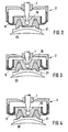
- Tilting movements ie compensating movements of the lens carrier 10, on the other hand, are more difficult or at least restricted if the rolling bellows 8 have the configuration shown in FIGS. 2 and 3 shows.
- the pressure medium applied to the receiving chuck 2 is too high, while in FIG. 3 it is too low.
- there is a tightening of the bellows which impairs the tilting movement of the rolling bellows 8.
- the quill 1 and the receiving chuck 2 assume approximately the position shown in FIG. 1, in which the aforementioned balance of forces is present and a sufficient contact pressure is applied between the workpiece and the tool for the intended machining process.
- the guide pin 15 also has a special feature illustrated by FIG. 5. When it is acted upon by the pressure medium on its end face, its outward displacement path is limited by a stop. For this purpose, an O-ring 37 inserted into a circumferential groove of the same is provided at the upper end of the guide pin 15 and, when the guide pin is pushed out to the maximum, strikes the end face 38 of the guide bush 16 inserted into the axial bore 11 of the sleeve 1. This arrangement also acts as a valve device.
- the device is moved into the working position by supplying the pressure medium to the connection bore 32.
- the pressure medium flows through the connection bore 32 into the pressure medium space 33, the pressure medium chamber 28 and via the bores described in the pressure medium space of the joint chamber 12.
- the rolling bellows 8 with the lens carrier 10 and the intermediate piece 21 holding the lens 20 is extended downward in the receiving chuck 2, the stop arrangement described with valve device at the upper end the guide pin 15 prevents an ancestor from being too wide.
- the piston 26 extends with the sleeve 1 until the workpiece, ie the lens 20, is pressed against the tool to the extent necessary for the machining.
- the device is returned to its starting position, the sleeve 1 being returned to its loading and starting position by applying a negative pressure via the connection bore 32 to the pressure medium chamber 33.
- the lens carrier 10 with the intermediate piece 21 and the processed lens 20 located thereon is lifted off the tool 25. Since the negative pressure applied also acts on the pressure medium chamber of the joint chamber 12 via the bores and spaces described, the membrane formed by the bellows 8 and the lens carrier 10 is pulled against the intermediate piece 21 and the lens 20 against the stop in the bell-shaped flange 3 .
- the precise positioning of the workpiece or of the parts carrying the workpiece required for automatic loading is achieved.
Landscapes
- Engineering & Computer Science (AREA)
- Mechanical Engineering (AREA)
- Grinding And Polishing Of Tertiary Curved Surfaces And Surfaces With Complex Shapes (AREA)
Abstract
Description
Die Erfindung bezieht sich auf eine Vorrichtung zur Führung eines Werkstücks oder Werkzeugs bei der Bearbeitung torischer oder sphärischer Flächen optischer Linsen auf Schleif- oder Poliermaschinen, entsprechend dem Oberbegriff des Patentanspruchs 1.The invention relates to a device for guiding a workpiece or tool in the machining of toric or spherical surfaces of optical lenses on grinding or polishing machines, according to the preamble of
Die Vorrichtung ist vorzugsweise für die Bearbeitung torischer Flächen bestimmt. Unter einer torischen Fläche wird eine nichtrotationssymmetrische asphärische Fläche verstanden, die in zwei zueinander senkrecht stehenden Schnitten zwei unterschiedlich große Radien aufweist, während alle übrigen Schnitte Kurven höherer Ordnung darstellen. Das Klarschleifen und Polieren der Rohlinge torischer Linsen wird üblicherweise mittels Werkzeugen durchgeführt, die eine kontinuierliche oder unterbrochene, zur Linsenfläche komplementäre, torische Fläche aufweisen. Hierbei ist wesentlich, daß die beiden kreisbogenförmigen Profile der torischen Linse senkrecht aufeinander stehen, insbesondere im Falle von Korrektionslinsen. Es ist folglich wesentlich, daß im Zuge des Klarschleifens und des Polierens die beiden besonderen senkrecht aufeinander stehenden Ebenen des Schleif- oder Polierwerkzeuges, die an einem Punkt der Oberfläche der Linse vorbeibewegt werden, immer zu sich selbst parallel bleiben. Dies bedeutet, daß ein gegenseitiges Verdrehen der Torusachsen von Werkzeug und Linse vermieden werden muß. Dementsprechend weisen Vorrichtungen zum Klarschleifen und Polieren ein Werkzeug auf, das zur Durchführung möglichst verschiedenartiger orbitaler Bewegungen veranlaßt wird, dabei ist jedoch keine Drehbewegung um eine auf der torischen Oberfläche stehende senkrechte Achse vorgesehen.The device is preferably intended for machining toric surfaces. A toric surface is understood to mean a non-rotationally symmetrical aspherical surface which has two radii of different sizes in two sections perpendicular to one another, while all other sections represent curves of a higher order. The grinding and polishing of the blanks of toric lenses is usually carried out using tools which have a continuous or interrupted toric surface which is complementary to the lens surface. It is essential that the two arcuate profiles of the toric lens are perpendicular to each other, especially in the case of correction lenses. It is therefore essential that in the course of clear grinding and polishing, the two particular perpendicular planes of the Grinding or polishing tools that are moved past a point on the surface of the lens always remain parallel to themselves. This means that mutual twisting of the torus axes of the tool and lens must be avoided. Correspondingly, devices for clear grinding and polishing have a tool which is caused to perform the most diverse possible orbital movements, but no rotary movement is provided about a vertical axis standing on the toric surface.
Die Vorrichtungen zum Klarschleifen und Polieren von torischen Linsen weisen eine Führungsvorrichtung auf, die solche Drehbewegungen verhindern, sowie eine Mitnehmervorrichtung, die eine Lageveränderung des Werkzeugs in bezug auf die Linse sicherstellt. Die Mitnehmervorrichtung weist im wesentlichen ein Kugelgelenk auf, in dessen Achsrichtung die Angriffskraft des Werkzeugs auf die Linse wirkt, und das die verschiedenen Bewegungen, die eine relative Lageveränderung zwischen Linse und Werkzeug bewirken, eine zu seiner Achse senkrechte Richtung umlenkt und somit einen kardanischen Ausgleich zwischen Linse und Werkzeug ermöglicht. Es sind eine Reihe von Führungsvorrichtungen bekannt, die nach diesem Prinzip arbeiten.The devices for the clear grinding and polishing of toric lenses have a guide device which prevents such rotary movements and a driver device which ensures a change in position of the tool with respect to the lens. The driver device essentially has a ball joint, in the axial direction of which the tool acts on the lens, and which deflects the various movements which cause a relative change in position between the lens and tool, a direction perpendicular to its axis, and thus a gimbal balance between Allows lens and tool. A number of guiding devices are known which operate on this principle.
Unter den bekannten Führungsvorrichtungen, die einer Einzelbearbeitung dienen, sind solche, bei denen die Linse oder das Werkzeug festgehalten wird, während das jeweils andere Element, d.h. das Werkzeug oder die Linse, von Gabeln, Triebstangen und/oder Gelenken, insbesondere Kugelgelenken, geführt werden. Es ist jedoch festzustellen, daß die mit einer Gabel arbeitenden Führungssysteme zu einer exzentrischen Verstellung neigen, die einer vollkommenen Realisierung des Torus entgegensteht. Bei einer anderen Vorrichtung werden die Linse oder das Werkzeug zu einer Drehbewegung veranlaßt, während das andere Element, d.h. das Werkzeug oder die Linse, durch eine Vorrichtung geführt werden, die ebenfalls Gabeln, Triebstangen und/oder Gelenke aufweist. Bei Vorrichtungen zum Klarschleifen und Polieren im fortschreitenden Betrieb sind die zur Führung verwendeten Vorrichtungen entsprechend vielgliedrig aufgebaut.Among the known guiding devices which are used for individual machining are those in which the lens or the tool is held in place, while the other element, ie the tool or the lens, is guided by forks, drive rods and / or joints, in particular ball joints . However, it should be noted that the guide systems working with a fork tend to make an eccentric adjustment, which prevents the torus from being fully realized. In another device, the lens or tool is caused to rotate, while the other element, ie the tool or lens, is guided through a device which also has forks, drive rods and / or joints. For devices for clear grinding and polishing As the operation progresses, the devices used for guiding are correspondingly structured.
Alle diese Vorrichtungen gestatten es, torische Oberflächen guter Qualität zu erzielen, wenn sie gut einjustiert sind. Diese komplizierten mechanischen Führungsvorrichtungen sind jedoch zumindest teilweise den abrasiven Schleif- und Poliermitteln ausgesetzt, die für das Klarschleifen und Polieren benötigt werden. Dementsprechend ist der Verschleiß an solchen Vorrichtungen hoch. Der Verschleiß bringt den Nachteil mit sich, daß in den Gelenken Spiel entsteht und daß dieses Spiel eine gewisse relative Lageveränderung der beiden kreisbogenförmigen Profile der Linse mit sich bringt, die dadurch immer weniger exakt begrenzt werden und nicht mehr senkrecht zueinander gerichtet sein können. Dieses Spiel stellt sich bei allen Gelenktypen ein, insbesondere bei Lager- und bei Gabelgelenken. Abnutzungsfehler bei den bekannten Führungsvorrichtungen haben eine Veränderung der Charakteristika der Oberfläche der hergestellten Linsen zur Folge. Diese Verschleißerscheinungen werden insbesondere dadurch verstärkt, daß bei den zuvor erwähnten Vorrichtungen erhebliche Massen bewegt werden müssen, was die Relativgeschwindigkeit zwischen Werkzeug und Werkstück begrenzt, wodurch das erzielbare Zeitspanvolumen gering und die Bearbeitungszeit entsprechend lang wird.All of these devices allow good quality toric surfaces to be obtained when properly adjusted. However, these complicated mechanical guiding devices are at least partially exposed to the abrasive grinding and polishing agents that are required for the clear grinding and polishing. Accordingly, the wear on such devices is high. The wear has the disadvantage that there is play in the joints and that this play brings with it a certain relative change in position of the two arcuate profiles of the lens, which are therefore less and less precisely delimited and can no longer be directed perpendicular to one another. This game occurs with all types of joints, especially with bearing and fork joints. Wear errors in the known guide devices result in a change in the characteristics of the surface of the lenses produced. These signs of wear are particularly exacerbated by the fact that considerable masses have to be moved in the aforementioned devices, which limits the relative speed between the tool and the workpiece, as a result of which the achievable chip removal volume is low and the machining time is correspondingly long.
Einen wesentlichen Fortschritt bezüglich der aufgezeigten Probleme brachte das aus der deutschen Patentschrift 22 52 503 bekannte Futter für optische Linsen. Bei diesem Futter wird die Orientierung der Torusachsen nicht über Gabeln und die beiden sonst üblichen Kugelstifte bewerkstelligt, sondern vielmehr ist hierbei ein formschlüssiges, durch einen Rollbalg in Umfangsrichtung unnachgiebig geführter Linsenträger eingesetzt, welcher das die zu bearbeitende Linse haltende Zwischenstück mittels eines Luftkissens an das Werkzeug (bzw. umgekehrt) anpreßt. Der Linsenträger ist hierbei axial verschiebbar ausgebildet, wobei die radiale Führung über einen Stift mit kugelförmiger Spitze erfolgt, um den der Linsenträger eine pendelnde Bewegung ausführen kann, welche zur formschlüssigen homokinetischen Anpassung von Werkzeug und Linse notwendig ist. Der dabei wirksame Anpreßdruck wird über den Rollbalg auf den Linsenträger übertragen. Das gesamte Futter bildet somit eine homokinetische Kupplung, welche die spielfreie Übertragung von Drehmomenten zwischen Linsenträger und Werkzeug erlaubt und gleichzeitig das Kugelgelenk gegen die abrasiven Polier- und Schleifmitteln hermetisch abschließt.The lining for optical lenses known from
Das bekannte vorstehend beschriebene Futter wird nach dem Stande der Technik (Loh Toro-X 2000, Schleif- und Poliermaschine für die Rezeptfertigung der Firmen Loh Optikmaschinen KG in CH-4702 Oensingen und Wilhelm Loh Wetzlar Optikmaschinen GmbH ![]()
![]()
Der Erfindung liegt die Aufgabe zugrunde eine Vorrichtung ausgehend von dem Oberbegriff des Patentanspruchs 1 bereitzustellen, bei welcher zur Realisierung eines automatischen Werkstück- und Werkzeugwechsels die Pinole automatisch zu- bzw. eingestellt wird und in der Arbeitsstellung bei optimaler Ausgleichswirksamkeit des Aufnahmefutters gehalten wird.The invention has for its object to provide a device based on the preamble of
Die gestellte Aufgabe wird durch die kennzeichnenden Merkmale des Patentanspruchs 1 gelöst. Vorteilhafte Weiterbildungen der Erfindung sind in den Unteransprüchen 2 bis 12 angegeben und nachstehend ebenfalls erläutert.The object is achieved by the characterizing features of
Nach dem Grundgedanken der Erfindung wird die Pinole durch eine Druckmittelzylinder- und -kolbenanordnung axial durch ein Druckmittel bewegt, das gleichzeitig auch das Aufnahmefutter betätigt und dieses in eine für homokinetische Ausgleichsbewegungen am besten geeignete Stellung bringt. Auf diese Weise können alle Einstell- und Zustellbewegungen ausschließlich und automatisch durch das Druckmittel gesteuert werden. Hierdurch entstehen nicht nur Zeitvorteile, sondern es wird auch eine gleichbleibende hohe Bearbeitungsqualität erzielt. Als Druckmittel lassen sich Gase und Flüssigkeiten verwenden, jedoch gelangt Druckluft bevorzugt zur Anwendung. Das gewünschte Kräftegleichgewicht zwischen den von der Druckmittelzylinder- und -kolbenanordnung erzeugten Kräften und den im Aufnahmefutter wirksamen Kräften wird vorzugsweise entsprechend Anspruch 2 erzielt.According to the basic idea of the invention, the quill is moved axially by a pressure medium cylinder and piston arrangement through a pressure medium which simultaneously actuates the receiving chuck and brings it into a position which is most suitable for homokinetic compensatory movements. In this way, all adjustment and delivery movements can be controlled exclusively and automatically by the pressure medium. This not only saves time, it also ensures a consistently high processing quality. Gases and liquids can be used as pressure medium, but compressed air is preferred. The desired balance of forces between the forces generated by the pressure medium cylinder and piston arrangement and the forces acting in the receiving chuck is preferably achieved in accordance with
Im Anspruch 3 sind eine vorteilhafte Ausbildung der Druckmittelzylinder- und -kolbenanordnung und der Pinole sowie der Druckmittelverbindungen zwischen den einzelnen Druckmittelräumen angegeben.In
Die Maßnahmen des Anspruchs 4 sorgen dafür, daß nicht nur der Kolben der Druckmittelzylinder- und -kolbenanordnung nach einem Arbeitszyklus zurückgefahren wird, sondern daß durch den angewendeten Unterdruck auch das Aufnahmefutter in eine Stellung gebracht wird, die einen automatischen Wechsel der zu wechselnden Teile begünstigt.The measures of
Anspruch 5 enthält Merkmale für eine besondere Ausbildung der das Kugelgelenk bildenden Teile und ihrer Anbringung an der Pinole. Eine zweckmäßige Ausbildung des den Kugelkopf des Kugelgelenks tragenden Führungsstifts geht aus Anspruch 6 hervor.
Die Ansprüche 7 und 8 kennzeichnen eine Anschlaganordnung für den Führungsstift mit integrierter Ventileinrichtung für die Absperrung der Druckmittelzufuhr zu dem Aufnahmefutter bei maximal ausgeschobenem Führungsstift.
Für die Bearbeitung torischer Linsen ist die Ausbildung der Vorrichtung entsprechend der Ansprüche 9 bis 11 von Vorteil. Hierdurch wird sichergestellt, daß das die Linse haltende Zwischenstück am Linsenträger des Aufnahmefutters verrastet und positioniert aufgenommen ist, was die automatische Beschickung und Positionierung der zu wechselnden Teile erleichtert.For the processing of toric lenses, the design of the device according to
Die Vorrichtung kann alternativ auch entsprechend Anspruch 12 ausgebildet sein.Alternatively, the device can also be designed according to
Eine bevorzugte Ausführungsform der Erfindung wird nachfolgend anhand der teilweise schematischen Zeichnungen näher beschrieben. Darin zeigt:
- Fig. 1
- die für das Bearbeiten torischer Linsenflächen ausgebildete und in Arbeitsstellung abgebildete Vorrichtung im Längsschnitt,
- Fig. 2
- einen Schnitt durch das Aufnahmefutter in einem für Ausgleichsbewegungen zu stark aufgeblasenem Zustand,
- Fig. 3
- einen Schnitt durch das Aufnahmefutter in einem für Ausgleichsbewegungen zu schwach aufgeblasenem Zustand,
- Fig. 4
- einen Schnitt durch das Aufnahmefutter in einem für Ausgleichsbewegungen am besten geeigneten Aufblaszustand,
- Fig. 5
- einen gegenüber Fig. 1 vergrößerten Detailausschnitt entsprechend dem Ausschnittskreis V in Fig. 1 und
- Fig. 6
- einen gegenüber Fig. 1 vergrößerten Detailausschnitt entsprechend dem Ausschnittskreis VI in Fig. 1.
- Fig. 1
- the device designed for machining toric lens surfaces and shown in the working position in longitudinal section,
- Fig. 2
- a section through the feed in a state too inflated for compensating movements,
- Fig. 3
- a section through the feed in a state too weakly inflated for compensating movements,
- Fig. 4
- a section through the feed in an inflation state which is most suitable for compensating movements,
- Fig. 5
- an enlarged detail compared to FIG. 1 corresponding to the detail circle V in Fig. 1 and
- Fig. 6
- 1 enlarged detail according to the detail circle VI in Fig. 1st
Die in Fig. 1 gezeigte Vorrichtung ist Bestandteil einer nicht dargestellten Schleif- oder Poliermaschine, an der mehrere der gezeigten Vorrichtungen (beispielsweise zwei) in Parallelanordnung angebracht sein können. Derartige Maschinen werden für die Rezeptbrillenglasbearbeitung eingesetzt.The device shown in Fig. 1 is part of a grinding or polishing machine, not shown, on which several of the devices shown (for example two) can be arranged in parallel. Such machines are used for prescription lens processing.
Am unteren Ende einer Pinole 1 ist ein rotationssymmetrisch ausgebildetes Aufnahmefutter 2 befestigt. Das Aufnahmefutter 2 besitzt einen glockenförmigen Flansch 3 mit einem konzentrischen hohlen Zapfen 4 und ist unverdrehbar und axial unverschiebbar auf das untere Ende der Pinole 1 aufgesteckt und dort in geeigneter Weise befestigt. Zwischen einer Umfangswand 5 des Flansches 3 und einem daran befestigten Außenring 6 ist die Außenwandung 7 eines Rollbalgs 8 fest und dicht eingespannt. Die Innenwandung 9 des Rollbalgs 8 ist dicht an der zylindrischen Umfangsfläche eines Linsenträgers 10 befestigt. Der Rollbalg 8 besteht aus einem elastomeren Werkstoff mit einer eingelagerten Armierungseinlage, welche die Biegung des Rollbalgs nicht behindert, dessen elastische Dehnung jedoch ausschließt. Der Rollbalg kann ohne gedehnt zu werden Rollbewegungen ausführen und ist in Umfangsrichtung unnachgiebig. Verdrehungen des Linsenträgers 10 gegenüber dem Flansch 3 können daher im Bearbeitungsbetrieb nicht auftreten. Der Rollbalg 8 dichtet eine im wesentlichen von dem Flansch 3 und dem Linsenträger 10 begrenzte Gelenkkammer 12 ab.At the lower end of a
In der Gelenkkammer 12 befindet sich ein Kugelgelenk bestehend aus einem Kugelkopf 13, welcher in eine im Linsenträger 10 befindliche Kugelpfanne 14 eingreift. Der Kugelkopf 13 befindet sich an dem freien Ende eines Führungsstifts 15, der innerhalb einer über die Länge der Pinole 1 durchgehenden Axialbohrung 11 innerhalb einer darin eingesetzten Führungsbuchse 16 kolbenartig axial verschiebbar geführt ist. Der Führungsstift 15 weist eine an beiden Enden verschlossene Längsbohrung 17 auf, die durch eine obere Querbohrung 18 mit der Axialbohrung 11 und durch eine untere Querbohrung 19 mit der einen Druckmittelraum bildenden Gelenkkammer 12 verbunden ist.In the
Das Aufnahmefutter 2 mit seinem Kugelgelenk 13, 14 und dem Rollbalg 8 bildet wegen der Unnachgiebigkeit des Rollbalgs in Umfangsrichtung eine exakt spielfreie homokinetische Kupplung zwischen dem Linsenträger 10 und dem Flansch 3. Der in Umfangsrichtung unnachgiebige Rollbalg 8 behindert nicht die Kippbarkeit des Linsenträgers 10 um das Kugelgelenk 13, 14 gegenüber dem Flansch 3, so daß kippende Ausgleichsbewegungen des Linsenträgers 10 uneingeschränkt möglich sind. Darüberhinaus schließt der Rollbalg 8 das Kugelgelenk 13, 14 gegenüber den abrasiven Polier- und Schleifmitteln hermetisch ab.The receiving
Für die Bearbeitung torischer Linsen ist der Linsenträger 10 mit einem konzentrisch dazu angebrachten, die Linse 20 haltenden Zwischenstück 21 lösbar verrastet. Zu diesem Zweck sind, wie am deutlichsten aus Fig. 6 hervorgeht, an einer unteren zylindrischen Wand des Linsenträgers 10 eine Umfangsinnennut 22 und an einer komplementären zylindrischen Wand des Zwischenstücks 21 eine Umfangsaußennut 23 vorgesehen. In die Umfangsinnennut 22 ist ein O-Ring 24 eingelegt, welcher das zwischen den beiden Nuten 22, 23 wirksame Rastelement ist. Wie die Fig. 1 bis 4 zu erkennen geben, greift in der verrasteten Stellung das Zwischenstück 21 in den Linsenträger 10 formschlüssig und positionierend ein. Das Zwischenstück 21 sitzt unter Zwischenlage der zur Bearbeitung an ihm befestigten Linse 20 dem Schleif- oder Polierwerkzeug 25 auf.For the processing of toric lenses, the
Die Pinole 1 ist auf die nachfolgend beschriebene Weise durch eine koaxial dazu angeordnete Druckmittelzylinder- und -kolbenanordnung axial bewegbar. Hierbei ist der Kolben 26 als an der Pinole 1 befestigter Ringkolben ausgebildet, der mit der als Kolbenstange wirkenden Pinole 1 innerhalb des Zylinders 27 verschiebbar ist. Der Zylinder 27 ist an einem Ende durch einen mit einer Druckmittelkammer 28 versehenen oberen Zylinderdeckel 29 verschlossen. Die Druckmittelkammer 28 befindet sich innerhalb einer becherförmigen Verlängerung 30 des Zylinderdeckels 29. Die mit ihrem oberen Ende in die Druckmittelkammer 28 eintauchende Pinole 1 ist axial verschiebbar aber unverdrehbar im oberen Zylinderdeckel 29 geführt. Zu diesem Zweck ist innerhalb des oberen Zylinderdeckels 29 ein Führungsring axial unverschiebbar und unverdrehbar befestigt. Die Pinole 1 durchsetzt den Führungsring 31 und ist diesem gegenüber durch Vielkeilverzahnungselemente od.dgl., die teils an der Pinole 1 oberhalb des Kolbens 26 und teils in der entsprechenden Durchgangsbohrung des Führungsrings 31 angebracht sind, unverdrehbar.The
In dem oberen Zylinderdeckel 29 befindet sich eine Anschlußbohrung 32 für die wahlweise Zuführung des Druckmittels oder die Anlegung eines Unterdrucks. Die Anschlußbohrung 32 steht sowohl mit der Druckmittelkammer 28 als auch mit einem Druckmittelraum 33 ständig in Verbindung. Der Druckmittelraum 33 ist durch den Zylinder 27, den oberen Zylinderdeckel 29, die Außenfläche der Pinole 1 und den Kolben 26 begrenzt. Da zwischen der Druckmittelkammer 28 und dem Druckmittelraum 33 aufgrund der geschilderten Anordnung keine Druckdifferenz vorliegt, entfällt eine Dichtung zwischen der Pinole 1 und dem oberen Zylinderdeckel 29 bzw. dem Führungsring 31, wodurch die Pinole 1 den Führungsring 31 reibungsarm durchsetzt.In the
Die Pinole 1 ist mit ihrem das Aufnahmefutter 2 tragenden Ende durch einen das untere Ende des Zylinders 27 schließenden unteren Zylinderdeckel 34 axial verschiebbar hindurchgeführt. Auch hier ist eine Dichtung zwischen dem unteren Zylinderdeckel 34 und der hindurchgeführten Pinole 1 reibungsherabsetzend nicht erforderlich, weil dem Zylinderraum zwischen dem Kolben 26 und dem unteren Zylinderdeckel 34 kein Druckmittel zugeführt wird. Dieser Raum steht mit der Außenatmosphäre über eine durch den unteren Zylinderdeckel 34 geführte Be- und Entlüftungsöffnung 35 permanent in Verbindung. Selbstverständlich sind die beiden Zylinderdeckel 29 und 34 und der Zylinder 27 durch geeignete Mittel fest zusammengehalten. Die gesamte Vorrichtung kann beispielsweise mittels des unteren Zylinderdeckels 34 an einem Querhaupt od.dgl. der Schleif- und Poliermaschine befestigt sein, das entsprechend den kinematischen Erfordernissen der Bearbeitung torischer Flächen bewegbar angetrieben ist (nicht dargestellt).With its end carrying the receiving
Der Druckmittelraum der Gelenkkammer 12 und der Druckmittelraum 33 der Druckmittelzylinder- und -kolbenanordnung 26, 27 kommunizieren miteinander, d.h. sind im Falle des Druckmittelraums 33 unmittelbar und im Falle des Druckmittelraums der Gelenkkammer 12 mittelbar an die Anschlußbohrung 32 angeschlossen. Das über die Anschlußbohrung 32 zugeführte Druckmittel gelangt durch eine Zuleitungsbohrung 36 im oberen Zylinderdeckel 29 bzw. im Führungsring 31 in den Druckmittelraum 33. Gleichzeitig gelangt Druckmittel desselben Drucks von der Anschlußbohrung 32 in die Druckmittelkammer 28 und von dort über die Axialbohrung 11 in der Pinole 1 und über die Bohrungen 18, 17 und 19 im Führungsstift 15 in den Druckmittelraum der Gelenkkammer 12. Der Druckmittelraum der Gelenkkammer 12 und der oberhalb des Kolbens 26 befindliche Druckmittelraum 33 werden daher durch das Druckmittel gleichzeitig beaufschlagt. Für die Funktion der Vorrichtung ist es wesentlich, daß bei der in Fig. 1 dargestellten Arbeitsstellung der Vorrichtung ein definiertes Kräftegleichgewicht vorliegt. Hierfür sind die Abmessungen der Druckmittelwirkflächen am Kolben 26 einschließlich der in der Druckmittelkammer 28 befindlichen Stirnringfläche der Pinole 1 einerseits und die Druckmittelwirkflächen im Aufnahmefutter 2 andererseits für ein Gleichgewicht zwischen den in Arbeitsstellung entgegengesetzt gerichteten axial wirksamen Kräften ausgelegt. Hierbei soll der Rollbalg 8 die in den Fig. 1 und 4 gezeigte Querschnittskonfiguration aufweisen, bei welcher im Bereich des U-förmigen Übergangs zwischen der Außenwandung 7 und der Innenwandung 9 des Rollbalgs 8 bezüglich einer zwischen den Wandungen 7 und 9 gedachten Mittellinie symmetrische Verhältnisse herrschen. Diese Arbeitsstellung des Rollbalgs 8 gewährleistet optimale homokinetische Ausgleichsbewegungen zwischen dem Flansch 3 und dem Linsenträger 10 des Aufnahmefutters 2.The pressure medium space of the
Kippbewegungen, d.h. Ausgleichsbewegungen des Linsenträgers 10 sind dagegen erschwert oder wenigstens eingeschränkt, wenn der Rollbalg 8 die in den Fig. 2 und 3 dargestellte Konfiguration zeigt. In Fig. 2 ist die Druckmittelbeaufschlagung des Aufnahmefutters 2 zu hoch, während sie in Fig. 3 zu niedrig ist. In beiden Fällen kommt es zu einer die Kippbewegbarkeit des Rollbalgs 8 beeinträchtigenden Straffung des Rollbalgs. Im Idealzustand nehmen die Pinole 1 und das Aufnahmefutter 2 etwa die in Fig. 1 gezeigte Stellung ein, bei welcher das erwähnte Kräftegleichgewicht vorliegt und zwischen Werkstück und Werkzeug eine für den beabsichtigten Bearbeitungsvorgang ausreichende Anpreßkraft aufgebracht wird.Tilting movements, ie compensating movements of the
Der Führungsstift 15 weist noch eine durch Fig. 5 verdeutlichte Besonderheit auf. Bei seiner stirnseitigen Beaufschlagung durch das Druckmittel ist sein auswärts gerichteter Verschiebeweg durch einen Anschlag begrenzt. Hierfür ist am oberen Ende des Führungsstifts 15 ein in eine Umfangsnut desselben eingelegter O-Ring 37 vorgesehen, der bei maximal ausgeschobenem Führungsstift auf die Stirnfläche 38 der in die Axialbohrung 11 der Pinole 1 eingesetzten Führungsbuchse 16 anschlägt. Diese Anordnung wirkt zugleich als Ventileinrichtung. Bei maximal ausgeschobenem Führungsstift 15 ist nämlich die Verbindung zwischen der Axialbohrung 11 der Pinole 1 und der Längsbohrung 17 des Führungsstifts 15 unterbrochen, weil hierbei die obere Querbohrung 18 vollständig von der Führungsbuchse 16 abgedeckt ist und der O-Ring 37 der Stirnfläche 38 dichtend anliegt. In dieser Stellung kann kein Druckmittel mehr in den Druckmittelraum der Gelenkkammer 12 gelangen, so daß ein zu weites Vorfahren des Rollbalgs 8 und der an ihm befestigten beweglichen inneren Teile verhindert ist.The
Nachfolgend wird die Arbeitsweise der erfindungsgemäßen Vorrichtung erläutert.The mode of operation of the device according to the invention is explained below.
Die Vorrichtung wird durch Zuführung des Druckmittels zu der Anschlußbohrung 32 in Arbeitsstellung gefahren. Hierbei strömt das Druckmittel durch die Anschlußbohrung 32 in den Druckmittelraum 33, die Druckmittelkammer 28 und über die beschriebenen Bohrungen in den Druckmittelraum der Gelenkkammer 12. Hierdurch wird im Aufnahmefutter 2 der Rollbalg 8 mit dem Linsenträger 10 und dem die Linse 20 haltenden Zwischenstück 21 nach unten ausgefahren, wobei die beschriebene Anschlaganordnung mit Ventileinrichtung am oberen Ende des Führungsstifts 15 ein zu weites Vorfahren verhindert. Gleichzeitig fährt der Kolben 26 mit der Pinole 1 aus bis das Werkstück, d.h. die Linse 20, an das Werkzeug in dem für die Bearbeitung erforderlichen Ausmaß angepreßt wird. In dieser Arbeitsstellung stellt sich automatisch das beschriebene Kräftegleichgewicht ein, bei welchem sich der Rollbalg 8 in seiner in den Fig. 1 und 4 dargestellten Idealkonfiguration befindet und daher bei der Bearbeitung die erforderlichen Ausgleichsbewegungen zuläßt. Arbeitsdrücke des Druckmittels zwischen 0,1 und 1,0 bar sind für alle Anwendungsfälle ausreichend. Bei Kunststoffgläsern liegt der Arbeitsdruck zwischen etwa 0,2 bis 0,4 bar, während bei Mineralgläsern Arbeitsdrücke bis 1,0 bar erforderlich sein können. Der minimale Arbeitsdruck beträgt etwa 0,1 bar, um die inneren Reibungen der Vorrichtung zu überwinden.The device is moved into the working position by supplying the pressure medium to the connection bore 32. Here, the pressure medium flows through the connection bore 32 into the
Nach Beendigung des Schleif- oder Poliervorgangs wird die Vorrichtung wieder in ihre Ausgangsstellung gebracht, wobei die Pinole 1 durch Anlegen eines Unterdrucks über die Anschlußbohrung 32 an den Druckmittelraum 33 in ihre Beschickungs- und Ausgangsstellung zurückgestellt wird. Hierbei wird der Linsenträger 10 mit dem Zwischenstück 21 und der daran befindlichen bearbeiteten Linse 20 von dem Werkzeug 25 abgehoben. Da der angelegte Unterdruck über die beschriebenen Bohrungen und Räume auch auf den Druckmittelraum der Gelenkkammer 12 zur Einwirkung gelangt, wird gleichzeitig die aus dem Rollbalg 8 und dem Linsenträger 10 gebildete Membrane mit dem Zwischenstück 21 und der Linse 20 gegen Anschlag in den glockenförmigen Flansch 3 gezogen. Hierdurch wird die für eine automatische Beschickung erforderliche genaue Positionierung des Werkstücks bzw. der das Werkstück tragenden Teile erreicht. Durch den formschlüssigen Eingriff des Zwischenstücks 21 mit dem Linsenträger 10 und die Verrastung dieser beiden Teile wird eine sichere Positionierung der das Werkstück haltenden Teile am Aufnahmefutter 2 und ein Zusammenhalten des Linsenträgers 10 mit dem Zwischenstück 21 erzielt. Dies ist besonders wichtig, um eine sichere Trennung von Linse 20 und Werkzeug 25 am Ende der Bearbeitung zu gewährleisten. Die Verrastung zwischen Linsenträger 10 und Zwischenstück 21 ermöglicht die für eine automatische Beschickung notwendige Positionierung der dabei zu wechselnden Teile.After the grinding or polishing process has ended, the device is returned to its starting position, the
Im Rahmen der vorliegenden Erfindung ist es grundsätzlich auch möglich, bei Erreichen der Arbeitsstellung die Relativlage von Pinole 1 und Zylinder 27 axial zu fixieren. In diesem Fall wären axiale Ausgleichsbewegungen von dem Aufnahmefutter 2 zu übernehmen.In the context of the present invention, it is fundamentally also possible to axially fix the relative position of
Claims (12)
ein Aufnahmefutter mit einem Linsen- oder Werkzeugträger, einem aus einem Zapfen und einem glockenförmigen Flansch bestehenden Anschlußteil zur Anbringung des Futters, einem den Linsen- oder Werkzeugträger mit dem Anschlußteil verbindenden Kugelgelenk, einem den Flansch und den Linsen- oder Werkzeugträger verbindenden in Umfangsrichtung unnachgiebigen Rollbalg, der den Raum (Gelenkkammer), in dem sich das Kugelgelenk befindet, abdichtet, und einer mit der Gelenkkammer verbundenen Druckmittelleitung, und
eine an der Schleif- oder Poliermaschine angeordnete, axial bewegbare Pinole, an deren innerem Ende das Aufnahmefutter konzentrisch befestigt ist,
dadurch gekennzeichnet,
daß die Pinole (1) durch eine koaxial dazu angeordnete Druckmittelzylinder- und -kolbenanordnung (26, 27) bewegbar ist, und
daß die Druckmittelräume der Gelenkkammer (12) und der Druckmittelzylinder- und kolbenanordnung (26, 27) miteinander verbunden und durch das Druckmittel gleichzeitig beaufschlagbar sind.Device for guiding a workpiece or tool in the machining of toric or spherical surfaces of optical lenses on grinding or polishing machines, comprising
a receiving chuck with a lens or tool carrier, a connecting part consisting of a pin and a bell-shaped flange for attaching the chuck, a ball joint connecting the lens or tool carrier with the connecting part, a rigid bellows connecting the flange and the lens or tool carrier in the circumferential direction , which seals the space (joint chamber) in which the ball joint is located, and a pressure medium line connected to the joint chamber, and
an axially movable quill which is arranged on the grinding or polishing machine and on the inner end of which the receiving chuck is fixed concentrically,
characterized,
that the sleeve (1) can be moved by a coaxially arranged pressure medium cylinder and piston arrangement (26, 27), and
that the pressure medium spaces of the joint chamber (12) and the pressure medium cylinder and piston arrangement (26, 27) are connected to one another and can be acted upon by the pressure medium at the same time.
Applications Claiming Priority (2)
| Application Number | Priority Date | Filing Date | Title |
|---|---|---|---|
| DE4214266 | 1992-05-01 | ||
| DE4214266A DE4214266A1 (en) | 1992-05-01 | 1992-05-01 | DEVICE FOR GUIDING A WORKPIECE OR TOOL IN THE PROCESSING OF TORICAL OR SPHERICAL SURFACES OF OPTICAL LENSES ON GRINDING OR POLISHING MACHINES |
Publications (2)
| Publication Number | Publication Date |
|---|---|
| EP0567894A1 true EP0567894A1 (en) | 1993-11-03 |
| EP0567894B1 EP0567894B1 (en) | 1995-11-29 |
Family
ID=6457851
Family Applications (1)
| Application Number | Title | Priority Date | Filing Date |
|---|---|---|---|
| EP93106347A Expired - Lifetime EP0567894B1 (en) | 1992-05-01 | 1993-04-20 | Device for guiding a workpiece or a tool while machining toric or spheric surfaces of ophtalmic lenses on grinding or polishing machines |
Country Status (3)
| Country | Link |
|---|---|
| US (1) | US5421770A (en) |
| EP (1) | EP0567894B1 (en) |
| DE (1) | DE4214266A1 (en) |
Cited By (8)
| Publication number | Priority date | Publication date | Assignee | Title |
|---|---|---|---|---|
| EP0740979A1 (en) * | 1995-05-03 | 1996-11-06 | ESSILOR INTERNATIONAL (Compagnie Générale d'Optique) | Blocking tool for machining optical lenses and the process for using it |
| EP1034888A2 (en) * | 1999-03-12 | 2000-09-13 | Mitsubishi Materials Corporation | Wafer holding head and wafer polishing apparatus, and method for manufacturing wafers |
| US7503834B2 (en) | 2004-01-15 | 2009-03-17 | Carl Zeiss Vision Gmbh | Apparatus and a method of polishing an optical surface; an optical component; and a method of manufacturing a polishing tool |
| US7588480B2 (en) | 2000-02-03 | 2009-09-15 | Carl Zeiss Vision Gmbh | Polishing head for a polishing machine |
| CN102172867A (en) * | 2011-02-16 | 2011-09-07 | 厦门大学 | Parameter adjustable type polishing clamp device for heavy-calibre plane optical element |
| US8979618B2 (en) | 2010-04-30 | 2015-03-17 | Carl Zeiss Vision Gmbh | Polishing tool for processing optical surfaces |
| US20180333822A1 (en) * | 2013-07-22 | 2018-11-22 | Canon Kabushiki Kaisha | Component manufacturing method and polishing apparatus |
| CN110977678A (en) * | 2019-12-03 | 2020-04-10 | 上饶市恒辉玻璃有限公司 | Optical lens piece surface fish tail prosthetic devices |
Families Citing this family (21)
| Publication number | Priority date | Publication date | Assignee | Title |
|---|---|---|---|---|
| DE4442181C1 (en) * | 1994-11-26 | 1995-10-26 | Loh Optikmaschinen Ag | Tool for fine working of optical lenses |
| DE19800841C2 (en) * | 1998-01-13 | 2001-07-19 | Optotech Optikmasch Gmbh | Method for simultaneously polishing at least two optical lenses and device for carrying out the method |
| US6080044A (en) * | 1998-03-26 | 2000-06-27 | Gerber Coburn Optical, Inc. | Fining/polishing machine |
| US6089960A (en) * | 1998-06-03 | 2000-07-18 | One Source Manufacturing | Semiconductor wafer polishing mechanism |
| FR2784923B1 (en) * | 1998-10-22 | 2001-01-05 | Essilor Int | DEVICE FOR TIGHTENING A PALLET ON A MACHINE FOR OVERFLOWING OPTICAL LENSES |
| US6257968B1 (en) * | 1998-12-16 | 2001-07-10 | National Optronics, Incorporated | Quick-release lens clamp pad assembly for use in eyeglass lens processing |
| DE10053230A1 (en) * | 2000-10-26 | 2002-05-08 | Schneider Gmbh & Co Kg | Clamping chuck for fitting to a device for polishing lenses with a grip holder has gripping jaws for holding a body to be polished and a clamping head with limited movement on a tool shank |
| DE10057228B4 (en) * | 2000-11-18 | 2006-04-20 | Optotech Optikmaschinen Gmbh | Method for grinding optical lenses by means of ring and mold tools and apparatus for carrying out the method |
| EP1327496B1 (en) | 2002-01-09 | 2009-06-17 | Hoya Corporation | Polishing apparatus |
| DE10250856A1 (en) | 2002-10-25 | 2004-05-13 | Carl Zeiss | Method and device for manufacturing optical glasses |
| DE10319945A1 (en) * | 2003-05-02 | 2005-01-27 | Loh Optikmaschinen Ag | Tool for fine machining of optically effective surfaces |
| WO2005080047A1 (en) * | 2004-02-20 | 2005-09-01 | Hoya Corporation | Device and method for blocking optical lens |
| KR100597649B1 (en) * | 2004-11-26 | 2006-07-05 | 삼성전자주식회사 | method for manufacturing semiconductor device with barrier metal and structure of thereof |
| DE202008016454U1 (en) * | 2008-06-17 | 2009-03-05 | Satisloh Gmbh | Tool for polishing and fine grinding of optically effective surfaces in fine optics |
| DE202009018907U1 (en) | 2009-08-12 | 2014-05-15 | Satisloh Ag | Flexible polishing tool for fine machining of optically effective surfaces on in particular spectacle lenses |
| TW201134971A (en) * | 2010-04-14 | 2011-10-16 | Hon Hai Prec Ind Co Ltd | Sputtering bracket and sputtering machine |
| FR2980386B1 (en) * | 2011-09-27 | 2014-09-12 | Visioptimum Internat | DEVICE FOR POLISHING OPTICAL LENSES |
| CN105228795B (en) * | 2013-10-29 | 2017-03-15 | 奥林巴斯株式会社 | Lens holding apparatus |
| MX368711B (en) * | 2013-11-27 | 2019-10-11 | Essilor Int | Holder for pneumatically blocking an optical lens. |
| EP3418000B1 (en) * | 2017-06-19 | 2024-02-21 | Schneider GmbH & Co. KG | Tool holder and device for polishing lenses |
| CN109352553A (en) * | 2018-10-19 | 2019-02-19 | 山东中衡光电科技有限公司 | A kind of optical mirror plane spherical surface diaphragm support device |
Citations (2)
| Publication number | Priority date | Publication date | Assignee | Title |
|---|---|---|---|---|
| DE2252503C3 (en) * | 1972-10-26 | 1975-12-18 | Wilhelm Loh Kg Optikmaschinenfabrik, 6330 Wetzlar | Optical lens chucks for use in lens grinding or polishing machines |
| FR2542239A1 (en) * | 1983-03-07 | 1984-09-14 | Essilor Int | WORKPIECE SPINDLE FOR SURFACING MACHINE |
Family Cites Families (17)
| Publication number | Priority date | Publication date | Assignee | Title |
|---|---|---|---|---|
| US2880556A (en) * | 1957-09-18 | 1959-04-07 | Bausch & Lomb | Lens surfacing machine |
| US2916857A (en) * | 1958-02-14 | 1959-12-15 | American Optical Corp | Lens surfacing machines |
| US2977724A (en) * | 1959-08-24 | 1961-04-04 | Textron Inc | Lens surfacing machine |
| FR1523358A (en) * | 1967-03-21 | 1968-05-03 | Lunetiers | Further training in lens surfacing machines, in particular ophthalmic lenses |
| FR2142562B1 (en) * | 1971-06-21 | 1973-05-25 | Cmv | |
| US3893264A (en) * | 1973-11-23 | 1975-07-08 | Textron Inc | Lens surfacing apparatus and method |
| DE2636207A1 (en) * | 1976-08-12 | 1978-02-16 | Prontor Werk Gauthier Gmbh | Machine for polishing optical lenses - has two sets of swinging levers running against tiltable block for toric or spherical forms |
| US4135333A (en) * | 1977-10-28 | 1979-01-23 | Stith Joe D | Apparatus for grinding a cylindrical optical lens |
| FR2424101A1 (en) * | 1978-04-25 | 1979-11-23 | Essilor Int | MACHINE FOR MACHINING PARTS, IN PARTICULAR CURVED SURFACE PARTS |
| US4320599A (en) * | 1980-06-24 | 1982-03-23 | Coburn Optical Industries, Inc. | Polisher-finer apparatus |
| US4534137A (en) * | 1982-08-02 | 1985-08-13 | Sarofeen George M J | Method for pattern generation and surfacing of optical elements |
| SU1098765A1 (en) * | 1983-01-11 | 1984-06-23 | Предприятие П/Я Г-4671 | Apparatus for working optical parts |
| US4521994A (en) * | 1983-07-20 | 1985-06-11 | Coburn Optical Industries | Polisher-finer apparatus |
| FR2551383B1 (en) * | 1983-09-02 | 1986-07-04 | Essilor Int | METHOD AND DEVICE FOR SURFACING AN OPTICAL LENS WITH A SURFACE (S) OF REVOLUTION |
| US4862644A (en) * | 1989-01-03 | 1989-09-05 | Stith Joe D | Optical lapping machine |
| DE4000291A1 (en) * | 1990-01-08 | 1991-07-11 | Loh Kg Optikmaschf | Lens grinding machine - has lens holder mounted on swinging arm driven by system of eccentric shafts |
| JP3313149B2 (en) * | 1992-08-28 | 2002-08-12 | 三井化学株式会社 | Emulsion particles with voids |
-
1992
- 1992-05-01 DE DE4214266A patent/DE4214266A1/en active Granted
-
1993
- 1993-04-20 EP EP93106347A patent/EP0567894B1/en not_active Expired - Lifetime
- 1993-04-28 US US08/054,407 patent/US5421770A/en not_active Expired - Lifetime
Patent Citations (2)
| Publication number | Priority date | Publication date | Assignee | Title |
|---|---|---|---|---|
| DE2252503C3 (en) * | 1972-10-26 | 1975-12-18 | Wilhelm Loh Kg Optikmaschinenfabrik, 6330 Wetzlar | Optical lens chucks for use in lens grinding or polishing machines |
| FR2542239A1 (en) * | 1983-03-07 | 1984-09-14 | Essilor Int | WORKPIECE SPINDLE FOR SURFACING MACHINE |
Non-Patent Citations (1)
| Title |
|---|
| PATENT ABSTRACTS OF JAPAN vol. 11, no. 76 (M-569)(2523) 7. März 1987 & JP-A-61 230 858 ( NAKAMURA TOME SEIMITSU KOGYO K.K. ) 15. Oktober 1986 * |
Cited By (18)
| Publication number | Priority date | Publication date | Assignee | Title |
|---|---|---|---|---|
| EP0740979A1 (en) * | 1995-05-03 | 1996-11-06 | ESSILOR INTERNATIONAL (Compagnie Générale d'Optique) | Blocking tool for machining optical lenses and the process for using it |
| FR2733710A1 (en) * | 1995-05-03 | 1996-11-08 | Essilor Int | PRE-WHEEL FOR GLANTAGE OF AN OPTICAL LENS, AND METHOD FOR IMPLEMENTING THE SAME |
| US5669807A (en) * | 1995-05-03 | 1997-09-23 | Essilor International Compagnie Generale D'optique | Preform for attaching a holding member to an optical lens, and method of using it |
| EP1034888A2 (en) * | 1999-03-12 | 2000-09-13 | Mitsubishi Materials Corporation | Wafer holding head and wafer polishing apparatus, and method for manufacturing wafers |
| US6242353B1 (en) | 1999-03-12 | 2001-06-05 | Mitsubishi Materials Corporation | Wafer holding head and wafer polishing apparatus, and method for manufacturing wafers |
| EP1034888A3 (en) * | 1999-03-12 | 2001-06-20 | Mitsubishi Materials Corporation | Wafer holding head and wafer polishing apparatus, and method for manufacturing wafers |
| KR100715384B1 (en) * | 1999-03-12 | 2007-05-07 | 가부시키가이샤 에바라 세이사꾸쇼 | Wafer holding head and wafer polishing apparatus, and method for manufacturing wafers |
| US7588480B2 (en) | 2000-02-03 | 2009-09-15 | Carl Zeiss Vision Gmbh | Polishing head for a polishing machine |
| EP1251997B2 (en) † | 2000-02-03 | 2011-06-08 | Carl Zeiss Vision GmbH | Polishing head for a polishing machine |
| US8011996B2 (en) | 2000-02-03 | 2011-09-06 | Carl Zeiss Vision Gmbh | Polishing head for a polishing machine |
| EP1386694B2 (en) † | 2000-02-03 | 2013-01-09 | Carl Zeiss Vision GmbH | Method of polishing and polishing machine |
| US7503834B2 (en) | 2004-01-15 | 2009-03-17 | Carl Zeiss Vision Gmbh | Apparatus and a method of polishing an optical surface; an optical component; and a method of manufacturing a polishing tool |
| US8979618B2 (en) | 2010-04-30 | 2015-03-17 | Carl Zeiss Vision Gmbh | Polishing tool for processing optical surfaces |
| CN102172867A (en) * | 2011-02-16 | 2011-09-07 | 厦门大学 | Parameter adjustable type polishing clamp device for heavy-calibre plane optical element |
| CN102172867B (en) * | 2011-02-16 | 2012-10-10 | 厦门大学 | Parameter adjustable type polishing clamp device for heavy-calibre plane optical element |
| US20180333822A1 (en) * | 2013-07-22 | 2018-11-22 | Canon Kabushiki Kaisha | Component manufacturing method and polishing apparatus |
| US10252393B2 (en) * | 2013-07-22 | 2019-04-09 | Canon Kabushiki Kaisha | Component manufacturing method and polishing apparatus |
| CN110977678A (en) * | 2019-12-03 | 2020-04-10 | 上饶市恒辉玻璃有限公司 | Optical lens piece surface fish tail prosthetic devices |
Also Published As
| Publication number | Publication date |
|---|---|
| DE4214266A1 (en) | 1993-11-04 |
| DE4214266C2 (en) | 1994-05-05 |
| US5421770A (en) | 1995-06-06 |
| EP0567894B1 (en) | 1995-11-29 |
Similar Documents
| Publication | Publication Date | Title |
|---|---|---|
| EP0567894B1 (en) | Device for guiding a workpiece or a tool while machining toric or spheric surfaces of ophtalmic lenses on grinding or polishing machines | |
| EP1386694B1 (en) | Method of polishing and polishing machine | |
| WO2003103896A1 (en) | Machine for superfinishing by honing | |
| DE3407615C2 (en) | ||
| EP3442746A1 (en) | Tool spindle for a device for fine machining optically active surfaces on workpieces | |
| EP0019874B1 (en) | Drilling unit | |
| DE1752510B2 (en) | Device for centric clamping of an annular workpiece on a faceplate | |
| DE68904694T2 (en) | CLAMPING MECHANISM OF A DEVICE FOR DRILLING OR LOWERING HOLES IN A WORKPIECE. | |
| EP1233848B1 (en) | Honing tool | |
| EP2835196A1 (en) | Collet chuck | |
| DE102004031922A1 (en) | Device and method for automated change of hone tools | |
| EP0085782B1 (en) | Chuck | |
| DE3809461C2 (en) | ||
| EP0159383A1 (en) | Machine for grinding toric surfaces of optical lenses | |
| DE19519639B4 (en) | Tool head with axially adjustable chuck | |
| AT395835B (en) | METHOD FOR PRODUCING A PARALLEL-AXIS ROTARY PISTON MACHINE | |
| DE69011510T2 (en) | Machine tool, in particular for producing mechanical parts from sheet metal, such as rollers, wheels and the like. | |
| DE1427551C3 (en) | Twist drill grinding machine | |
| DE3306303C2 (en) | ||
| DE202008012092U1 (en) | Device for arranging a honing tool on a honing machine | |
| DE10057228B4 (en) | Method for grinding optical lenses by means of ring and mold tools and apparatus for carrying out the method | |
| DE2247596A1 (en) | CYLINDER ARRANGEMENT WITH WORKING PISTON AND PISTON | |
| DE10013649A1 (en) | Auxiliary grinding tool for spectacles finishing machine is mounted on swivel holder to move from rest position into work position in area of grinding disc packet especially for grinding groove in lens periphery | |
| DE10143388A1 (en) | Machine tool with double spindle and adapter has spindle element which can be coupled to tool socket of outer spindle and rotationally secured to machine housing for high speed machining | |
| DE3517802A1 (en) | Headstock for a grinding machine |
Legal Events
| Date | Code | Title | Description |
|---|---|---|---|
| PUAI | Public reference made under article 153(3) epc to a published international application that has entered the european phase |
Free format text: ORIGINAL CODE: 0009012 |
|
| 17P | Request for examination filed |
Effective date: 19930514 |
|
| AK | Designated contracting states |
Kind code of ref document: A1 Designated state(s): DE FR GB IT |
|
| 17Q | First examination report despatched |
Effective date: 19950331 |
|
| RBV | Designated contracting states (corrected) |
Designated state(s): FR GB IT |
|
| REG | Reference to a national code |
Ref country code: DE Ref legal event code: 8566 |
|
| GRAA | (expected) grant |
Free format text: ORIGINAL CODE: 0009210 |
|
| AK | Designated contracting states |
Kind code of ref document: B1 Designated state(s): FR GB IT |
|
| GBT | Gb: translation of ep patent filed (gb section 77(6)(a)/1977) |
Effective date: 19960111 |
|
| ITF | It: translation for a ep patent filed | ||
| ET | Fr: translation filed | ||
| PLBE | No opposition filed within time limit |
Free format text: ORIGINAL CODE: 0009261 |
|
| STAA | Information on the status of an ep patent application or granted ep patent |
Free format text: STATUS: NO OPPOSITION FILED WITHIN TIME LIMIT |
|
| 26N | No opposition filed | ||
| REG | Reference to a national code |
Ref country code: GB Ref legal event code: IF02 |
|
| REG | Reference to a national code |
Ref country code: GB Ref legal event code: 732E |
|
| REG | Reference to a national code |
Ref country code: FR Ref legal event code: TP |
|
| PGFP | Annual fee paid to national office [announced via postgrant information from national office to epo] |
Ref country code: FR Payment date: 20120126 Year of fee payment: 20 |
|
| PGFP | Annual fee paid to national office [announced via postgrant information from national office to epo] |
Ref country code: GB Payment date: 20120531 Year of fee payment: 20 |
|
| PGFP | Annual fee paid to national office [announced via postgrant information from national office to epo] |
Ref country code: IT Payment date: 20120426 Year of fee payment: 20 |
|
| REG | Reference to a national code |
Ref country code: GB Ref legal event code: PE20 Expiry date: 20130419 |
|
| PG25 | Lapsed in a contracting state [announced via postgrant information from national office to epo] |
Ref country code: GB Free format text: LAPSE BECAUSE OF EXPIRATION OF PROTECTION Effective date: 20130419 |