EP0566136B1 - Train washing machine - Google Patents
Train washing machine Download PDFInfo
- Publication number
- EP0566136B1 EP0566136B1 EP93106199A EP93106199A EP0566136B1 EP 0566136 B1 EP0566136 B1 EP 0566136B1 EP 93106199 A EP93106199 A EP 93106199A EP 93106199 A EP93106199 A EP 93106199A EP 0566136 B1 EP0566136 B1 EP 0566136B1
- Authority
- EP
- European Patent Office
- Prior art keywords
- contact wire
- washing machine
- rail
- horizontal
- train
- Prior art date
- Legal status (The legal status is an assumption and is not a legal conclusion. Google has not performed a legal analysis and makes no representation as to the accuracy of the status listed.)
- Expired - Lifetime
Links
Images

Classifications
-
- B—PERFORMING OPERATIONS; TRANSPORTING
- B60—VEHICLES IN GENERAL
- B60M—POWER SUPPLY LINES, AND DEVICES ALONG RAILS, FOR ELECTRICALLY- PROPELLED VEHICLES
- B60M1/00—Power supply lines for contact with collector on vehicle
- B60M1/12—Trolley lines; Accessories therefor
-
- B—PERFORMING OPERATIONS; TRANSPORTING
- B60—VEHICLES IN GENERAL
- B60S—SERVICING, CLEANING, REPAIRING, SUPPORTING, LIFTING, OR MANOEUVRING OF VEHICLES, NOT OTHERWISE PROVIDED FOR
- B60S3/00—Vehicle cleaning apparatus not integral with vehicles
- B60S3/006—Vehicle cleaning apparatus not integral with vehicles specially adapted for railway vehicles
-
- B—PERFORMING OPERATIONS; TRANSPORTING
- B60—VEHICLES IN GENERAL
- B60S—SERVICING, CLEANING, REPAIRING, SUPPORTING, LIFTING, OR MANOEUVRING OF VEHICLES, NOT OTHERWISE PROVIDED FOR
- B60S3/00—Vehicle cleaning apparatus not integral with vehicles
- B60S3/04—Vehicle cleaning apparatus not integral with vehicles for exteriors of land vehicles
- B60S3/06—Vehicle cleaning apparatus not integral with vehicles for exteriors of land vehicles with rotary bodies contacting the vehicle
Definitions
- the present invention relates to a train washing machine according to the preamble, of Claim 1, suitable for being placed on tracks equipped with overhead electric traction lines.
- these overhead electrical traction lines include one or more conductive contact wires which, suspended from a support structure by means of insulators, must remain constantly in contact with the current taking device of the electric locomotive fitted for this purpose with a pantograph.
- the efficiency of the collection of electrical energy by the locomotive moving along the railway track is essentially dependent on the regularity of the contact plane between the top of the conductor wires and the pantograph.
- the overhead electric traction line will be assumed to have only one contact wire.
- This contact wire is a cause for worrying discomfort for the installation of a train washing machine along an electrified track, in particular to allow the rocking movements of the horizontal washing brushes .
- the first envisaged solution most used to date has been the removal of said bulky contact wire above the portion of track comprising the washing machine.
- the absence of this contact wire leads to a break in the electrical charge since the trains must then be pushed or pulled by a locotractor or a cable on a capstan, to be transported inside the washing enclosure of the machine.
- the removal of this contact wire also causes a mechanical break in the contact wire, for guiding the pantograph of the electric locomotive, pantograph which then risks deploying dangerously under the effect of its upward movement delivered to itself. even.
- said conductor rail is pivotally mounted around a point disposed in the axis of the above contact wire, between a working position where said rail is disposed in the axis of the contact wire to ensure electrical continuity and mechanical of the latter through the washing machine and, a rest position, or said rail is disposed perpendicular to said contact wire, so as to release at least one vertical gap in the mechanical continuity of the contact wire inside of the washing machine in order to allow an angular expansion of the horizontal washing brushes on either side of the horizontal plane delimited by the contact wire.
- the electric locomotive can then be routed along the railroad track inside said washing machine, without an electrical break for the energy capture necessary for its traction and without mechanical break for the guidance of its pantograph.
- the rail is pivoted to a rest position where it is positioned perpendicular to the contact wire so as to establish an electrical break in the circuit in the washing machine and to clear a vertical gap allowing the angular movements of the horizontal washing brushes on either side of the horizontal plane delimited by the contact wire.
- the invention relates to a washing machine equipped with a device implementing such a method of retraction by pivoting a conductor rail.
- the above device consists of a conductive rail which, disposed in the washing machine, is supported by means of a pivoting mechanism to the support structure of the contact wire of the overhead traction line electric on both sides of the washing machine.
- the railroad track 10 along which an electric traction vehicle (not shown) can move conventionally comprises two parallel rails 10a and 10b placed on sleepers integral with the ground to constitute the path of rolling of said vehicle.
- These two rails 10a and 10b are surmounted by an overhead central electric traction line consisting in the present case of a single contact wire 11, possibly connected to a support structure such as a carrying cable by so-called vertical wires "pendulums" or by insulators 12.
- this contact or "catenary" wire 11 supplied with electrical energy is to remain in constant mechanical contact with the vehicle's electrical energy collection device operating on the rails 10a and 10b , made up for this purpose of a pantograph animated by a permanent upward movement to exercise a constant pressure on said wire 11.
- the pendular movement P of the horizontal washing brushes 22 poses a problem as regards their angular expansion which is necessarily developed on either side of the horizontal plane delimited by the contact wire 11.
- the length of contact wire 11 disposed above the rails 10a, 10b and the above horizontal brushes 22, has been cut to be replaced, in accordance with the fundamental concept of the invention, by a conductive rail 11a.
- this conductive rail 11a is driven by a movement R of pivoting on itself by means of a retracting device 30, between a working position as illustrated in the drawing of Figure 2 where said rail is arranged in the axis of the contact wire 11 and a rest position not shown, where said rail is arranged perpendicular to said contact wire 11.
- the conductive rail 11a is arranged parallel to the above horizontal washing brushes 22 of the washing machine, so as to release a vertical gap allowing the pendular movement P of said brushes on either side of the horizontal plane delimited by the wire. contact 11.
- the aforesaid retracting device 30 is supported by a support structure 40 consisting of a logical assembly of side members defining a horizontal frame 41 supported at its four angles by four posts 42.
- the two lateral beams 41a of the frame 41 maintain in suspension, by means of insulators 12, the free ends of the contact wire 11 terminating inside the enclosure delimited by the assembly of the support structure 40.
- the two longitudinal beams 41b serve as a support base for the retractable device by pivoting 30 of the conductor rail 11a, constituted for this purpose by two cross members 31 and 32 mounted pivoting in their middle (arrow R) relative to each other by means of a pivoting mechanism 33, not shown because it is easily implemented by a person skilled in the art.
- the first cross member 31, fixedly mounted on the two longitudinal members 41b of the frame 41 is positioned above the rails 10a and 10b of the railroad track 10 parallel to the horizontal washing brushes 22, while the second cross member 32, rotatably mounted (arrow) R) relative to the first, maintained in suspension by means of insulators 12, the aforesaid conductive rail 11a.
- the aforesaid conductive rail 11a can be adapted to be pivotally mounted in a vertical plane to said wire. 11. In the same way, when said rail should only be erased before a single washing brush, it can be pivotally mounted at one of its ends.
Abstract
Description
La présente invention a trait à une machine à laver les trains selon le préambule, de la Revendication 1, apte à être placée sur des voies équipées de lignes aériennes de traction électrique.The present invention relates to a train washing machine according to the preamble, of Claim 1, suitable for being placed on tracks equipped with overhead electric traction lines.
D'une manière générale, ces lignes aériennes de traction électrique comprennent un ou plusieurs fils de contact conducteurs qui, suspendus à une structure-support par l'intermédiaire d'isolateurs, doivent rester constamment en contact avec le dispositif de prise de courant de la locomotive électrique équipée à cet effet d'un pantographe. Le rendement du captage d'énergie électrique par la locomotive évoluant le long de la voie ferrée est essentiellement dépendant de la régularité du plan de contact entre le haut des fils conducteurs et le pantographe.In general, these overhead electrical traction lines include one or more conductive contact wires which, suspended from a support structure by means of insulators, must remain constantly in contact with the current taking device of the electric locomotive fitted for this purpose with a pantograph. The efficiency of the collection of electrical energy by the locomotive moving along the railway track is essentially dependent on the regularity of the contact plane between the top of the conductor wires and the pantograph.
Pour une meilleure lecture du texte qui va suivre, la ligne aérienne de traction électrique sera supposée ne comporter qu'un seul fil de contact.For a better reading of the following text, the overhead electric traction line will be assumed to have only one contact wire.
Ce fil de contact, plus couramment appelé "caténaire", est une cause de gêne préoccupante pour l'installation d'une machine à laver les trains le long d'une voie électrifiée, notamment pour autoriser les mouvements de balancement des brosses horizontales de lavage. Aussi, la première solution envisagée la plus utilisée à ce jour a été la suppression dudit fil de contact encombrant au-dessus de la portion de voie comportant la machine à laver. Cependant, l'absence de ce fil de contact entraîne une rupture de charge électrique puisque les trains doivent alors être poussés ou tirés par un locotracteur ou un câble sur cabestan, pour être acheminés à l'intérieur de l'enceinte de lavage de la machine. En outre, la suppression de ce fil de contact provoque aussi une rupture mécanique du fil de contact, pour le guidage du pantographe de la locomotive électrique, pantographe qui risque alors de se déployer dangereusement sous l'effet de son mouvement ascensionnel livré à lui-même.This contact wire, more commonly called "catenary", is a cause for worrying discomfort for the installation of a train washing machine along an electrified track, in particular to allow the rocking movements of the horizontal washing brushes . Also, the first envisaged solution most used to date has been the removal of said bulky contact wire above the portion of track comprising the washing machine. However, the absence of this contact wire leads to a break in the electrical charge since the trains must then be pushed or pulled by a locotractor or a cable on a capstan, to be transported inside the washing enclosure of the machine. In addition, the removal of this contact wire also causes a mechanical break in the contact wire, for guiding the pantograph of the electric locomotive, pantograph which then risks deploying dangerously under the effect of its upward movement delivered to itself. even.
Partant de ces constatations, les demanderesses ont donc imaginé d'équiper la machine à laver les trains installée le long d'une voie ferrée, d'un rail conducteur escamotable permettant d'interrompre ou de rétablir la continuité électrique et mécanique du fil de contact de la ligne aérienne de traction électrique disposée de part et d'autre de ladite machine. Suivant l'invention, ledit rail conducteur est monté pivotant autour d'un point disposé dans l'axe du susdit fil de contact, entre une position de travail où ledit rail est diposé dans l'axe du fil de contact pour assurer la continuité électrique et mécanique de ce dernier à travers la machine à laver et, une position de repos, ou ledit rail est diposé perpendiculairement audit fil de contact, de manière à dégager au moins une brèche verticale dans la continuité mécanique du fil de contact à l'intérieur de la machine à laver afin d'autoriser une expansion angulaire des brosses horizontales de lavage de part et d'autre du plan horizontal délimité par le fil de contact.On the basis of these observations, the applicants have therefore imagined equipping the train washing machine installed along a railway track with a retractable conductor rail making it possible to interrupt or restore the electrical and mechanical continuity of the contact wire of the overhead electric traction line arranged on either side of said machine. According to the invention, said conductor rail is pivotally mounted around a point disposed in the axis of the above contact wire, between a working position where said rail is disposed in the axis of the contact wire to ensure electrical continuity and mechanical of the latter through the washing machine and, a rest position, or said rail is disposed perpendicular to said contact wire, so as to release at least one vertical gap in the mechanical continuity of the contact wire inside of the washing machine in order to allow an angular expansion of the horizontal washing brushes on either side of the horizontal plane delimited by the contact wire.
De la sorte, lorsque le rail conducteur est en position de travail c'est-à-dire disposé dans l'axe du fil de contact où il assure la continuité électrique et mécanique dudit fil de part et d'autre de la machine à laver, la locomotive électrique peut alors être acheminée le long de la voie ferrée à l'intérieur de ladite machine à laver, sans rupture électrique pour le captage d'énergie nécessaire à sa traction et sans rupture mécanique pour le guidage de son pantographe.In this way, when the conductor rail is in the working position, that is to say disposed in the axis of the contact wire where it ensures the electrical and mechanical continuity of said wire on either side of the washing machine. , the electric locomotive can then be routed along the railroad track inside said washing machine, without an electrical break for the energy capture necessary for its traction and without mechanical break for the guidance of its pantograph.
Une fois, le nez de ladite locomotive positionné à l'intérieur de la machine, le rail est pivoté vers une position de repos où il est positionné perpendiculairement au fil de contact de manière à établir une coupure électrique du circuit dans la machine à laver et à dégager une brèche verticale autorisant les mouvements angulaires des brosses horizontales de lavage de part et d'autre du plan horizontal délimité par le fil de contact.Once, the nose of said locomotive positioned inside the machine, the rail is pivoted to a rest position where it is positioned perpendicular to the contact wire so as to establish an electrical break in the circuit in the washing machine and to clear a vertical gap allowing the angular movements of the horizontal washing brushes on either side of the horizontal plane delimited by the contact wire.
Lorsque l'opération de lavage est terminée, le susdit rail conducteur est alors pivoté à nouveau vers sa position de travail dans l'axe du fil de contact, de manière à rétablir la continuité électrique et mécanique de ce dernier pour assurer l'acheminement de la locomotive électrique hors de la machine à laver.When the washing operation is finished, the above rail the driver is then pivoted again to its working position in the axis of the contact wire, so as to restore the electrical and mechanical continuity of the latter to ensure the routing of the electric locomotive out of the washing machine.
L'invention concerne une machine à laver équipée d'un dispositif mettant en oeuvre un tel procédé d'escamotage par pivotement d'un rail conducteur. Suivant l'invention, le susdit dispositif est constitué par un rail conducteur qui, disposé dans la machine à laver, est soutenu par l'intermédiaire d'un mécanisme de pivotement à la structure-support du fil de contact de la ligne aérienne de traction électrique de part et d'autre de la machine à laver.The invention relates to a washing machine equipped with a device implementing such a method of retraction by pivoting a conductor rail. According to the invention, the above device consists of a conductive rail which, disposed in the washing machine, is supported by means of a pivoting mechanism to the support structure of the contact wire of the overhead traction line electric on both sides of the washing machine.
L'invention venant d'être évoquée ci-dessus dans sa forme la plus élémentaire, d'autres caractéristiques et d'autres avantages en ressortiront plus clairement à la lecture de la description qui suit et aux dessins l'accompagnant, donnant à titre d'exemple non limitatif, un mode de réalisation d'une machine à laver les trains respectant les concepts fondamentaux de l'invention.The invention having just been mentioned above in its most basic form, other characteristics and other advantages will emerge more clearly on reading the following description and the accompanying drawings, giving as 'nonlimiting example, an embodiment of a train washing machine respecting the fundamental concepts of the invention.
Sur ces dessins :
- La figure 1 illustre schématiquement une voie ferrée équipée d'une machine à laver les trains conformément aux dispositions de l'invention.
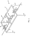
- La figure 2 est une vue de côté illustrant le fonctionnement du dispositif de l'invention.
- Figure 1 schematically illustrates a railroad track equipped with a train washing machine in accordance with the provisions of the invention.
- Figure 2 is a side view illustrating the operation of the device of the invention.
Telle qu'illustrée sur le dessin de la figure 1, la voie ferrée 10 le long de laquelle peut évoluer un véhicule à traction électrique non représenté, comporte classiquement deux rails parallèles 10a et 10b posés sur des traverses solidaires du sol pour constituer le chemin de roulement dudit véhicule. Ces deux rails 10a et 10b sont surmontés d'une ligne aérienne de traction électrique centrale se composant dans le cas présent d'un seul fil de contact 11, éventuellement reliée à une structure-support tel qu'un câble porteur par des fils verticaux dits "pendules" ou par des isolateurs 12. Ce fil de contact ou "caténaire" 11 alimenté en énergie électrique, a pour objet de rester constamment en contact mécanique avec le dispositif de captage d'énergie électrique du véhicule évoluant sur les rails 10a et 10b, constitué à cet effet d'un pantographe animé d'un mouvement ascensionnel permanent pour exercer une pression constante sur ledit fil 11.As illustrated in the drawing in FIG. 1, the
Suivant l'invention, une machine à laver les trains, référencée 20 dans son ensemble, est agencée le long de cette voie ferrée 10, entre les rails 10a, 10b et le fil de contact 11. Elle se compose, disposés successivement dans le sens d'avancement du véhicule et le long de la susdite voie 10 :
- d'une série de brosses verticales 21 qui, disposées en amont et espacées deux par deux pour autoriser entre elles le passage dudit train, sont ajustées en hauteur en fonction des parties latérales du véhicule à nettoyer,
- et d'une série de brosses horizontales 22 qui, disposées en aval, sont animées chacune d'un mouvement pendulaire P pour assurer le nettoyage de l'avant et de l'arrière du véhicule.
- a series of
vertical brushes 21 which, arranged upstream and spaced two by two to allow the passage of said train between them, are adjusted in height as a function of the lateral parts of the vehicle to be cleaned, - and a series of
horizontal brushes 22 which, arranged downstream, are each driven by a pendulum movement P to ensure the cleaning of the front and rear of the vehicle.
Comme on peut le voir sur le dessin de la figure 1, le mouvement pendulaire P des brosses horizontales de lavage 22 pose un problème quant à leur expansion angulaire qui est nécessairement développée de part et d'autre du plan horizontal délimité par le fil de contact 11. Aussi, la longueur de fil de contact 11 disposée au-dessus des rails 10a, 10b et des susdites brosses horizontales 22, a été sectionnée pour être remplacée, conformément au concept fondamental de l'invention, par un rail conducteur 11a.As can be seen in the drawing in FIG. 1, the pendular movement P of the
Comme montré plus en détails sur le dessin de la figure 2, ce rail conducteur 11a est animé d'un mouvement R de pivotement sur lui-même au moyen d'un dispositif d'escamotage 30, entre une position de travail telle qu'illustrée sur le dessin de la figure 2 où ledit rail est disposé dans l'axe du fil de contact 11 et une position de repos non illustrée, où ledit rail est disposé perpendiculairement audit fil de contact 11. Ainsi, dans cette dernière position dite de repos, le rail conducteur 11a se trouve disposé parallèlement aux susdites brosses horizontales de lavage 22 de la machine à laver, de manière à dégager une brèche verticale autorisant le mouvement pendulaire P desdites brosses de part et d'autre du plan horizontal délimité par le fil de contact 11.As shown in more detail in the drawing of FIG. 2, this
Afin d'autoriser le pivotement R en son milieu du rail conducteur 11a, le susdit dispositif d'escamotage 30 est supporté par une structure-support 40 se composant d'un assemblage logique de longerons définissant un cadre horizontal 41 supporté à ses quatre angles par quatre poteaux 42. Les deux poutres latérales 41a du cadre 41 maintiennent en suspension, par l'intermédiaire d'isolateurs 12, les extrémités libres du fil de contact 11 aboutissant à l'intérieur de l'enceinte délimitée par l'ensemble de la structure-support 40. Les deux poutres longitudinales 41b servent d'embase-support au dispositif d'escamotage par pivotement 30 du rail conducteur 11a, constitué à cet effet de deux traverses 31 et 32 montées pivotantes en leur milieu (flèche R) l'une par rapport à l'autre par l'intermédiaire d'un mécanisme de pivotement 33, non représenté car facilement mis en oeuvre par un homme de métier. La première traverse 31, montée fixe sur les deux longerons 41b du cadre 41, est positionnée au-dessus des rails 10a et 10b de la voie ferrée 10 parallèlement aux brosses horizontales de lavage 22, alors que la deuxième traverse 32, montée rotative (fléche R) par rapport à la première, maintient en suspension par l'intermédiaire d'isolateurs 12, le susdit rail conducteur 11a.In order to allow the pivoting R in the middle of the
Il est également possible de prévoir d'autres mouvements de pivotement du susdit rail conducteur 11a à adapter selon la configuration des brosses de lavage 22. Ainsi par exemple, le susdit rail conducteur 11a peut être adapté pour être monté pivotant dans un plan vertical audit fil de contact 11. De même, lorsque ledit rail ne doit s'effacer que devant une seule brosse de lavage, il peut être monté pivotant à l'une de ses extrémités.It is also possible to provide other pivoting movements of the aforesaid
Afin de permettre une meilleure compréhension des dessins, une liste des références avec leurs légendes est ci-après énumérée.
- 10
- Voie ferrée
- 10a,10b
- Rails
- 11
- Fil de contact de la ligne aérienne de traction électrique.
- 11a
- Rail conducteur
- 12
- Isolateurs
- 20
- Machine à laver les trains
- 21
- Brosses verticales de lavage
- 22
- Brosses horizontales de lavage
- 30
- Dispositif d'escamotage du
rail conducteur 11a - 31
- Première traverse fixe
- 32
- Deuxième traverse mobile
- 33
- Mécanisme de pivotement
- 40
- Structure-support
- 41
- Cadre horizontal
- 41a
- Poutres latérales
- 41b
- Poutres Longitudinales
- 42
- Poteaux
- Flèches P
- Mouvement pendulaire des brosses horizontales
- Flèches R
- Mouvement de pivotement du
rail conducteur 11a
- 10
- Track
- 10a, 10b
- Rails
- 11
- Contact wire of the overhead electric traction line.
- 11a
- Conductor rail
- 12
- Insulators
- 20
- Train washing machine
- 21
- Vertical washing brushes
- 22
- Horizontal washing brushes
- 30
- Device for retracting the
conductor rail 11a - 31
- First fixed sleeper
- 32
- Second mobile crossmember
- 33
- Swivel mechanism
- 40
- Support structure
- 41
- Horizontal frame
- 41a
- Lateral beams
- 41b
- Longitudinal beams
- 42
- Posts
- Arrows P
- Pendulum movement of horizontal brushes
- Arrows R
- Pivot movement of the
conductor rail 11a
Claims (4)
- A train washing machine comprising horizontal washing brushes (22) moved by a swinging motion (arrows P), characterised in that said supporting structure (40) of said horizontal washing brushes (22) ensures the support of a retracting device (30) intended to support a conductive rail (11a) allowing to cut off or restore electrical and mechanical continuity of a contact wire (11) of overhaed electrical drive lines crossing longitudinally said train washing machine.
- A train washing machine as claimed in claim 1, characterised in that said conductive rail (11a) is mounted pivotally in its middle (arrow R) in a horizontal plane parallel to said contact wire (11) around a point located in the axis of the said contact wire (11), between a working position in which said rail (11a) is placed in the axis of the contact wire (11) and a resting position in which said rail (11a) is placed perpendicular to said contact wire (11).
- A train washing machine as claimed in claims 1 and 2, characterised in that said supporting structure (40) of the conductive rail (11a) is made of a horizontal frame (41) supported by four posts (42) at its four angles so that the two lateral beams (41a) of the frame (41) hold suspended the free ends of the contact wire (11) ending inside the enclosure of the washing machine, and in that the two longitudinal beams (41b) are used as supporting shoulders for the pivotal retracting device (30) of the conductive rail (11a).
- A train washing machine as claimed in claims 2 and 3, characterised in that said retracting device (30) is made of two crossbeams (31 and 32) pivotally mounted in their middle (arrow R) relative to each other through a pivoting mechanism (33), so that the first crossbeam (31), fixedly mounted on the two longitudinal girders (41b) of the frame (41) is positionned above the rails (10a and 10b) of the railway track (10) parallel to the horizontal washing brushes (22), and the second crossbeam (32), rotatively mounted (arrow R) relative to the first one, holds said conductive rail (11a) suspended through insulators (12).
Applications Claiming Priority (2)
| Application Number | Priority Date | Filing Date | Title |
|---|---|---|---|
| FR9204960 | 1992-04-16 | ||
| FR929204960A FR2690658B1 (en) | 1992-04-16 | 1992-04-16 | PROCESS FOR ESCAMOTATING A CONDUCTIVE RAIL FOR A TRAIN WASHING MACHINE AND DEVICE FOR IMPLEMENTING SAME. |
Publications (2)
| Publication Number | Publication Date |
|---|---|
| EP0566136A1 EP0566136A1 (en) | 1993-10-20 |
| EP0566136B1 true EP0566136B1 (en) | 1996-10-09 |
Family
ID=9429146
Family Applications (1)
| Application Number | Title | Priority Date | Filing Date |
|---|---|---|---|
| EP93106199A Expired - Lifetime EP0566136B1 (en) | 1992-04-16 | 1993-04-16 | Train washing machine |
Country Status (4)
| Country | Link |
|---|---|
| EP (1) | EP0566136B1 (en) |
| AT (1) | ATE143876T1 (en) |
| DE (1) | DE69305214D1 (en) |
| FR (1) | FR2690658B1 (en) |
Family Cites Families (4)
| Publication number | Priority date | Publication date | Assignee | Title |
|---|---|---|---|---|
| US2242692A (en) * | 1938-03-31 | 1941-05-20 | Frank B Yingling | Car washer |
| FR920676A (en) * | 1946-01-25 | 1947-04-15 | Kummler & Matter Ag | Drop-off for trolley buses |
| SU1119888A1 (en) * | 1983-07-27 | 1984-10-23 | Ленинградский Ордена Ленина Метрополитен Им.В.И.Ленина | Arrangement for washing face surfaces of vehicles |
| FR2666280B1 (en) * | 1990-09-04 | 1993-04-30 | Sncf | AERIAL POWER SUPPLY DEVICE FOR RAIL VEHICLES, COMPRISING A RIGID RETRACTABLE CONDUCTOR, AND SUPPLY LINE OR LINE ASSEMBLY USING AT LEAST SUCH A DEVICE. |
-
1992
- 1992-04-16 FR FR929204960A patent/FR2690658B1/en not_active Expired - Fee Related
-
1993
- 1993-04-16 EP EP93106199A patent/EP0566136B1/en not_active Expired - Lifetime
- 1993-04-16 AT AT93106199T patent/ATE143876T1/en active
- 1993-04-16 DE DE69305214T patent/DE69305214D1/en not_active Expired - Lifetime
Also Published As
| Publication number | Publication date |
|---|---|
| FR2690658A1 (en) | 1993-11-05 |
| FR2690658B1 (en) | 1994-06-17 |
| DE69305214D1 (en) | 1996-11-14 |
| ATE143876T1 (en) | 1996-10-15 |
| EP0566136A1 (en) | 1993-10-20 |
Similar Documents
| Publication | Publication Date | Title |
|---|---|---|
| JP6457514B2 (en) | Contact device, charging contact unit, and method for electrically connecting a vehicle to a charging station | |
| EP0962353B1 (en) | Ground feeding system for electrical vehicle and associated vehicle | |
| EP0130947A1 (en) | Powered suspended vehicle | |
| FR2942750A1 (en) | AIR ASSEMBLY FOR PROVIDING ELECTRICAL POWER TO A GROUND VEHICLE. | |
| CA2780853C (en) | Energy charging device for a vehicle | |
| FR2762810A1 (en) | POWER SUPPLY DEVICE OF ELECTRIC VEHICLE WITH GROUNDING | |
| EP2345554B1 (en) | Power-recharging device for an item of power-storage equipment on board a vehicle | |
| EP1558458B1 (en) | Permanent control device for the grounding of an electric public transport vehicle running on tyres and which is self-guided | |
| EP2088025B1 (en) | Ground electricity supply circuit, in particular for a tram | |
| EP0566136B1 (en) | Train washing machine | |
| JP2016043875A (en) | Snow removal brush, vehicle, combination vehicle, and track transportation system | |
| FR2521499A1 (en) | CURRENT COLLECTOR APPARATUS APPLICABLE TO A TRANSPORT VEHICLE SYSTEM | |
| FR2749439A1 (en) | CONTACT AND SUSPENSION HEAD FOR SHORT-CIRCUIT POLE OF A CATENARY | |
| EP0349390B1 (en) | Device for the collective underground transport of passengers using automatic actuation by independent traction carriages, especially using propulsion by a linear motor | |
| FR3059949A1 (en) | CATENARY ELECTRICAL CONNECTOR, AND CATALYAN ASSEMBLY OF A TRACK CATENARY AND CATALOG INCLUDING SUCH A CONNECTOR | |
| EP0474547A1 (en) | Overhead electrical power supply device for railway vehicles, comprising a retractable rigid conductor, and supply line or line assembly using at least such a device | |
| FR2825666A1 (en) | Direct electrical supply system, for urban transport rail vehicles, feeding low voltage power to rails which is picked up by current collectors associated with wheels electrically isolated from chassis | |
| CH619656A5 (en) | Handling device comprising an overhead track | |
| FR2669868A1 (en) | AERIAL ELECTRIC POWER SUPPLY DEVICE FOR RAILWAY VEHICLES HORIZONTALLY FLEXIBLE CONDUCTOR AND ELECTRIC POWER LINE COMPRISING AT LEAST ONE SUCH DEVICE. | |
| CA3118662A1 (en) | Cable guiding device for urban or peri-urban aerial cableway system | |
| WO2006042922A1 (en) | Cross arrangement of two guide rails that are part of a ground-based electrical energy capture system for a vehicle | |
| FR3104119A1 (en) | PUBLIC TRANSPORT SYSTEM | |
| FR2966397A1 (en) | Electrical energy recharging device for e.g. battery of tramway, has flexible metal conductive material interposed between surfaces to form surface contact for assuring transfer of energy between energy collector and supply device | |
| EP3842275A1 (en) | Device for capturing electrical energy for a vehicle, in particular a railway vehicle, and vehicle, in particular a railway vehicle, including such a device | |
| FR2677941A1 (en) | Checking vehicle for measuring the height and offset of the contact wire or wires of electric aerial (overhead) contact lines on railway tracks |
Legal Events
| Date | Code | Title | Description |
|---|---|---|---|
| PUAI | Public reference made under article 153(3) epc to a published international application that has entered the european phase |
Free format text: ORIGINAL CODE: 0009012 |
|
| AK | Designated contracting states |
Kind code of ref document: A1 Designated state(s): AT BE CH DE DK ES GB GR IT LI LU MC NL PT SE |
|
| 17P | Request for examination filed |
Effective date: 19940328 |
|
| 17Q | First examination report despatched |
Effective date: 19950316 |
|
| GRAG | Despatch of communication of intention to grant |
Free format text: ORIGINAL CODE: EPIDOS AGRA |
|
| GRAH | Despatch of communication of intention to grant a patent |
Free format text: ORIGINAL CODE: EPIDOS IGRA |
|
| GRAH | Despatch of communication of intention to grant a patent |
Free format text: ORIGINAL CODE: EPIDOS IGRA |
|
| GRAA | (expected) grant |
Free format text: ORIGINAL CODE: 0009210 |
|
| AK | Designated contracting states |
Kind code of ref document: B1 Designated state(s): AT BE CH DE DK ES GB GR IT LI LU MC NL PT SE |
|
| PG25 | Lapsed in a contracting state [announced via postgrant information from national office to epo] |
Ref country code: NL Free format text: LAPSE BECAUSE OF FAILURE TO SUBMIT A TRANSLATION OF THE DESCRIPTION OR TO PAY THE FEE WITHIN THE PRESCRIBED TIME-LIMIT Effective date: 19961009 Ref country code: GR Free format text: LAPSE BECAUSE OF FAILURE TO SUBMIT A TRANSLATION OF THE DESCRIPTION OR TO PAY THE FEE WITHIN THE PRESCRIBED TIME-LIMIT Effective date: 19961009 Ref country code: ES Free format text: THE PATENT HAS BEEN ANNULLED BY A DECISION OF A NATIONAL AUTHORITY Effective date: 19961009 Ref country code: DK Effective date: 19961009 Ref country code: AT Effective date: 19961009 |
|
| REF | Corresponds to: |
Ref document number: 143876 Country of ref document: AT Date of ref document: 19961015 Kind code of ref document: T |
|
| REF | Corresponds to: |
Ref document number: 69305214 Country of ref document: DE Date of ref document: 19961114 |
|
| ITF | It: translation for a ep patent filed |
Owner name: ORGANIZZAZIONE D'AGOSTINI |
|
| PG25 | Lapsed in a contracting state [announced via postgrant information from national office to epo] |
Ref country code: SE Effective date: 19970109 Ref country code: PT Effective date: 19970109 |
|
| PG25 | Lapsed in a contracting state [announced via postgrant information from national office to epo] |
Ref country code: DE Effective date: 19970110 |
|
| GBT | Gb: translation of ep patent filed (gb section 77(6)(a)/1977) |
Effective date: 19970109 |
|
| NLV1 | Nl: lapsed or annulled due to failure to fulfill the requirements of art. 29p and 29m of the patents act | ||
| PG25 | Lapsed in a contracting state [announced via postgrant information from national office to epo] |
Ref country code: LU Free format text: LAPSE BECAUSE OF NON-PAYMENT OF DUE FEES Effective date: 19970430 Ref country code: LI Free format text: LAPSE BECAUSE OF NON-PAYMENT OF DUE FEES Effective date: 19970430 Ref country code: CH Free format text: LAPSE BECAUSE OF NON-PAYMENT OF DUE FEES Effective date: 19970430 |
|
| PLBE | No opposition filed within time limit |
Free format text: ORIGINAL CODE: 0009261 |
|
| STAA | Information on the status of an ep patent application or granted ep patent |
Free format text: STATUS: NO OPPOSITION FILED WITHIN TIME LIMIT |
|
| 26N | No opposition filed | ||
| PG25 | Lapsed in a contracting state [announced via postgrant information from national office to epo] |
Ref country code: MC Effective date: 19971031 |
|
| REG | Reference to a national code |
Ref country code: CH Ref legal event code: PL |
|
| PGFP | Annual fee paid to national office [announced via postgrant information from national office to epo] |
Ref country code: GB Payment date: 19990428 Year of fee payment: 7 |
|
| PGFP | Annual fee paid to national office [announced via postgrant information from national office to epo] |
Ref country code: BE Payment date: 19990429 Year of fee payment: 7 |
|
| PG25 | Lapsed in a contracting state [announced via postgrant information from national office to epo] |
Ref country code: GB Free format text: LAPSE BECAUSE OF NON-PAYMENT OF DUE FEES Effective date: 20000416 |
|
| PG25 | Lapsed in a contracting state [announced via postgrant information from national office to epo] |
Ref country code: BE Free format text: LAPSE BECAUSE OF NON-PAYMENT OF DUE FEES Effective date: 20000430 |
|
| BERE | Be: lapsed |
Owner name: SOC. DES ETS ROGER BRILLIE S.A. Effective date: 20000430 Owner name: S.A. S.C.L.E. Effective date: 20000430 |
|
| GBPC | Gb: european patent ceased through non-payment of renewal fee |
Effective date: 20000416 |
|
| PG25 | Lapsed in a contracting state [announced via postgrant information from national office to epo] |
Ref country code: IT Free format text: LAPSE BECAUSE OF NON-PAYMENT OF DUE FEES;WARNING: LAPSES OF ITALIAN PATENTS WITH EFFECTIVE DATE BEFORE 2007 MAY HAVE OCCURRED AT ANY TIME BEFORE 2007. THE CORRECT EFFECTIVE DATE MAY BE DIFFERENT FROM THE ONE RECORDED. Effective date: 20050416 |