EP0566136B1 - Schienenfahrzeugwaschmaschine - Google Patents
Schienenfahrzeugwaschmaschine Download PDFInfo
- Publication number
- EP0566136B1 EP0566136B1 EP93106199A EP93106199A EP0566136B1 EP 0566136 B1 EP0566136 B1 EP 0566136B1 EP 93106199 A EP93106199 A EP 93106199A EP 93106199 A EP93106199 A EP 93106199A EP 0566136 B1 EP0566136 B1 EP 0566136B1
- Authority
- EP
- European Patent Office
- Prior art keywords
- contact wire
- washing machine
- rail
- horizontal
- train
- Prior art date
- Legal status (The legal status is an assumption and is not a legal conclusion. Google has not performed a legal analysis and makes no representation as to the accuracy of the status listed.)
- Expired - Lifetime
Links
Images

Classifications
-
- B—PERFORMING OPERATIONS; TRANSPORTING
- B60—VEHICLES IN GENERAL
- B60M—POWER SUPPLY LINES, AND DEVICES ALONG RAILS, FOR ELECTRICALLY- PROPELLED VEHICLES
- B60M1/00—Power supply lines for contact with collector on vehicle
- B60M1/12—Trolley lines; Accessories therefor
-
- B—PERFORMING OPERATIONS; TRANSPORTING
- B60—VEHICLES IN GENERAL
- B60S—SERVICING, CLEANING, REPAIRING, SUPPORTING, LIFTING, OR MANOEUVRING OF VEHICLES, NOT OTHERWISE PROVIDED FOR
- B60S3/00—Vehicle cleaning apparatus not integral with vehicles
- B60S3/006—Vehicle cleaning apparatus not integral with vehicles specially adapted for railway vehicles
-
- B—PERFORMING OPERATIONS; TRANSPORTING
- B60—VEHICLES IN GENERAL
- B60S—SERVICING, CLEANING, REPAIRING, SUPPORTING, LIFTING, OR MANOEUVRING OF VEHICLES, NOT OTHERWISE PROVIDED FOR
- B60S3/00—Vehicle cleaning apparatus not integral with vehicles
- B60S3/04—Vehicle cleaning apparatus not integral with vehicles for exteriors of land vehicles
- B60S3/06—Vehicle cleaning apparatus not integral with vehicles for exteriors of land vehicles with rotary bodies contacting the vehicle
Definitions
- the present invention relates to a train washing machine according to the preamble, of Claim 1, suitable for being placed on tracks equipped with overhead electric traction lines.
- these overhead electrical traction lines include one or more conductive contact wires which, suspended from a support structure by means of insulators, must remain constantly in contact with the current taking device of the electric locomotive fitted for this purpose with a pantograph.
- the efficiency of the collection of electrical energy by the locomotive moving along the railway track is essentially dependent on the regularity of the contact plane between the top of the conductor wires and the pantograph.
- the overhead electric traction line will be assumed to have only one contact wire.
- This contact wire is a cause for worrying discomfort for the installation of a train washing machine along an electrified track, in particular to allow the rocking movements of the horizontal washing brushes .
- the first envisaged solution most used to date has been the removal of said bulky contact wire above the portion of track comprising the washing machine.
- the absence of this contact wire leads to a break in the electrical charge since the trains must then be pushed or pulled by a locotractor or a cable on a capstan, to be transported inside the washing enclosure of the machine.
- the removal of this contact wire also causes a mechanical break in the contact wire, for guiding the pantograph of the electric locomotive, pantograph which then risks deploying dangerously under the effect of its upward movement delivered to itself. even.
- said conductor rail is pivotally mounted around a point disposed in the axis of the above contact wire, between a working position where said rail is disposed in the axis of the contact wire to ensure electrical continuity and mechanical of the latter through the washing machine and, a rest position, or said rail is disposed perpendicular to said contact wire, so as to release at least one vertical gap in the mechanical continuity of the contact wire inside of the washing machine in order to allow an angular expansion of the horizontal washing brushes on either side of the horizontal plane delimited by the contact wire.
- the electric locomotive can then be routed along the railroad track inside said washing machine, without an electrical break for the energy capture necessary for its traction and without mechanical break for the guidance of its pantograph.
- the rail is pivoted to a rest position where it is positioned perpendicular to the contact wire so as to establish an electrical break in the circuit in the washing machine and to clear a vertical gap allowing the angular movements of the horizontal washing brushes on either side of the horizontal plane delimited by the contact wire.
- the invention relates to a washing machine equipped with a device implementing such a method of retraction by pivoting a conductor rail.
- the above device consists of a conductive rail which, disposed in the washing machine, is supported by means of a pivoting mechanism to the support structure of the contact wire of the overhead traction line electric on both sides of the washing machine.
- the railroad track 10 along which an electric traction vehicle (not shown) can move conventionally comprises two parallel rails 10a and 10b placed on sleepers integral with the ground to constitute the path of rolling of said vehicle.
- These two rails 10a and 10b are surmounted by an overhead central electric traction line consisting in the present case of a single contact wire 11, possibly connected to a support structure such as a carrying cable by so-called vertical wires "pendulums" or by insulators 12.
- this contact or "catenary" wire 11 supplied with electrical energy is to remain in constant mechanical contact with the vehicle's electrical energy collection device operating on the rails 10a and 10b , made up for this purpose of a pantograph animated by a permanent upward movement to exercise a constant pressure on said wire 11.
- the pendular movement P of the horizontal washing brushes 22 poses a problem as regards their angular expansion which is necessarily developed on either side of the horizontal plane delimited by the contact wire 11.
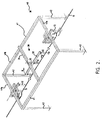
- the length of contact wire 11 disposed above the rails 10a, 10b and the above horizontal brushes 22, has been cut to be replaced, in accordance with the fundamental concept of the invention, by a conductive rail 11a.
- this conductive rail 11a is driven by a movement R of pivoting on itself by means of a retracting device 30, between a working position as illustrated in the drawing of Figure 2 where said rail is arranged in the axis of the contact wire 11 and a rest position not shown, where said rail is arranged perpendicular to said contact wire 11.
- the conductive rail 11a is arranged parallel to the above horizontal washing brushes 22 of the washing machine, so as to release a vertical gap allowing the pendular movement P of said brushes on either side of the horizontal plane delimited by the wire. contact 11.
- the aforesaid retracting device 30 is supported by a support structure 40 consisting of a logical assembly of side members defining a horizontal frame 41 supported at its four angles by four posts 42.
- the two lateral beams 41a of the frame 41 maintain in suspension, by means of insulators 12, the free ends of the contact wire 11 terminating inside the enclosure delimited by the assembly of the support structure 40.
- the two longitudinal beams 41b serve as a support base for the retractable device by pivoting 30 of the conductor rail 11a, constituted for this purpose by two cross members 31 and 32 mounted pivoting in their middle (arrow R) relative to each other by means of a pivoting mechanism 33, not shown because it is easily implemented by a person skilled in the art.
- the first cross member 31, fixedly mounted on the two longitudinal members 41b of the frame 41 is positioned above the rails 10a and 10b of the railroad track 10 parallel to the horizontal washing brushes 22, while the second cross member 32, rotatably mounted (arrow) R) relative to the first, maintained in suspension by means of insulators 12, the aforesaid conductive rail 11a.
- the aforesaid conductive rail 11a can be adapted to be pivotally mounted in a vertical plane to said wire. 11. In the same way, when said rail should only be erased before a single washing brush, it can be pivotally mounted at one of its ends.
Landscapes
- Engineering & Computer Science (AREA)
- Mechanical Engineering (AREA)
- Current-Collector Devices For Electrically Propelled Vehicles (AREA)
- Vehicle Cleaning, Maintenance, Repair, Refitting, And Outriggers (AREA)
- Processing Of Solid Wastes (AREA)
Claims (4)
- Waschvorrichtung für Züge bestehend aus waagrechten, hin- und herpendelden (Pfeil P) Waschbürsten (22) GEKENNZEICHNET DADURCH, DAß die Abstützstruktur (40) der oben genannten waagrechten Waschbürsten (22) eine wegschwenkbare Vorrichtung (30) stützt, die eine Leitschiene (11a) trägt, deren Aufgabe es ist, die elektrische und die mechanische Kontinuität des Kontaktdrahtes (11) einer oberirdischen elektrischen Förderungsleitung zu gewähren, die die genannte Waschvorrichtung längs durchquert.
- Waschvorrichtung nach dem Anspruch 1 GEKENNZEICHNET DADURCH, DAß die genannte Leitschiene (11a) auf einer waagrechten, zu dem Kontaktdraht (11) parallelen Ebene in ihrer Mitte schwenkbar (Pfeil R) um einen Punkt in der Fluchtlinie des Kontaktdrahtes angebracht ist, und zwar (11) zwischen einer Arbeitsstellung, wo die genannte Schiene (11a) sich in der Fluchtlinie des Kontaktdrahtes (11), und einer Ruhestellung, wo die genannte Schiene (11a), sich senkrecht zu dem Kontaktdraht (11) befindet.
- Waschvorrichtung nach den Ansprüchen 1 und 2 GEKENNZEICHNET DADURCH, DAß die genannte Stützstruktur (40) der Leitschiene (11a) aus einem an seinen vier Ecken durch vier Pfähle gestützen Rahmen (41) besteht, so daß die zwei Querbalken (41a) des Rahmens (41) eine Aufhängung für die in die Waschvorrichtung führenden freien Extremitäten des Kontaktdrahtes (11) bilden, und daß die zwei Längsbalken (41b) als Stützfläche für die wegschwenkbare Vorrichtung (30) der Leitschiene dienen.
- Waschvorrichtung nach Ansprüchen 2 und 3 GEKENNZEICHNET DADURCH, DAß die genannte wegschwenkbare Vorrichtung (30) aus zwei durch eine Schwenkvorrichtung (33) in ihrer Mitte zueinander schwenkbaren (Pfeil R) Querleisten (31 und 32) besteht, so daß die erste Querleiste (31), die fest auf den zwei Längsbalken (41b) des Rahmens (41) angebracht ist, sich oberhalb der Bahnschienen (10a und 10b) parallel zu den waagrechten Waschbürsten (22) befindet, und daß die zweite Leiste (32), die schwenkbar (Pfeil R) im Verhältnis zu der ersten Leiste angebracht ist, durch Isolatoren (12) eine Aufhängung für die genannte Leitschiene (11a) bildet.
Applications Claiming Priority (2)
| Application Number | Priority Date | Filing Date | Title |
|---|---|---|---|
| FR9204960 | 1992-04-16 | ||
| FR929204960A FR2690658B1 (fr) | 1992-04-16 | 1992-04-16 | Procede d'escamotage d'un rail conducteur pour machine a laver les trains et dispositif permettant de le mettre en óoeuvre. |
Publications (2)
| Publication Number | Publication Date |
|---|---|
| EP0566136A1 EP0566136A1 (de) | 1993-10-20 |
| EP0566136B1 true EP0566136B1 (de) | 1996-10-09 |
Family
ID=9429146
Family Applications (1)
| Application Number | Title | Priority Date | Filing Date |
|---|---|---|---|
| EP93106199A Expired - Lifetime EP0566136B1 (de) | 1992-04-16 | 1993-04-16 | Schienenfahrzeugwaschmaschine |
Country Status (4)
| Country | Link |
|---|---|
| EP (1) | EP0566136B1 (de) |
| AT (1) | ATE143876T1 (de) |
| DE (1) | DE69305214D1 (de) |
| FR (1) | FR2690658B1 (de) |
Families Citing this family (1)
| Publication number | Priority date | Publication date | Assignee | Title |
|---|---|---|---|---|
| CN112109668A (zh) * | 2020-09-14 | 2020-12-22 | 山东泰安煤矿机械有限公司 | 用于列车车厢的余物清除装置、方法和及其应用 |
Family Cites Families (4)
| Publication number | Priority date | Publication date | Assignee | Title |
|---|---|---|---|---|
| US2242692A (en) * | 1938-03-31 | 1941-05-20 | Frank B Yingling | Car washer |
| FR920676A (fr) * | 1946-01-25 | 1947-04-15 | Kummler & Matter Ag | Dépôt pour des omnibus à trolley |
| SU1119888A1 (ru) * | 1983-07-27 | 1984-10-23 | Ленинградский Ордена Ленина Метрополитен Им.В.И.Ленина | Устройство дл мойки лобовых поверхностей транспортных средств |
| FR2666280B1 (fr) * | 1990-09-04 | 1993-04-30 | Sncf | Dispositif d'alimentation electrique aerienne de vehicules ferroviaires, comportant un conducteur rigide escamotable, et ligne d'alimentation ou ensemble de lignes utilisant au moins un tel dispositif. |
-
1992
- 1992-04-16 FR FR929204960A patent/FR2690658B1/fr not_active Expired - Fee Related
-
1993
- 1993-04-16 EP EP93106199A patent/EP0566136B1/de not_active Expired - Lifetime
- 1993-04-16 DE DE69305214T patent/DE69305214D1/de not_active Expired - Lifetime
- 1993-04-16 AT AT93106199T patent/ATE143876T1/de active
Also Published As
| Publication number | Publication date |
|---|---|
| FR2690658A1 (fr) | 1993-11-05 |
| DE69305214D1 (de) | 1996-11-14 |
| ATE143876T1 (de) | 1996-10-15 |
| EP0566136A1 (de) | 1993-10-20 |
| FR2690658B1 (fr) | 1994-06-17 |
Similar Documents
| Publication | Publication Date | Title |
|---|---|---|
| JP6457515B2 (ja) | 接触装置、充電接触ユニット、及び、車両を充電ステーションに電気的に接続する方法 | |
| EP0962353B1 (de) | Boden-Stromzuführungssystem für ein Elektrofahrzeug und Fahrzeug dafür | |
| FR2942750A1 (fr) | Ensemble aerien pour la fourniture d'energie electrique a un vehicule terrestre. | |
| FR2762810A1 (fr) | Dispositif d'alimentation par le sol de vehicule electrique avec mise a la terre | |
| EP2535219B1 (de) | Energieaufladevorrichtung für ein Fahrzeug | |
| EP2345554B1 (de) | Energieaufladevorrichtung für ein Energiespeichergerät an Bord eines Fahrzeugs | |
| EP1558458B1 (de) | Vorrichtung zur permanenten kontrolle von der erdung eines elektrischen öffentlichen selbststeuernden transportfahrzeuges auf reifen | |
| EP0566136B1 (de) | Schienenfahrzeugwaschmaschine | |
| FR2521499A1 (fr) | Appareil collecteur de courant applicable a un systeme a vehicules de transport | |
| FR2552629A1 (fr) | Dispositif pour assommer par decharge electrique des animaux destines a l'abattage | |
| EP0349390B1 (de) | Einrichtung vom Typ U-Bahn für den gemeinschaftlichen Transport von Passagieren mit automatischen Antrieb durch unabhängige Zugwagen, insb. unter Verwendung des Antriebs durch einen Linearmotor | |
| FR3059949A1 (fr) | Connecteur electrique de catenaire, et ensemble d'une catenaire de voie et d'une catenaire escamotable comprenant un tel connecteur | |
| FR2669868A1 (fr) | Dispositif d'alimentation electrique aerienne de vehicules ferroviaires, a conducteur souple et escamotable horizontalement, et ligne d'alimentation electrique comportant au moins un tel dispositif. | |
| EP0474547A1 (de) | Oberirdische elektrische Versorgungsvorrichtung für Eisenbahnfahrzeuge mit einer steifen ausklappbaren Leiter und Fahrleitung oder Fahrleitungskomplex mit mindestens einer solchen Vorrichtung | |
| FR2825666A1 (fr) | Systeme d'alimentation directe en energie electrique d'un vehicule ferroviaire et voie ferree correspondante | |
| CH619656A5 (en) | Handling device comprising an overhead track | |
| WO2006042922A1 (fr) | Croisement de deux rails de guidage faisant partie d'un ensemble de captage au sol d'energie electrique pour un vehicule. | |
| EP4520585B1 (de) | Vorrichtung zur wartung eines oberleitungsdrahtes | |
| EP3842275B1 (de) | Elektrische energieaufnahmevorrichtung für ein fahrzeug, insbesondere ein schienenfahrzeug, und fahrzeug, insbesondere schienenfahrzeug, das eine solchen vorrichtung umfasst | |
| KR100728467B1 (ko) | 건널목의 이동식 전차선 | |
| CN218768914U (zh) | 一种集电弓绝缘子清理装置 | |
| FR2966397A1 (fr) | Dispositif de recharge en energie pour un equipement de stockage d'energie embarque a bord d'un vehicule | |
| CN113085670B (zh) | 一种装卸线移动接触悬挂的自动接地装置 | |
| CH619403A5 (de) | ||
| US677262A (en) | Trolley. |
Legal Events
| Date | Code | Title | Description |
|---|---|---|---|
| PUAI | Public reference made under article 153(3) epc to a published international application that has entered the european phase |
Free format text: ORIGINAL CODE: 0009012 |
|
| AK | Designated contracting states |
Kind code of ref document: A1 Designated state(s): AT BE CH DE DK ES GB GR IT LI LU MC NL PT SE |
|
| 17P | Request for examination filed |
Effective date: 19940328 |
|
| 17Q | First examination report despatched |
Effective date: 19950316 |
|
| GRAG | Despatch of communication of intention to grant |
Free format text: ORIGINAL CODE: EPIDOS AGRA |
|
| GRAH | Despatch of communication of intention to grant a patent |
Free format text: ORIGINAL CODE: EPIDOS IGRA |
|
| GRAH | Despatch of communication of intention to grant a patent |
Free format text: ORIGINAL CODE: EPIDOS IGRA |
|
| GRAA | (expected) grant |
Free format text: ORIGINAL CODE: 0009210 |
|
| AK | Designated contracting states |
Kind code of ref document: B1 Designated state(s): AT BE CH DE DK ES GB GR IT LI LU MC NL PT SE |
|
| PG25 | Lapsed in a contracting state [announced via postgrant information from national office to epo] |
Ref country code: NL Free format text: LAPSE BECAUSE OF FAILURE TO SUBMIT A TRANSLATION OF THE DESCRIPTION OR TO PAY THE FEE WITHIN THE PRESCRIBED TIME-LIMIT Effective date: 19961009 Ref country code: GR Free format text: LAPSE BECAUSE OF FAILURE TO SUBMIT A TRANSLATION OF THE DESCRIPTION OR TO PAY THE FEE WITHIN THE PRESCRIBED TIME-LIMIT Effective date: 19961009 Ref country code: ES Free format text: THE PATENT HAS BEEN ANNULLED BY A DECISION OF A NATIONAL AUTHORITY Effective date: 19961009 Ref country code: DK Effective date: 19961009 Ref country code: AT Effective date: 19961009 |
|
| REF | Corresponds to: |
Ref document number: 143876 Country of ref document: AT Date of ref document: 19961015 Kind code of ref document: T |
|
| REF | Corresponds to: |
Ref document number: 69305214 Country of ref document: DE Date of ref document: 19961114 |
|
| ITF | It: translation for a ep patent filed | ||
| PG25 | Lapsed in a contracting state [announced via postgrant information from national office to epo] |
Ref country code: SE Effective date: 19970109 Ref country code: PT Effective date: 19970109 |
|
| PG25 | Lapsed in a contracting state [announced via postgrant information from national office to epo] |
Ref country code: DE Effective date: 19970110 |
|
| GBT | Gb: translation of ep patent filed (gb section 77(6)(a)/1977) |
Effective date: 19970109 |
|
| NLV1 | Nl: lapsed or annulled due to failure to fulfill the requirements of art. 29p and 29m of the patents act | ||
| PG25 | Lapsed in a contracting state [announced via postgrant information from national office to epo] |
Ref country code: LU Free format text: LAPSE BECAUSE OF NON-PAYMENT OF DUE FEES Effective date: 19970430 Ref country code: LI Free format text: LAPSE BECAUSE OF NON-PAYMENT OF DUE FEES Effective date: 19970430 Ref country code: CH Free format text: LAPSE BECAUSE OF NON-PAYMENT OF DUE FEES Effective date: 19970430 |
|
| PLBE | No opposition filed within time limit |
Free format text: ORIGINAL CODE: 0009261 |
|
| 26N | No opposition filed | ||
| PG25 | Lapsed in a contracting state [announced via postgrant information from national office to epo] |
Ref country code: MC Effective date: 19971031 |
|
| REG | Reference to a national code |
Ref country code: CH Ref legal event code: PL |
|
| PGFP | Annual fee paid to national office [announced via postgrant information from national office to epo] |
Ref country code: GB Payment date: 19990428 Year of fee payment: 7 |
|
| PGFP | Annual fee paid to national office [announced via postgrant information from national office to epo] |
Ref country code: BE Payment date: 19990429 Year of fee payment: 7 |
|
| PG25 | Lapsed in a contracting state [announced via postgrant information from national office to epo] |
Ref country code: GB Free format text: LAPSE BECAUSE OF NON-PAYMENT OF DUE FEES Effective date: 20000416 |
|
| PG25 | Lapsed in a contracting state [announced via postgrant information from national office to epo] |
Ref country code: BE Free format text: LAPSE BECAUSE OF NON-PAYMENT OF DUE FEES Effective date: 20000430 |
|
| BERE | Be: lapsed |
Owner name: SOC. DES ETS ROGER BRILLIE S.A. Effective date: 20000430 Owner name: S.A. S.C.L.E. Effective date: 20000430 |
|
| GBPC | Gb: european patent ceased through non-payment of renewal fee |
Effective date: 20000416 |
|
| PG25 | Lapsed in a contracting state [announced via postgrant information from national office to epo] |
Ref country code: IT Free format text: LAPSE BECAUSE OF NON-PAYMENT OF DUE FEES;WARNING: LAPSES OF ITALIAN PATENTS WITH EFFECTIVE DATE BEFORE 2007 MAY HAVE OCCURRED AT ANY TIME BEFORE 2007. THE CORRECT EFFECTIVE DATE MAY BE DIFFERENT FROM THE ONE RECORDED. Effective date: 20050416 |