EP0565973B1 - Dispositif d'ancrage - Google Patents
Dispositif d'ancrage Download PDFInfo
- Publication number
- EP0565973B1 EP0565973B1 EP93105542A EP93105542A EP0565973B1 EP 0565973 B1 EP0565973 B1 EP 0565973B1 EP 93105542 A EP93105542 A EP 93105542A EP 93105542 A EP93105542 A EP 93105542A EP 0565973 B1 EP0565973 B1 EP 0565973B1
- Authority
- EP
- European Patent Office
- Prior art keywords
- bolt
- carrier
- crossbar
- region
- locking
- Prior art date
- Legal status (The legal status is an assumption and is not a legal conclusion. Google has not performed a legal analysis and makes no representation as to the accuracy of the status listed.)
- Expired - Lifetime
Links
- 238000004873 anchoring Methods 0.000 claims 4
- 230000000977 initiatory effect Effects 0.000 claims 1
- 238000010276 construction Methods 0.000 description 1
- 238000006073 displacement reaction Methods 0.000 description 1
- 238000000034 method Methods 0.000 description 1
- 238000005192 partition Methods 0.000 description 1
- 230000002265 prevention Effects 0.000 description 1
- 230000007704 transition Effects 0.000 description 1
Images


Classifications
-
- B—PERFORMING OPERATIONS; TRANSPORTING
- B64—AIRCRAFT; AVIATION; COSMONAUTICS
- B64D—EQUIPMENT FOR FITTING IN OR TO AIRCRAFT; FLIGHT SUITS; PARACHUTES; ARRANGEMENT OR MOUNTING OF POWER PLANTS OR PROPULSION TRANSMISSIONS IN AIRCRAFT
- B64D9/00—Equipment for handling freight; Equipment for facilitating passenger embarkation or the like
- B64D9/003—Devices for retaining pallets or freight containers
-
- B—PERFORMING OPERATIONS; TRANSPORTING
- B64—AIRCRAFT; AVIATION; COSMONAUTICS
- B64D—EQUIPMENT FOR FITTING IN OR TO AIRCRAFT; FLIGHT SUITS; PARACHUTES; ARRANGEMENT OR MOUNTING OF POWER PLANTS OR PROPULSION TRANSMISSIONS IN AIRCRAFT
- B64D11/00—Passenger or crew accommodation; Flight-deck installations not otherwise provided for
- B64D11/06—Arrangements of seats, or adaptations or details specially adapted for aircraft seats
- B64D11/0696—Means for fastening seats to floors, e.g. to floor rails
Definitions
- the invention relates to a device for locking components for interiors for aircraft, which fixes the components in seat rails, which are arranged in the region of an aircraft floor and which has at least one locking element which is rotatably guided in a carrier and has at least one projection which in a locked positioning engages behind an upper limiting web of the seat rail and in which the locking element is designed as a bolt, which is connected in the region of its end facing away from the carrier with a cross-member which connects the bolt to form two projections projecting laterally, the bolt has an external thread for locking relative to the carrier and that at least one bolt is arranged between two positioning elements which extend substantially parallel to the bolt and can be inserted into receptacle extensions of the seat rail
- Such devices are used, for example, to connect seats and other furnishings in the area of passenger aircraft, or floor covering elements or cargo compartment partitions in the area of cargo aircraft, to the aircraft floor.
- the known devices are not sufficiently capable of ensuring simple handling, space-saving dimensioning and reliable fixing of the components in the direction of all xyz coordinates.
- a device for locking components for aircraft interiors is already known.
- the components are fixed in the area of seat rails, which are arranged in the area of an aircraft floor.
- the device has at least one locking element which is rotatably guided in a carrier.
- the locking element is designed as a bolt which is connected in the region of its end facing away from the carrier with a cross-member which laterally projects over the bolt to form two projections.
- two bolts provided with projections one behind the other in the direction of the course of the seat rails.
- US-A-4 449 875 Another device for fixing components in the area of seat rails of aircraft is known from US-A-4 449 875.
- a carrier two bolts provided with projections arranged one behind the other.
- the bolts can be inserted with the projections into recesses in the seat rail and are moved together with the carrier in a longitudinal direction of the seat rail. After moving, the projections are arranged below a narrowed slot in the seat rail and can be braced relative to the seat rail in order to fix the carrier.
- the object of the present invention is to construct a device of the type mentioned in the introduction in such a way that universal usability with a small dimension and sufficient functionality is ensured.
- this object is achieved in that the positioning elements are provided with side recesses which face the crossbeam and which receive the projections in an unlocked position.
- the combination of the bolt and the crossmember makes it possible in a simple manner to lock in the region of both boundary webs of the seat rail by means of a rotary movement. In this way, a tilt-proof fixation is achieved.
- the positioning elements fix the aircraft in the x and y directions before the locking is carried out.
- the receptacle extensions are provided in the area of the seat rail at a predetermined grid spacing, for example in a grid of inches.
- the positioning elements are provided with side recesses which face the cross member and which receive the projections in an unlocked position.
- a defined unlocking position is provided in that a stop surface for limiting the pivoting movement of the crossbar is arranged in the area of the side recess.
- the cross member have a width which is slightly less than an extension of a connecting groove which transitions the receiving extensions into one another transversely to a longitudinal direction of the Seat rail is.
- locking pins are provided for fixing the positioning elements relative to the component, which extend essentially parallel to the bolt.
- a compact, yet easy to use embodiment can be constructed in that three Positioning elements and two locking elements are alternately arranged one behind the other in the direction of a longitudinal extension of the seat rail.
- the carrier be designed as a base element of the component.
- the carrier is designed as a base plate which extends essentially parallel to a lower boundary of the component.
- the carrier is designed as a base plate which extends essentially parallel to a lower boundary of the component.
- all that is required in the base region of the component is to provide holes for the bolts to pass through and, if necessary, additional holes for inserting the locking pins.
- the device can thus either be connected to the component before assembly and used together with the component in the seat rail, or first inserted and locked separately in the seat rail and subsequently connected to the component. With the latter method of operation, only the nuts need to be tightened.
- the bolt be provided with a notch in the area of its extension facing away from the crossmember to initiate rotational movements or to prevent rotational movements.
- the bracing relative to the component can be done in a particularly simple manner in that on the External thread is a nut for tensioning the bolt.
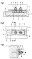
- the device for locking components (1) consists of two locking elements (2) which are rotatably guided in the area of a carrier (3).
- the carrier (3) is designed as an angle profile.
- the locking element (2) essentially consists of a bolt (4) which is connected in the region of its end facing away from the component (1) with a crossmember (5) which, in the region of its ends, the bolt (4) with projections (6, 7) overhanging.
- the projections (6, 7) engage behind upper boundary webs (8, 9) of seat rails (10) which are arranged in the area of an aircraft floor (11).
- the seat rails (10) are provided with receptacle extensions (12) and connecting grooves (13) which transfer the receptacle extensions (12) into one another.
- the essentially circularly contoured receiving extensions (11) Transversely to a longitudinal direction of the seat rail (10), the essentially circularly contoured receiving extensions (11) have a larger diameter than the connecting grooves (13).
- the bolt (4) is provided with an external thread (14) into which a nut (15) engages, which braces the bolt (4) relative to the carrier (3) after tightening.
- a notch (16) is provided in the area of an upper side of the bolt (4) into which a screwdriver can engage.
- positioning elements (17) are provided which extend essentially parallel to the bolt (4).
- the positioning elements (17) are at a distance from one another which corresponds to the distance between the receptacle extensions (12).
- the positioning elements (17) are provided with side recesses (18) into which the locking elements (2) engage with the projections (6, 7) in an unlocked state.
- the side recesses (18) have stop faces (19) for the defined positioning of the locking elements (2) in an unlocked state.
- only one locking element (2) is provided, which is arranged between two positioning elements (17).
- locking pins (20) are provided which penetrate the carrier (3).
- the locking elements (2) are rotated into their unlocking position and with the positioning elements (17) designed as xy-stops into the receptacle extensions (12) arranged, for example, in an inch grid. introduced.
- the locking elements (2) are then rotated such that the projections (6, 7) engage under the limiting webs (8, 9). In this way, locking in the z direction is also carried out.
- the positioning elements (17) have been inserted into the receptacle extensions (12), there is no longer any displacement, but only a locking of the locking elements (2).
Landscapes
- Engineering & Computer Science (AREA)
- Aviation & Aerospace Engineering (AREA)
- Seats For Vehicles (AREA)
- Connection Of Plates (AREA)
Claims (9)
- Dispositif destiné au verrouillage de pièces pour l'intérieur des avions, ledit dispositif fixant les pièces (1) dans des rails de fixation (10) montés dans le sol de l'avion (11) et présentant au moins un élément de verrouillage (2) introduit dans un support (3) de manière à pouvoir pivoter et pourvu d'au moins une saillie (6, 7), laquelle, en position verrouillée, s'engrène à l'arrière d'une arête supérieure de délimitation (8, 9) du rail de fixation (10), l'élément de verrouillage (2) étant conçu comme un boulon (4) relié au niveau de l'extrémité opposée à son support (3) avec une traverse (5) dépassant latéralement le boulon (4) afin de former deux saillies (6, 7), le boulon (4) présentant un filet extérieur (14) assurant son blocage par rapport au support (3), dispositif dans le cas duquel au moins un boulon (4) est disposé entre les deux éléments de positionnement (17) s'étendant principalement parallèlement au boulon (4) et pouvant être introduits dans des logements de réception (12) du rail de fixation (10), caractérisé en ce que les éléments de positionnement (17) sont pourvus d'évidements latéraux (18) tournés vers la traverse (5) et recevant les saillies (6, 7) dans une position déverrouillée.
- Dispositif selon la revendication 1, caractérisé en ce que au niveau de l'évidement latéral (18) est prévue une surface d'arrêt (19) destinée à limiter le mouvement de pivotement de la traverse (5).
- Dispositif selon l'une ou l'autre des revendications 1 et 2, caractérisé en ce que la traverse (5) présente transversalement à une direction longitudinale du rail de fixation (10) une largeur légèrement inférieure à la dimension d'une rainure de liaison (13) assurant la transition entre les extensions de réception (12).
- Dispositif selon l'une ou l'autre des revendications 1 à 3, caractérisé en ce que les chevilles d'arrêt (20) sont prévues pour la fixation des éléments de positionnement (17) par rapport aux pièces (1) s'étendant principalement parallèlement au boulon (4).
- Dispositif selon l'une ou l'autre des revendications 1 à 4, caractérisé en ce que trois éléments de verrouillage (2) sont disposés alternativement les uns derrière les autres dans la direction d'une extension longitudinale du rail de fixation (10).
- Dispositif selon l'une ou l'autre des revendications 1 à 5, caractérisé en ce que le support (3) est conçu comme un élément de soutien au sol de la pièce (1).
- Dispositif selon l'une ou l'autre des revendications 1 à 5, caractérisé en ce que le support (3) est conçu comme une plaque de base (21) s'étendant principalement parallèlement à une limitation inférieure de la pièce (1).
- Dispositif selon l'une ou l'autre des revendications 1 à 7, caractérisé en ce que le bouton (4) est pourvu au niveau de son extension opposée à la traverse (5) d'une entaille (16) destinée au déclenchement de mouvements de rotation respectivement à l'empêchement de mouvements de rotation.
- Dispositif selon l'une ou l'autre des revendications 1 à 8, caractérisé en ce que sur le filet extérieur (14) est monté un écrou (15) destiné à bloquer le boulon.
Applications Claiming Priority (2)
| Application Number | Priority Date | Filing Date | Title |
|---|---|---|---|
| DE4212694A DE4212694C2 (de) | 1992-04-16 | 1992-04-16 | Vorrichtung zur Verriegelung |
| DE4212694 | 1992-04-16 |
Publications (2)
| Publication Number | Publication Date |
|---|---|
| EP0565973A1 EP0565973A1 (fr) | 1993-10-20 |
| EP0565973B1 true EP0565973B1 (fr) | 1995-12-27 |
Family
ID=6456915
Family Applications (1)
| Application Number | Title | Priority Date | Filing Date |
|---|---|---|---|
| EP93105542A Expired - Lifetime EP0565973B1 (fr) | 1992-04-16 | 1993-04-03 | Dispositif d'ancrage |
Country Status (3)
| Country | Link |
|---|---|
| US (1) | US5302065A (fr) |
| EP (1) | EP0565973B1 (fr) |
| DE (2) | DE4212694C2 (fr) |
Families Citing this family (47)
| Publication number | Priority date | Publication date | Assignee | Title |
|---|---|---|---|---|
| DE19634791C1 (de) * | 1996-08-29 | 1997-12-04 | Daimler Benz Aerospace Airbus | X-Riegelelement für ein System zum Verriegeln von Luftfrachtladeeinheiten in einem Frachtladeraum eines Flugzeuges |
| GB2330614B (en) * | 1997-07-25 | 2001-10-03 | Baker Martin Aircraft Co | Fittings for securing seating and other equipment in aircraft |
| US5871318A (en) * | 1997-11-12 | 1999-02-16 | Be Aerospace, Inc. | Quick-release track fastener |
| US5823727A (en) * | 1998-04-02 | 1998-10-20 | Lee; Ray | Anchor fittings for securing objects on a elongated track |
| DE19961734C1 (de) | 1999-12-21 | 2001-03-01 | Eads Airbus Gmbh | Frachtladesystem für ein Flugzeug zum Be- und/oder Entladen von Beladungseinheiten |
| DE10034991C1 (de) * | 2000-07-19 | 2001-09-06 | Eads Airbus Gmbh | Werkzeug zur Betätigung einer auf einem Gewindeschaft eines pilzförmigen Befestigungselementes angeordneten Nutmutter zwecks mechanischer Befestigung bzw. Lösung eines Sitzbeines eines Fluggastsitzes auf einer Sitzschiene |
| DE10103840A1 (de) * | 2001-01-25 | 2002-08-01 | Junker & Partner Gmbh | Vorrichtung für die Verbindung zweier Bauteile |
| FR2835790B1 (fr) * | 2002-02-08 | 2004-05-07 | Antolin Grupo Ing Sa | Dispositif de calage vertical et automatique d'un siege de vehicule |
| US20040237749A1 (en) * | 2003-05-29 | 2004-12-02 | Green Kevin J. | Extractable fastener |
| US7137768B2 (en) * | 2003-10-10 | 2006-11-21 | Illinois Tool Works Inc | Fastener assembly |
| FR2864481B1 (fr) * | 2003-12-26 | 2006-04-07 | Renault Sas | Agencement pour le montage d'un siege sur le plancher d'un vehicule au moyen de plots de guidage escamotables |
| US7021596B2 (en) * | 2004-02-11 | 2006-04-04 | Goodrich Corporation | Aircraft seat floor track quick release fitting |
| US6918722B1 (en) | 2004-02-27 | 2005-07-19 | Valeda Company Llc | Double plunger track fitting |
| US7637705B2 (en) * | 2004-02-27 | 2009-12-29 | Valeda Company | Track fitting with visual indicia of engagement |
| US7229238B2 (en) * | 2004-03-25 | 2007-06-12 | Valeda Company Llc | Wheelchair docking system |
| US7427049B2 (en) * | 2006-07-24 | 2008-09-23 | Ami Industries, Inc. | Aircraft seat floor track fitting |
| DE102006061455A1 (de) * | 2006-12-23 | 2008-06-26 | DRäGER AEROSPACE GMBH | Anordnung zumindest einer Personal Service Unit in einem Fahrzeug |
| DE102012012686B4 (de) * | 2012-06-27 | 2014-12-11 | Airbus Defence and Space GmbH | Luftfahrzeug mit einer Anzahl Reihen von in Fahrzeuglängsrichtung hinter einander angeordneter Sitzanordnungen mit längsverschiebbaren Sitzreihen, Sitzanordnung und deren Verwendung |
| US9618118B2 (en) * | 2013-05-23 | 2017-04-11 | Alaska Airlines, Inc. | Air seal assembly for aircraft flap seal |
| EP3009350A1 (fr) * | 2014-10-17 | 2016-04-20 | Airbus Defence and Space GmbH | Système de fixation de siège, siège ou groupe de sièges, cabine d'aéronef et procédé de fixation d'un siège ou d'un groupe de sièges |
| DE102017131057A1 (de) | 2017-12-22 | 2019-06-27 | Airbus Operations Gmbh | Sitzgruppe für ein Passagierflugzeug |
| DE102018101836B4 (de) * | 2018-01-26 | 2023-05-04 | Airbus Operations Gmbh | Befestigungssystem zum Befestigen von Einbauten in einem Fahrzeug |
| US10900607B1 (en) | 2018-03-14 | 2021-01-26 | Luther CIFERS | Accessory mounting track with one or more discrete locking positions |
| US11040639B2 (en) | 2018-05-04 | 2021-06-22 | Lear Corporation | Track assembly |
| US10759308B2 (en) | 2018-05-04 | 2020-09-01 | Lear Corporation | Support assembly |
| US10882420B2 (en) | 2019-03-08 | 2021-01-05 | Lear Corporation | Track assembly |
| US11358497B2 (en) | 2018-05-04 | 2022-06-14 | Lear Corporation | Track system having a rolling member |
| US10906431B2 (en) | 2018-05-04 | 2021-02-02 | Lear Corporation | Track assembly |
| US11040638B2 (en) | 2018-05-04 | 2021-06-22 | Lear Corporation | Track assembly |
| US10926667B2 (en) | 2018-05-04 | 2021-02-23 | Lear Corporation | Track assembly |
| CN109334994B (zh) * | 2018-11-19 | 2023-09-01 | 山东太古飞机工程有限公司 | 一种用于飞机座椅滑轨的锁止机构 |
| US11225201B2 (en) | 2018-12-10 | 2022-01-18 | Lear Corporation | Track assembly |
| US11440482B2 (en) | 2018-12-10 | 2022-09-13 | Lear Corporation | Track assembly |
| US11117538B2 (en) | 2018-12-17 | 2021-09-14 | Lear Corporation | Electrical assembly |
| US10855037B2 (en) | 2018-12-17 | 2020-12-01 | Lear Corporation | Support assembly with a support member and a track assembly |
| US10950977B2 (en) | 2018-12-18 | 2021-03-16 | Lear Corporation | Track assembly for a vehicle component |
| EP4253225A3 (fr) * | 2018-12-31 | 2023-11-29 | Airbus Operations GmbH | Dispositifs, systèmes et procédés associés de chargement de soute et procédés associés |
| US11975665B2 (en) | 2019-02-20 | 2024-05-07 | Lear Corporation | Electrical assembly |
| US11040653B2 (en) | 2019-02-25 | 2021-06-22 | Lear Corporation | Track assembly |
| US11299075B2 (en) | 2019-03-06 | 2022-04-12 | Lear Corporation | Electrical assembly |
| US11807142B2 (en) | 2019-03-06 | 2023-11-07 | Lear Corporation | Electrical track assembly |
| US11323114B2 (en) | 2019-10-04 | 2022-05-03 | Lear Corporation | Electrical system |
| US11634101B2 (en) | 2019-10-04 | 2023-04-25 | Lear Corporation | Removable component system |
| US11463083B2 (en) | 2019-10-04 | 2022-10-04 | Lear Corporation | Electrical system |
| US20210261022A1 (en) | 2020-02-21 | 2021-08-26 | Lear Corporation | Track system with a support member |
| US11505141B2 (en) | 2020-10-23 | 2022-11-22 | Lear Corporation | Electrical system with track assembly and support assembly |
| CN113955074B (zh) * | 2021-12-03 | 2023-07-21 | 陕西飞机工业有限责任公司 | 一种用于安装舱内设备的快卸锁 |
Family Cites Families (14)
| Publication number | Priority date | Publication date | Assignee | Title |
|---|---|---|---|---|
| US1933536A (en) * | 1930-05-16 | 1933-11-07 | Floor Accessories Company Inc | Concrete insert |
| US1985333A (en) * | 1931-12-11 | 1934-12-25 | William R Wiley | Bolt |
| US2163446A (en) * | 1937-08-17 | 1939-06-20 | Richard P Heckman | Insert anchor |
| US2859057A (en) * | 1956-08-20 | 1958-11-04 | Aeroquip Corp | Rail |
| US3212457A (en) * | 1961-07-18 | 1965-10-19 | Brown Line Corp | Anchor means |
| US3241501A (en) * | 1964-01-08 | 1966-03-22 | Aid Corp | Hold-down device |
| US3306234A (en) * | 1964-05-14 | 1967-02-28 | Boeing Co | Securing device |
| US3810534A (en) * | 1970-04-22 | 1974-05-14 | Ancra Corp | Automatic pallet locking device |
| DE2556000C2 (de) * | 1975-12-12 | 1983-02-03 | Vereinigte Flugtechnische Werke Gmbh, 2800 Bremen | Unverlierbares Befestigungselement für Sitzschienen |
| DE2649149B2 (de) * | 1976-10-28 | 1981-05-14 | Gardinia Vorhangschienenfabrik Klein & Wälder, 7972 Isny | Endfeststeller zum lösbaren Einrasten von Vorhanggleitern |
| US4230432A (en) * | 1979-02-27 | 1980-10-28 | Fairchild Industries, Inc. | Track fastener |
| US4449875A (en) * | 1982-07-22 | 1984-05-22 | Uop Inc. | Seat back mounting system |
| US4784554A (en) * | 1985-09-26 | 1988-11-15 | Break Douglas G | T-bolt assembly |
| EP0431786A1 (fr) * | 1989-12-04 | 1991-06-12 | Camloc (U.K.) Limited | Fixateur structurel à démontage rapide |
-
1992
- 1992-04-16 DE DE4212694A patent/DE4212694C2/de not_active Expired - Lifetime
-
1993
- 1993-04-03 EP EP93105542A patent/EP0565973B1/fr not_active Expired - Lifetime
- 1993-04-03 DE DE59301231T patent/DE59301231D1/de not_active Expired - Lifetime
- 1993-04-16 US US08/048,826 patent/US5302065A/en not_active Expired - Lifetime
Also Published As
| Publication number | Publication date |
|---|---|
| DE59301231D1 (de) | 1996-02-08 |
| DE4212694A1 (de) | 1993-10-21 |
| US5302065A (en) | 1994-04-12 |
| DE4212694C2 (de) | 1995-09-21 |
| EP0565973A1 (fr) | 1993-10-20 |
Similar Documents
| Publication | Publication Date | Title |
|---|---|---|
| EP0565973B1 (fr) | Dispositif d'ancrage | |
| DE3726711C2 (fr) | ||
| EP0583295A1 (fr) | Dispositif de fixation rapide. | |
| WO1999002366A1 (fr) | Dispositif de fixation permettant une liberation rapide, un deplacement et un blocage rapide pour partie d'equipement de vehicule | |
| WO2007131791A1 (fr) | Dispositif de fixation d'un objet | |
| EP1442942A1 (fr) | Raccord à brides entre un longeron de véhicule et un élément de support fixable à ce dernier | |
| DE19538988A1 (de) | Tischüberbrückungsvorrichtung | |
| DE4241008C2 (de) | Vorrichtung zum lösbaren Befestigen eines Fahrradträgers am Heck eines Personenkraftwagens | |
| WO1999055554A1 (fr) | Dispositif de support reglable pour ordinateur de bord monte dans un vehicule automobile, en particulier pour ordinateur portatif ou bloc-notes | |
| DE2659311A1 (de) | Laengsverschiebbarer und in waehlbaren laengslagen feststellbarer, insbesondere in kraftfahrzeugen anzuordnender sitz | |
| DE10124618B4 (de) | Rastbeschlag für einen Fahrzeugsitz | |
| DE4404392A1 (de) | Drehverriegelung zum lösbaren Verbinden von Eckbeschlägen aufeinanderstehender Container | |
| EP1291239B2 (fr) | Dispositif pour la fixation de la charge | |
| DE3831807A1 (de) | Niederhaltevorrichtung | |
| EP0496975B1 (fr) | Elément de raccordement | |
| EP4144597A1 (fr) | Structure de siège de véhicule et procédé de montage d'une structure de siège de véhicule | |
| DE3447178A1 (de) | Fluggastsitz | |
| DE69814570T2 (de) | Anordnung für einen ausnehmbaren und in Längsrichtung verstellbaren Sitz im Innenraum eines Kraftfahrzeuges | |
| DE102016111983B4 (de) | Modulares Schienensystem | |
| DE60214242T2 (de) | Struktur für das Halten eines Karosserieteiles | |
| EP0323623B1 (fr) | Méthode de verrouillage d'au moins deux couches de conteneurs ISO, chacune en nombre impair, pour former une unité de transport ainsi qu'une telle unité de transport | |
| DE3927736C2 (fr) | ||
| DE69919570T2 (de) | Befestigungsvorrichtung eines abnehmbaren sitzes an einem kraftfahrzeugboden | |
| DE19615144C2 (de) | Verbindung eines Sockels eines Kabelverteilerschrankes mit dessen Aufbau | |
| EP1036944A2 (fr) | Dispositif de fixation ainsi que boíte de connexion équipée d'un tel dispositif |
Legal Events
| Date | Code | Title | Description |
|---|---|---|---|
| PUAI | Public reference made under article 153(3) epc to a published international application that has entered the european phase |
Free format text: ORIGINAL CODE: 0009012 |
|
| AK | Designated contracting states |
Kind code of ref document: A1 Designated state(s): DE FR GB IT NL |
|
| 17P | Request for examination filed |
Effective date: 19940203 |
|
| 17Q | First examination report despatched |
Effective date: 19941219 |
|
| RAP1 | Party data changed (applicant data changed or rights of an application transferred) |
Owner name: DAIMLER-BENZ AEROSPACE AIRBUS GESELLSCHAFT MIT BES |
|
| GRAA | (expected) grant |
Free format text: ORIGINAL CODE: 0009210 |
|
| AK | Designated contracting states |
Kind code of ref document: B1 Designated state(s): DE FR GB IT NL |
|
| REF | Corresponds to: |
Ref document number: 59301231 Country of ref document: DE Date of ref document: 19960208 |
|
| ITF | It: translation for a ep patent filed |
Owner name: INVENTION S.N.C. |
|
| GBT | Gb: translation of ep patent filed (gb section 77(6)(a)/1977) |
Effective date: 19960217 |
|
| ET | Fr: translation filed | ||
| PLBE | No opposition filed within time limit |
Free format text: ORIGINAL CODE: 0009261 |
|
| STAA | Information on the status of an ep patent application or granted ep patent |
Free format text: STATUS: NO OPPOSITION FILED WITHIN TIME LIMIT |
|
| 26N | No opposition filed | ||
| REG | Reference to a national code |
Ref country code: FR Ref legal event code: CD |
|
| REG | Reference to a national code |
Ref country code: GB Ref legal event code: IF02 |
|
| PGFP | Annual fee paid to national office [announced via postgrant information from national office to epo] |
Ref country code: FR Payment date: 20110510 Year of fee payment: 19 Ref country code: DE Payment date: 20110421 Year of fee payment: 19 |
|
| PGFP | Annual fee paid to national office [announced via postgrant information from national office to epo] |
Ref country code: NL Payment date: 20110426 Year of fee payment: 19 Ref country code: GB Payment date: 20110421 Year of fee payment: 19 |
|
| PGFP | Annual fee paid to national office [announced via postgrant information from national office to epo] |
Ref country code: IT Payment date: 20110422 Year of fee payment: 19 |
|
| REG | Reference to a national code |
Ref country code: NL Ref legal event code: V1 Effective date: 20121101 |
|
| GBPC | Gb: european patent ceased through non-payment of renewal fee |
Effective date: 20120403 |
|
| REG | Reference to a national code |
Ref country code: FR Ref legal event code: ST Effective date: 20121228 |
|
| PG25 | Lapsed in a contracting state [announced via postgrant information from national office to epo] |
Ref country code: GB Free format text: LAPSE BECAUSE OF NON-PAYMENT OF DUE FEES Effective date: 20120403 |
|
| REG | Reference to a national code |
Ref country code: DE Ref legal event code: R119 Ref document number: 59301231 Country of ref document: DE Effective date: 20121101 |
|
| PG25 | Lapsed in a contracting state [announced via postgrant information from national office to epo] |
Ref country code: FR Free format text: LAPSE BECAUSE OF NON-PAYMENT OF DUE FEES Effective date: 20120430 Ref country code: IT Free format text: LAPSE BECAUSE OF NON-PAYMENT OF DUE FEES Effective date: 20120403 |
|
| PG25 | Lapsed in a contracting state [announced via postgrant information from national office to epo] |
Ref country code: NL Free format text: LAPSE BECAUSE OF NON-PAYMENT OF DUE FEES Effective date: 20121101 |
|
| PG25 | Lapsed in a contracting state [announced via postgrant information from national office to epo] |
Ref country code: DE Free format text: LAPSE BECAUSE OF NON-PAYMENT OF DUE FEES Effective date: 20121101 |