EP0562918B1 - Elément d'habillage d'une paroi et son utilisation pour porte d'ascenseur - Google Patents
Elément d'habillage d'une paroi et son utilisation pour porte d'ascenseur Download PDFInfo
- Publication number
- EP0562918B1 EP0562918B1 EP93400692A EP93400692A EP0562918B1 EP 0562918 B1 EP0562918 B1 EP 0562918B1 EP 93400692 A EP93400692 A EP 93400692A EP 93400692 A EP93400692 A EP 93400692A EP 0562918 B1 EP0562918 B1 EP 0562918B1
- Authority
- EP
- European Patent Office
- Prior art keywords
- clip
- rigid wall
- housing
- rigid
- wall
- Prior art date
- Legal status (The legal status is an assumption and is not a legal conclusion. Google has not performed a legal analysis and makes no representation as to the accuracy of the status listed.)
- Expired - Lifetime
Links
Images


Classifications
-
- B—PERFORMING OPERATIONS; TRANSPORTING
- B66—HOISTING; LIFTING; HAULING
- B66B—ELEVATORS; ESCALATORS OR MOVING WALKWAYS
- B66B13/00—Doors, gates, or other apparatus controlling access to, or exit from, cages or lift well landings
- B66B13/30—Constructional features of doors or gates
- B66B13/303—Details of door panels
-
- E—FIXED CONSTRUCTIONS
- E06—DOORS, WINDOWS, SHUTTERS, OR ROLLER BLINDS IN GENERAL; LADDERS
- E06B—FIXED OR MOVABLE CLOSURES FOR OPENINGS IN BUILDINGS, VEHICLES, FENCES OR LIKE ENCLOSURES IN GENERAL, e.g. DOORS, WINDOWS, BLINDS, GATES
- E06B1/00—Border constructions of openings in walls, floors, or ceilings; Frames to be rigidly mounted in such openings
- E06B1/04—Frames for doors, windows, or the like to be fixed in openings
- E06B1/34—Coverings, e.g. protecting against weather, for decorative purposes
-
- F—MECHANICAL ENGINEERING; LIGHTING; HEATING; WEAPONS; BLASTING
- F16—ENGINEERING ELEMENTS AND UNITS; GENERAL MEASURES FOR PRODUCING AND MAINTAINING EFFECTIVE FUNCTIONING OF MACHINES OR INSTALLATIONS; THERMAL INSULATION IN GENERAL
- F16B—DEVICES FOR FASTENING OR SECURING CONSTRUCTIONAL ELEMENTS OR MACHINE PARTS TOGETHER, e.g. NAILS, BOLTS, CIRCLIPS, CLAMPS, CLIPS OR WEDGES; JOINTS OR JOINTING
- F16B2/00—Friction-grip releasable fastenings
- F16B2/20—Clips, i.e. with gripping action effected solely by the inherent resistance to deformation of the material of the fastening
- F16B2/22—Clips, i.e. with gripping action effected solely by the inherent resistance to deformation of the material of the fastening of resilient material, e.g. rubbery material
- F16B2/24—Clips, i.e. with gripping action effected solely by the inherent resistance to deformation of the material of the fastening of resilient material, e.g. rubbery material of metal
- F16B2/248—Clips, i.e. with gripping action effected solely by the inherent resistance to deformation of the material of the fastening of resilient material, e.g. rubbery material of metal of wire
Definitions
- the present invention relates to a covering element for a rigid wall such as a wall, a partition or a door or window jamb (US-A-1541055).
- the object of the invention is to provide a means of improving the everyday living environment by changing the external appearance of a wall using covering elements of a particular design.
- the invention also relates to a protective covering element for a rigid wall.
- the covering element according to the invention makes it possible to cover at least partially an outer side of a rigid wall.
- This element comprises a hollow rigid profile provided with at least one longitudinal housing in the hollow with a narrowed longitudinal opening, at least two elastic clips whose arms slide longitudinally with the interior surface of the housing and whose heads project outside the narrowed opening of the housing, each clip head having a length greater than the thickness of the wall rigid and being able to pass through a hole made in the rigid wall, and at least two fixing corners cooperating in a removable manner, on the inside of the rigid wall, with the clip heads having passed through the rigid wall.
- the rigid profile has a constant section is made of a metallic material or a rigid plastic material.
- the clips can be produced by bending a metal wire with the head of the clip making a loop in a plane transverse to the branches of clips which extend longitudinally inside the housing.
- the fixing of the covering element on the outer side of the rigid wall is obtained in this case by the forced insertion of the corners in the loops of clip heads protruding from the inner side of the rigid wall after passing through the corresponding holes, widening the loop by introduction of the corner and / or the corner itself preventing the extraction movement of the clip heads towards the outside of the rigid wall.
- the profile comprises two parallel longitudinal housings in the hollow, in each housing having two elastic clips
- a clip in a housing is associated in pairs with a clip of the second housing so as to pass through two corresponding holes in the rigid wall located in a plane transverse to the profile
- a fixing corner in the form of an inverted U is produced for each pair of clips, the branches of inverted U cooperating with the two projecting heads of clips on the inside of the rigid wall.
- a particularly interesting application of the present invention is to equip the uprights of an elevator door with the trim elements of the invention in order to change the austere appearance of conventional elevator doors.
- the main concerns of elevator manufacturers have so far been conditioned by building construction constraints and standards
- the exterior appearance of elevator doors is left in the background, which can deteriorate the aesthetic harmony and styles of the frame in which the elevator doors are integrated
- the use of the specific trim elements according to the invention overcomes these drawbacks by making the living environment more harmonious.
- the covering element comprises a rigid profile 1 with constant section, elastic clips 2 and fixing corners 3.
- the profile 1 has a hollow profile and longitudinal housings 4 located in the hollow with each a narrowed longitudinal opening 5.
- the housings 4 are parallel to each other and each receives at least two elastic clips 2.
- Each clip 2 is produced by bending a metal wire which forms two branches 6 s' extending longitudinally which are joined by a loop 7 extending transversely and forming a clip head.
- the clips 2 are introduced longitudinally inside a housing 4, as indicated by the arrow 8, with the arms 6 sliding longitudinally relative to the interior surface of the housing 4 and with the head 7 projecting outside of the narrowed opening 5 of the housing 4.
- the branches 6 of the clips 2 can slide inside the housings 4 so as to be able to adjust the positioning of the clip head 7 which projects outside the opening 5 of the housing .
- the clips 2 are made to slide longitudinally in the housings 4 by means of the heads 7 of the projecting clip so as to bring them opposite the holes 10 made in the rigid wall 9.
- the heads 7 of the clip are then introduced through the holes 10 until the openings 5 bear against the outside of the wall 9.
- the clip heads 7 have a length greater than the thickness of the wall 9 so that after having passed through the wall 9 they present a loop in the plane transverse from the inside of the wall 9.
- the corner 3 produced in the form of an inverted U is then used to fix the heads 7 of the clips 2.
- the branches of the inverted U 3 are introduced into each of the loops of the pair of clip heads 7 which protrude on the inside of the wall 9.
- FIG. 5 shows a conventional automatic elevator door which comprises two vertical and flat front uprights 11, connected to each other by a horizontal front upright 12, the uprights 11, 12 forming an external frame for the automatic door proper 13.
- the door is embedded in a wall 14.
- On one of the vertical uprights 11 is installed a control button 15 of the elevator.
- FIG. 6 is mounted an automatic elevator door of the conventional type of FIG. 5 equipped with a clothing element on each of the vertical facade uprights 11.
- the section 1 of the clothing element is mounted on the vertical façade upright 11 with the fixing means 2, 3 passing through the wall of the façade upright 11 (see FIGS. 2, 3 and 4).
- the control button 15 is embedded in an opening made in one of the sections 1 of clothing elements.
- Each profile 1 can include days 16 allowing the lighting of the door thanks to lighting lamps arranged in the space formed between the hollow of the profile 1 and the outside side of the vertical upright of facade 11.
- the appearance of the elevator doors can be adapted to better integrate them into the surrounding living environment.
Landscapes
- Engineering & Computer Science (AREA)
- General Engineering & Computer Science (AREA)
- Mechanical Engineering (AREA)
- Civil Engineering (AREA)
- Structural Engineering (AREA)
- Elevator Door Apparatuses (AREA)
Description
- La présente invention concerne un élément d'habillage d'une paroi rigide telle qu'un mur, une cloison ou un montant de porte ou de fenêtre (US-A-1541055).
- Le but de l'invention est de fournir un moyen d'amélioration du cadre de vie quotidienne en changeant l'aspect extérieur d'une paroi à l'aide d'éléments d'habillage d'une conception particulière.
- L'invention a également pour objet un élément d'habillage de protection d'une paroi rigide.
- L'élément d'habillage selon l'invention permet de couvrir au moins partiellement un côté extérieur d'une paroi rigide Cet élément comprend un profilé rigide creux pourvu d'au moins un logement longitudinal dans le creux avec une ouverture longitudinale rétrécie, au moins deux clips élastiques dont les branches coopèrent de façon coulissante longitudinalement avec la surface intérieure du logement et dont les têtes font saillie à l'extérieur de l'ouverture rétrécie du logement, chaque tête de clip ayant une longueur supérieure à l'épaisseur de la paroi rigide et pouvant traverser un trou pratiqué dans la paroi rigide, et au moins deux coins de fixation coopérant de façon amovible, du côté intérieur de la paroi rigide, avec les têtes de clip ayant traversé la paroi rigide.
- Le profilé rigide présente une section constante est réalisé en un matériau métallique ou en une matière plastique rigide. Les clips peuvent être réalisés par pliage d'un fil métallique avec la tête du clip faisant une boucle dans un plan transversal aux branches de clips qui s'étendent longitudinalement à l'intérieur du logement La fixation de l'élément d'habillage sur le côté extérieur de la paroi rigide est obtenue dans ce cas par l'introduction à force des coins dans les boucles de têtes de clips dépassant le côté intérieur de la paroi rigide après avoir traversé les trous correspondants, l'élargissement de la boucle par l'introduction du coin ou/et le coin lui-même empêchant le mouvement d'extraction des têtes de clips vers le côté extérieur de la paroi rigide.
- Selon un mode particulier de réalisation de l'invention, le profilé comprend deux logements longitudinaux parallèles dans le creux, dans chaque logement se trouvant deux clips élastiques Un clip dans un logement est associé par paire à un clip du second logement de façon à traverser deux trous correspondants de la paroi rigide situés dans un plan transversal au profilé De préférence dans ce cas, on réalise un coin de fixation en forme de U inversé pour chaque paire de clips, les branches de U inversé coopérant avec les deux têtes de clips faisant saillie du côté intérieur de la paroi rigide.
- Une application particulièrement intéressante de la présente invention est d'équiper les montants de façade d'une porte d'ascenseur à l'aide des éléments d'habillage de l'invention afin de changer l'aspect austère des portes d'ascenseur classiques En effet, les soucis principaux des constructeurs d'ascenseurs sont jusqu'à présent conditionnés par des contraintes et normes de construction du bâtiment L'aspect extérieur des portes d'ascenseur est laissé en second plan, ce qui peut détériorer l'harmonie esthétique et des styles du cadre dans lequel les portes d'ascenseur sont intégrées L'utilisation des éléments d'habillage particuliers selon l'invention permet de pallier ces inconvénients en rendant le cadre de vie plus harmonieux.
- L'invention sera mieux comprise à l'étude de la description détaillée d'un mode de réalisation particulier pris à titre nullement limitatif et illustré par des dessins annexés, sur lesquels :
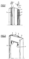
- la figure 1 est une vue partielle en perspective du profilé de l'élément d'habillage avec les clips élastiques,
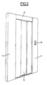
- la figure 2 est une vue schématique de l'élément d'habillage fixé sur une paroi ,
- la figure 3 est une vue de détail en coupe longitudinale pour montrer le mécanisme de fixation de l'élément d'habillage,
- la figure 4 est une vue partielle en coupe transversale montrant le même système de fixation,
- la figure 5 est une vue extérieure d'une porte d'ascenseur classique,
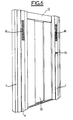
- la figure 6 est une vue extérieure de la porte d'ascenseur de la figure 5 équipée des éléments d'habillage sur les montants de façade.
- la figure 7 est une vue schématique en coupe transversale de la porte d'ascenseur de la figure 6 en position fermée, et
- la figure 8 est une vue schématique en coupe transversale de la porte d'ascenseur de la figure 6 en position ouverte.
- Comme illustré sur les figures 1 et 2, l'élément d'habillage comprend un profilé rigide 1 à section constante, des clips élastiques 2 et des coins de fixation 3. Le profilé 1 présente un profil creux et des logements longitudinaux 4 situés dans le creux avec chacun une ouverture longitudinale rétrécie 5. Les logements 4 sont parallèles l'un à l'autre et chacun reçoit au moins deux clips élastiques 2. Chaque clip 2 est réalisé par pliage d'un fil métallique qui forme deux branches 6 s'étendant longitudinalement qui sont réunies par une boucle 7 s'étendant transversalement et formant tête de clip.
- Les clips 2 sont introduits longitudinalement à l'intérieur d'un logement 4, comme indiqué par la flèche 8, avec les branches 6 coulissant longitudinalement par rapport à la surface intérieure du logement 4 et avec la tête 7 faisant saillie à l'extérieur de l'ouverture rétrécie 5 du logement 4. Les branches 6 des clips 2 peuvent coulisser à l'intérieur des logements 4 afin de pouvoir ajuster le positionnement de la tête 7 de clip qui fait saillie à l'extérieur de l'ouverture 5 de logement.
- Comme montré sur les figures 2, 3 et 4, on peut associer par paire les clips 2 se trouvant dans les deux logements longitudinaux 4 en les plaçant dans un même plan transversal, cela en vue de monter le profilé 1 sur le côté extérieur d'une paroi rigide 9. La paroi 9 présente des trous 10 par paire situés sur un plan transversal et ayant un écartement transversal identique à celui des ouvertures longitudinales 5 des logements 4 correspondants. Lors du montage, on fait coulisser longitudinalement les clips 2 dans les logements 4 au moyen des têtes 7 en saillie de clip pour les ramener en regard des trous 10 pratiqués dans la paroi rigide 9. On introduit ensuite les têtes 7 de clip au travers des trous 10 jusqu'à ce que les ouvertures 5 soient en appui contre le côté extérieur de la paroi 9. Les têtes 7 de clip ont une longueur supérieure à l'épaisseur de la paroi 9 de façon à ce que après avoir traversé la paroi 9 elles présentent une boucle dans le plan transversal du côté intérieur de la paroi 9.
- Le coin 3 réalisé sous forme d'un U inversé est ensuite utilisé pour fixer les têtes 7 des clips 2. Pour ce faire, on introduit les branches du U inversé 3 dans chacune des boucles de la paire de têtes 7 de clip qui font saillie du côté intérieur de la paroi 9.
- Pour le démontage du profilé 1, il suffit d'enlever le coin 3 de fixation et de retirer le profilé 1 transversalement de la paroi 9 en dégageant les têtes 7 de clip des trous 10 de la paroi 9. On peut ainsi changer l'aspect de l'habillage de la paroi 9 en changeant la forme, la matière ou la couleur du profilé 1.
- Sur les figures 5, 6, 7 et 8 est illustrée une application particulière de l'élément d'habillage pour une porte d'ascenseur.
- La figure 5 montre une porte d'ascenseur automatique classique qui comprend deux montants de façade 11 verticaux et plans, reliés entre eux par un montant horizontal de façade 12, les montants 11, 12 formant un cadre extérieur pour la porte automatique proprement dite 13. La porte est encastrée dans un mur 14. Sur un des montants verticaux 11 est installé un bouton de commande 15 de l'ascenseur.
- Sur la figure 6 est montée une porte d'ascenseur automatique du type classique de la figure 5 équipée d'un élément d'habillement sur chacun des montants verticaux de façade 11. Le profilé 1 de l'élément d'habillement est monté sur le montant vertical de façade 11 avec les moyens de fixation 2, 3 traversant la paroi du montant de façade 11 (voir figures 2, 3 et 4). Le bouton de commande 15 est encastré dans une ouverture pratiquée dans un des profilés 1 d'éléments d'habillement. Chaque profilé 1 peut comporter des jours 16 permettant l'éclairage de la porte grâce à des lampes d'éclairage disposées dans l'espace formé entre le creux du profilé 1 et le côté extérieur du montant vertical de façade 11.
- Grâce à l'invention, on peut adapter l'aspect des portes d'ascenseur pour mieux les intégrer dans le cadre de vie environnant.
Claims (6)
- Elément d'habillage du côté extérieur d'une paroi rigide (9), caractérisé par le fait qu'il comprend un profilé rigide creux (2) pourvu d'au moins un logement longitudinal (4) dans le creux avec une ouverture longitudinale rétrécie (5), au moins deux clips élastiques (2) dont les branches (6) coopèrent de façon coulissante longitudinalement avec la surface interne du logement et dont les têtes (7) font saillie à l'extérieur de l'ouverture rétrécie du logement, chaque tête de clip ayant une longueur supérieure à l'épaisseur de la paroi rigide et pouvant traverser un trou (10) pratiqué dans la paroi rigide, et au moins deux coins de fixation (3) coopérant de façon amovible, du côté intérieur de la paroi rigide, avec les têtes de clip ayant traversé la paroi rigide.
- Elément d'habillage selon la revendication 1, caractérisé par le fait que chaque clip (2) est obtenu par pliage d'un fil métallique avec les branches (6) s'étendant longitudinalement et la tête (7) formant une boucle dans le plan transversal, et que le coin (3) est introduit dans la boucle de la tête de clip dépassant le côté intérieur de la paroi rigide (9) empêchant ainsi le mouvement d'extraction de la tête (7) de clip du trou (10) de la paroi.
- Elément d'habillage selon la revendication 2, caractérisé par le fait que le profilé comprend deux logements longitudinaux (4) parallèles dans le creux, que chaque clip se trouvant dans un logement est associé par paire à un clip se trouvant dans l'autre logement dans un plan transversal au profilé pour coopérer avec deux trous (10) correspondants de la paroi rigide (9), et que à chaque paire de clips (2) est associé un coin de fixation (3) en forme de U inversé dont les branches coopèrent avec les têtes (7) respectives des clips.
- Elément d'habillage selon l'une des revendications précédentes, caractérisé par le fait que le profilé (1) est réalisé en matériau métallique ou en matière plastique rigide.
- Elément d'habillage selon l'une des revendications précédentes, caractérisé par le fait que le profilé (1) est partiellement ajouré.
- Utilisation d'au moins un élément d'habillage selon l'une des revendications précédentes pour une porte d'ascenseur.
Applications Claiming Priority (2)
| Application Number | Priority Date | Filing Date | Title |
|---|---|---|---|
| FR9203742A FR2689159A1 (fr) | 1992-03-27 | 1992-03-27 | Elément d'habillage d'une paroi et son utilisation pour porte d'ascenseur. |
| FR9203742 | 1992-03-27 |
Publications (2)
| Publication Number | Publication Date |
|---|---|
| EP0562918A1 EP0562918A1 (fr) | 1993-09-29 |
| EP0562918B1 true EP0562918B1 (fr) | 1996-11-27 |
Family
ID=9428175
Family Applications (1)
| Application Number | Title | Priority Date | Filing Date |
|---|---|---|---|
| EP93400692A Expired - Lifetime EP0562918B1 (fr) | 1992-03-27 | 1993-03-18 | Elément d'habillage d'une paroi et son utilisation pour porte d'ascenseur |
Country Status (5)
| Country | Link |
|---|---|
| EP (1) | EP0562918B1 (fr) |
| AT (1) | ATE145706T1 (fr) |
| DE (1) | DE69306147D1 (fr) |
| ES (1) | ES2097465T3 (fr) |
| FR (1) | FR2689159A1 (fr) |
Family Cites Families (8)
| Publication number | Priority date | Publication date | Assignee | Title |
|---|---|---|---|---|
| BE667549A (fr) * | ||||
| US1327441A (en) * | 1916-07-07 | 1920-01-06 | Mesker Brothers Iron Company | Metallic window construction |
| US1541055A (en) * | 1924-09-20 | 1925-06-09 | Katz Martin | Mounting for store windows |
| US1950822A (en) * | 1930-12-12 | 1934-03-13 | Carl W Siegwarth | Window installation |
| US2787911A (en) * | 1956-05-24 | 1957-04-09 | Russel H Kirkhof | Snap mechanical movement |
| US3373463A (en) * | 1966-04-25 | 1968-03-19 | Chrysler Corp | Molding clip |
| US4064667A (en) * | 1976-08-06 | 1977-12-27 | Montgomery Elevator Company | Decorative jamb structure for elevator entranceways |
| DE3117046A1 (de) * | 1981-04-29 | 1982-11-18 | Götz Metallbau GmbH, 8360 Deggendorf | Abdeckvorrichtung fuer austauschfenster |
-
1992
- 1992-03-27 FR FR9203742A patent/FR2689159A1/fr not_active Withdrawn
-
1993
- 1993-03-18 ES ES93400692T patent/ES2097465T3/es not_active Expired - Lifetime
- 1993-03-18 EP EP93400692A patent/EP0562918B1/fr not_active Expired - Lifetime
- 1993-03-18 AT AT93400692T patent/ATE145706T1/de not_active IP Right Cessation
- 1993-03-18 DE DE69306147T patent/DE69306147D1/de not_active Expired - Lifetime
Also Published As
| Publication number | Publication date |
|---|---|
| DE69306147D1 (de) | 1997-01-09 |
| EP0562918A1 (fr) | 1993-09-29 |
| FR2689159A1 (fr) | 1993-10-01 |
| ATE145706T1 (de) | 1996-12-15 |
| ES2097465T3 (es) | 1997-04-01 |
Similar Documents
| Publication | Publication Date | Title |
|---|---|---|
| EP0076174B2 (fr) | Pare-soleil, notamment pour véhicule automobile | |
| FR2633490A1 (fr) | Porte pour animaux familiers | |
| FR2635248A1 (fr) | Boitier destine a recevoir des elements electriques et electroniques | |
| BE512172A (fr) | ||
| EP1035297A1 (fr) | Coffre de volet roulant, joue et profile de recouvrement pour ce coffre | |
| FR3100831A1 (fr) | procédé de fabrication d’un panneau notamment pour construction légère et panneau et construction légère | |
| EP0562918A1 (fr) | Elément d'habillage d'une paroi et son utilisation pour porte d'ascenseur | |
| FR2799497A1 (fr) | Coffre pour volets roulants ou equivalents | |
| EP3205787B1 (fr) | Lisse pour la réalisation d'une fausse paroi à toile tendue formée de deux profilés assemblés de manière amovible et fausse paroi comprenant une telle lisse | |
| BE1011029A3 (fr) | Profile pour caisson de volet. | |
| FR2517722A1 (fr) | Dispositif de fixation des panneaux de revetement de plafonds | |
| FR3048014A1 (fr) | Porte souple, a enroulement, pour une baie de batiment | |
| EP1302601A1 (fr) | Dispositif de cloison intérieure à joint creux | |
| FR3062864A1 (fr) | Procede de montage d'un revetement souple tendu sur un cadre de fixation et cadre de fixation pour la mise en oeuvre dudit procede | |
| EP4455429B1 (fr) | Panneau brise-vue ou d'occultation de clôtures en treillis rigide et son procédé de fixation | |
| FR2562945A3 (fr) | Piece d'appui destinee notamment a un rouleau pour volets ou stores roulants | |
| FR2988422A1 (fr) | Procede de transformation et/ou de renovation d'un portail | |
| FR2824102A1 (fr) | Volet a persiennes en profiles | |
| FR2813917A3 (fr) | Dispositif de protection contre les insectes | |
| FR3074211A1 (fr) | Butee de volet roulant et installation de volet roulant comprenant une telle butee | |
| FR2691893A1 (fr) | Dispositif pour l'alourdissement d'une tenture générant des images de réflexion, pour une fenêtre ou analogue. | |
| FR2742468A1 (fr) | Plaque d'engrenement de targette pour des fermetures de fenetres et de portes | |
| FR3106358A1 (fr) | Menuiserie equipee de cache-angles pour habillage integral | |
| EP4647567A1 (fr) | Caillebotis pour piscine, équipement pour piscine et procédé d'installation | |
| FR2885922A1 (fr) | Profile pour la fixation de panneaux en vue de la realisation d'une paroi |
Legal Events
| Date | Code | Title | Description |
|---|---|---|---|
| PUAI | Public reference made under article 153(3) epc to a published international application that has entered the european phase |
Free format text: ORIGINAL CODE: 0009012 |
|
| AK | Designated contracting states |
Kind code of ref document: A1 Designated state(s): AT BE CH DE DK ES FR GB IT LI LU MC NL SE |
|
| 17P | Request for examination filed |
Effective date: 19940304 |
|
| GRAG | Despatch of communication of intention to grant |
Free format text: ORIGINAL CODE: EPIDOS AGRA |
|
| 17Q | First examination report despatched |
Effective date: 19960308 |
|
| GRAH | Despatch of communication of intention to grant a patent |
Free format text: ORIGINAL CODE: EPIDOS IGRA |
|
| GRAH | Despatch of communication of intention to grant a patent |
Free format text: ORIGINAL CODE: EPIDOS IGRA |
|
| GRAA | (expected) grant |
Free format text: ORIGINAL CODE: 0009210 |
|
| AK | Designated contracting states |
Kind code of ref document: B1 Designated state(s): AT BE CH DE DK ES FR GB IT LI LU MC NL SE |
|
| PG25 | Lapsed in a contracting state [announced via postgrant information from national office to epo] |
Ref country code: NL Free format text: LAPSE BECAUSE OF FAILURE TO SUBMIT A TRANSLATION OF THE DESCRIPTION OR TO PAY THE FEE WITHIN THE PRESCRIBED TIME-LIMIT Effective date: 19961127 Ref country code: GB Effective date: 19961127 Ref country code: DK Effective date: 19961127 Ref country code: AT Effective date: 19961127 |
|
| REF | Corresponds to: |
Ref document number: 145706 Country of ref document: AT Date of ref document: 19961215 Kind code of ref document: T |
|
| REF | Corresponds to: |
Ref document number: 69306147 Country of ref document: DE Date of ref document: 19970109 |
|
| ITF | It: translation for a ep patent filed | ||
| PG25 | Lapsed in a contracting state [announced via postgrant information from national office to epo] |
Ref country code: SE Effective date: 19970227 |
|
| PG25 | Lapsed in a contracting state [announced via postgrant information from national office to epo] |
Ref country code: DE Effective date: 19970228 |
|
| PG25 | Lapsed in a contracting state [announced via postgrant information from national office to epo] |
Ref country code: LU Free format text: LAPSE BECAUSE OF NON-PAYMENT OF DUE FEES Effective date: 19970331 Ref country code: LI Effective date: 19970331 Ref country code: CH Effective date: 19970331 Ref country code: BE Effective date: 19970331 |
|
| REG | Reference to a national code |
Ref country code: ES Ref legal event code: FG2A Ref document number: 2097465 Country of ref document: ES Kind code of ref document: T3 |
|
| NLV1 | Nl: lapsed or annulled due to failure to fulfill the requirements of art. 29p and 29m of the patents act | ||
| GBV | Gb: ep patent (uk) treated as always having been void in accordance with gb section 77(7)/1977 [no translation filed] |
Effective date: 19961127 |
|
| BERE | Be: lapsed |
Owner name: KONE ELEVATOR G.M.B.H. Effective date: 19970331 |
|
| PG25 | Lapsed in a contracting state [announced via postgrant information from national office to epo] |
Ref country code: MC Effective date: 19970930 |
|
| PLBE | No opposition filed within time limit |
Free format text: ORIGINAL CODE: 0009261 |
|
| STAA | Information on the status of an ep patent application or granted ep patent |
Free format text: STATUS: NO OPPOSITION FILED WITHIN TIME LIMIT |
|
| REG | Reference to a national code |
Ref country code: CH Ref legal event code: PL |
|
| 26N | No opposition filed | ||
| PGFP | Annual fee paid to national office [announced via postgrant information from national office to epo] |
Ref country code: FR Payment date: 20020211 Year of fee payment: 10 |
|
| PGFP | Annual fee paid to national office [announced via postgrant information from national office to epo] |
Ref country code: ES Payment date: 20020307 Year of fee payment: 10 |
|
| PG25 | Lapsed in a contracting state [announced via postgrant information from national office to epo] |
Ref country code: ES Free format text: LAPSE BECAUSE OF NON-PAYMENT OF DUE FEES Effective date: 20030320 |
|
| PG25 | Lapsed in a contracting state [announced via postgrant information from national office to epo] |
Ref country code: FR Free format text: LAPSE BECAUSE OF NON-PAYMENT OF DUE FEES Effective date: 20031127 |
|
| REG | Reference to a national code |
Ref country code: FR Ref legal event code: ST |
|
| REG | Reference to a national code |
Ref country code: ES Ref legal event code: FD2A Effective date: 20030320 |
|
| PG25 | Lapsed in a contracting state [announced via postgrant information from national office to epo] |
Ref country code: IT Free format text: LAPSE BECAUSE OF NON-PAYMENT OF DUE FEES Effective date: 20050318 |