EP0562163A2 - Broyeur - Google Patents
Broyeur Download PDFInfo
- Publication number
- EP0562163A2 EP0562163A2 EP92119007A EP92119007A EP0562163A2 EP 0562163 A2 EP0562163 A2 EP 0562163A2 EP 92119007 A EP92119007 A EP 92119007A EP 92119007 A EP92119007 A EP 92119007A EP 0562163 A2 EP0562163 A2 EP 0562163A2
- Authority
- EP
- European Patent Office
- Prior art keywords
- crushing
- crusher according
- zone
- hammers
- impact
- Prior art date
- Legal status (The legal status is an assumption and is not a legal conclusion. Google has not performed a legal analysis and makes no representation as to the accuracy of the status listed.)
- Withdrawn
Links
Images

Classifications
-
- B—PERFORMING OPERATIONS; TRANSPORTING
- B02—CRUSHING, PULVERISING, OR DISINTEGRATING; PREPARATORY TREATMENT OF GRAIN FOR MILLING
- B02C—CRUSHING, PULVERISING, OR DISINTEGRATING IN GENERAL; MILLING GRAIN
- B02C13/00—Disintegrating by mills having rotary beater elements ; Hammer mills
- B02C13/14—Disintegrating by mills having rotary beater elements ; Hammer mills with vertical rotor shaft, e.g. combined with sifting devices
- B02C13/18—Disintegrating by mills having rotary beater elements ; Hammer mills with vertical rotor shaft, e.g. combined with sifting devices with beaters rigidly connected to the rotor
- B02C13/1807—Disintegrating by mills having rotary beater elements ; Hammer mills with vertical rotor shaft, e.g. combined with sifting devices with beaters rigidly connected to the rotor the material to be crushed being thrown against an anvil or impact plate
-
- B—PERFORMING OPERATIONS; TRANSPORTING
- B02—CRUSHING, PULVERISING, OR DISINTEGRATING; PREPARATORY TREATMENT OF GRAIN FOR MILLING
- B02C—CRUSHING, PULVERISING, OR DISINTEGRATING IN GENERAL; MILLING GRAIN
- B02C13/00—Disintegrating by mills having rotary beater elements ; Hammer mills
- B02C13/14—Disintegrating by mills having rotary beater elements ; Hammer mills with vertical rotor shaft, e.g. combined with sifting devices
- B02C13/16—Disintegrating by mills having rotary beater elements ; Hammer mills with vertical rotor shaft, e.g. combined with sifting devices with beaters hinged to the rotor
-
- B—PERFORMING OPERATIONS; TRANSPORTING
- B02—CRUSHING, PULVERISING, OR DISINTEGRATING; PREPARATORY TREATMENT OF GRAIN FOR MILLING
- B02C—CRUSHING, PULVERISING, OR DISINTEGRATING IN GENERAL; MILLING GRAIN
- B02C13/00—Disintegrating by mills having rotary beater elements ; Hammer mills
- B02C13/14—Disintegrating by mills having rotary beater elements ; Hammer mills with vertical rotor shaft, e.g. combined with sifting devices
- B02C13/18—Disintegrating by mills having rotary beater elements ; Hammer mills with vertical rotor shaft, e.g. combined with sifting devices with beaters rigidly connected to the rotor
- B02C13/1807—Disintegrating by mills having rotary beater elements ; Hammer mills with vertical rotor shaft, e.g. combined with sifting devices with beaters rigidly connected to the rotor the material to be crushed being thrown against an anvil or impact plate
- B02C2013/1871—Disintegrating by mills having rotary beater elements ; Hammer mills with vertical rotor shaft, e.g. combined with sifting devices with beaters rigidly connected to the rotor the material to be crushed being thrown against an anvil or impact plate vertically adjustable
-
- B—PERFORMING OPERATIONS; TRANSPORTING
- B02—CRUSHING, PULVERISING, OR DISINTEGRATING; PREPARATORY TREATMENT OF GRAIN FOR MILLING
- B02C—CRUSHING, PULVERISING, OR DISINTEGRATING IN GENERAL; MILLING GRAIN
- B02C13/00—Disintegrating by mills having rotary beater elements ; Hammer mills
- B02C13/14—Disintegrating by mills having rotary beater elements ; Hammer mills with vertical rotor shaft, e.g. combined with sifting devices
- B02C13/18—Disintegrating by mills having rotary beater elements ; Hammer mills with vertical rotor shaft, e.g. combined with sifting devices with beaters rigidly connected to the rotor
- B02C13/1807—Disintegrating by mills having rotary beater elements ; Hammer mills with vertical rotor shaft, e.g. combined with sifting devices with beaters rigidly connected to the rotor the material to be crushed being thrown against an anvil or impact plate
- B02C2013/1885—Disintegrating by mills having rotary beater elements ; Hammer mills with vertical rotor shaft, e.g. combined with sifting devices with beaters rigidly connected to the rotor the material to be crushed being thrown against an anvil or impact plate of dead bed type
Definitions
- the invention relates to a crusher for crushing regrind.
- Crushers are known as the first stage in grinding processes, where they break up coarse ground material to a defined grain size, which is then further crushed by a grinding process. Crushers are also used where the ground material is not to be processed into very fine material, such as in gravel production.
- the crusher can be used as a single unit or as part of a grinding plant, i.e. can be used together with a mill.
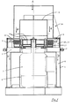
- FIG. 1 shows an overall view of a first embodiment of the crusher to explain the basic structure.
- a cylindrical housing 1 is anchored in a foundation (not shown) by means of brackets 2 distributed over the circumference.
- a drive motor 3 is arranged centrally on yoke-like radial struts 7.
- On the axis of this electric motor 3 there are two support disks 4 as a holder for breakers 5.
- the breakers 5 are preferably cast from two different steel alloys. In their rear area, which is covered by the support disks 4, they consist of a low-alloy, machinable steel, whereas their front part consists of a tough, high-alloy steel.
- a distribution plate 10 is arranged above the crushing hammer level, from which the ground material falls over a defined circumference into the annular crushing zone.
- the distribution plate 10 can be adjustable in height.
- a baffle zone is provided radially outside the crushing hammers 5 for receiving the material thrown off by the hammers.
- this is an annular insert 6 arranged in the housing, which carries radially oriented baffle plates 12 or 13 for the regrind pieces thrown off by the breakers 5 and forms the impact zone. Their function is explained in detail with reference to FIGS. 2 to 4. The insert 6 rests on the radial struts 7.
- annular removal channel 8 On the outside of the motor 3, an annular removal channel 8 is provided for the comminuted material. Located below the engine a fan wheel (not shown). Air ducts 9 are arranged along the motor 3 in order to guide its cooling air along the cooling fins of the motor and to separate it from the air backflow. The flow of the millbase through the mill is indicated by arrow lines.
- a shoulder 17 is arranged under the revolving plane of the breaking hammers, on which a bed of regrind is built up. If a piece of regrind falls on this shoulder between the hammers 5, it is gripped by the next hammer 5.
- baffle plates 12 and 13 On the outside of the orbit of the breakers, stationary, essentially radially oriented baffle plates 12 and 13 are now arranged standing (see FIG. 4), onto which the grist fragments with their tangential speed to meet.
- This second impact against the baffle plates 12 and 13 made of hardened steel results in a second reduction in the size of the material to be ground, which then falls downward from the baffle plates by gravity into the annular discharge channel 8 (see arrow D in FIG. 1).
- the crushing plates thus remain free of regrind and continuously offer a hard impact surface.
- the grinding material is thus crushed in exactly two defined steps, the grinding material flow through the crusher following a hollow cylindrical path.
- the large effective area that can be achieved with this allows a large material throughput with a high breaking effect.
- the baffle plate insert 6 can be seen in different designs from FIGS. 2 to 4. It has, in particular, standing baffle plates 12 and 13, which e.g. are distributed over the circumference at angular intervals of 30 °.
- the optimal orientation of the baffle plates is to ensure that the pieces of ground material meet approximately at right angles.
- the baffle plates 12 are designed according to the embodiment of FIGS. 2 and 3 as angles, the baffle surfaces 14 of which are angled in such a way that the regrind pieces strike approximately at right angles. Since the crusher, as will be explained, is operated in both directions of rotation, such baffles 14 are formed on both sides accordingly.
- baffle plates 13 are arranged at an angular distance (of 30 °) so that the direct impact of the ground material on the outer wall 15 of the insert 6 is avoided.
- the symmetrical arrangement of the baffle plates with respect to the direction of rotation of the breakers 5 also allows reversing here the direction of rotation, as indicated by arrows in FIG. 4.
- the baffle plates 13 are also adjustable in the radial direction, whereby the breaking characteristic can be optimized. A distance of 30 - 40 mm between the outer edge of the breakers and the baffle plates has proven to be favorable.
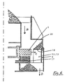
- FIG. 6 shows a modified version of the crusher from FIG. 1.
- the distance of the horizontal housing wall 20 from the crushing zone is increased.
- a cover 18 is provided above the baffle plates approximately at the level of the crushing hammers 5.
- the regrind that arrives there is fed inward over the material cone to the grinding track and, if it exceeds a certain grain size, is gripped by the breakers 5.
- the height position of the cover 18 is adjustable with respect to the revolving plane of the breakers 5, e.g. by lifting the flapper insert 6.
- the radial distance between the cover 18 and the breakers 5 gives a measure of the maximum grain size that is generated in the crusher.
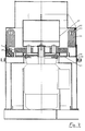
- FIG. 7 shows a further embodiment of the crusher according to the invention.
- several crushing hammers 21 are suspended in the impact zone as impact plates. They form the baffles against which the regrind pieces thrown off by the rotating breakers 5 impact.
- the breakers 21 suspended in this way are the same components which are also used for the rotating breakers 5. This reduces the number of different components, but above all offers the advantage that crushing hammers worn in the rotor can still be used as impact elements. This significantly reduces the cost of operating the crusher.
- approximately twelve stationary breakers 21 are suspended at regular intervals from plate-shaped holding elements 22 which are guided through the fastening holes 23 of the hammers.
- the hammers 21 forming the baffles are arranged radially outside and above the rotating breakers 5 in the embodiment according to FIG.
- the reason for this is that, depending on the working conditions (speed of rotation and wear of the hammers 5, falling speed of the regrind, etc.), a large part of the fragments thrown away by the hammers 5 have an upward speed component. Therefore, it may be useful to have the baffles and baffle plates 12, 13 respectively. arrange the stationary hammers 21 so that they are at least partially higher than the hammers 5. To evenly wear out the impact surfaces, it can also be useful to arrange the height of the baffles. This also makes it possible to adapt the position of the baffle plates to the respective working conditions.
- the maximum regrind size is essentially defined by the width of the gap 26 which is formed between the shoulders 17 and 24.
- old hammers can be placed in other parts of the crusher that are subject to heavy wear. For example, many fragments that bounce out of the impact zone hit the wall 27. To protect this wall, it can be lined with old breakers or replaced with old breakers.
- Old breakers can also be used to protect or replace other wall areas.
- the rotating breakers 5 are subject to considerable wear, even if they are made from an abrasion-resistant alloy.
- the crusher according to the invention especially the front upper edge in the circumferential direction is particularly heavily worn.
- FIG. 5 shows the corresponding wear of a crushing hammer 5 shown in cross section in four phases of its service life. First, as shown on the left in FIG. 5, by reversing the direction of rotation, after some operating time both upper edges of the breaker are worn out. Then it is turned, whereby the two upper edges are again worn in the same way.
- the breakers 5 can be used optimally. This results in a significant cost advantage compared to conventional crushers.
- Another advantage is the compact design of the crusher, measured by its throughput capacity, which is made possible by the processing of the ground material distributed over the circumference.
- the crusher is essentially made up of two parts.
- a base part 1 with a drive motor and breakers is anchored in a foundation.
- the holder for the hammers 21 used as baffles are removably on the base part.
- the periodic exchange of the breakers is simplified by merely lifting the inlet part 26 of the breaker in order to get to the breakers.
Landscapes
- Engineering & Computer Science (AREA)
- Food Science & Technology (AREA)
- Crushing And Pulverization Processes (AREA)
Priority Applications (1)
| Application Number | Priority Date | Filing Date | Title |
|---|---|---|---|
| US08/025,958 US5381974A (en) | 1992-03-25 | 1993-03-03 | Crusher |
Applications Claiming Priority (2)
| Application Number | Priority Date | Filing Date | Title |
|---|---|---|---|
| CH945/92 | 1992-03-25 | ||
| CH94592 | 1992-03-25 |
Publications (2)
| Publication Number | Publication Date |
|---|---|
| EP0562163A2 true EP0562163A2 (fr) | 1993-09-29 |
| EP0562163A3 EP0562163A3 (fr) | 1994-03-09 |
Family
ID=4198826
Family Applications (1)
| Application Number | Title | Priority Date | Filing Date |
|---|---|---|---|
| EP92119007A Withdrawn EP0562163A2 (fr) | 1992-03-25 | 1992-11-06 | Broyeur |
Country Status (1)
| Country | Link |
|---|---|
| EP (1) | EP0562163A2 (fr) |
Cited By (3)
| Publication number | Priority date | Publication date | Assignee | Title |
|---|---|---|---|---|
| EP0835690A1 (fr) | 1996-10-11 | 1998-04-15 | Van der Zanden, Johannes Petrus Andreas Josephus | Procédé et dispositif de broyage par la collision synchronisée de matériau |
| CN110976025A (zh) * | 2019-12-20 | 2020-04-10 | 浙江鼎峰科技股份有限公司 | 一种制砂机以及制砂系统 |
| CN115178343A (zh) * | 2022-08-03 | 2022-10-14 | 江苏江龙新材料科技有限公司 | 一种石墨电极生产用原料破碎装置 |
Citations (7)
| Publication number | Priority date | Publication date | Assignee | Title |
|---|---|---|---|---|
| DE2811376A1 (de) * | 1978-03-16 | 1979-09-20 | Hazemag Andreas Kg | Rotir fuer prallmuehlen, insbesondere fuer sandprallmuehlen |
| EP0261913A2 (fr) * | 1986-09-22 | 1988-03-30 | Nordberg Inc. | Broyeur à impact à axe vertical ayant un anneau de broyage à segments interchangeables |
| DE8810234U1 (fr) * | 1988-08-12 | 1988-09-22 | Torfwerk Gebr. Brill Gmbh & Co. Kg, 4458 Georgsdorf, De | |
| SU1431833A1 (ru) * | 1987-03-30 | 1988-10-23 | Всесоюзный государственный научно-исследовательский и проектный институт асбестовой промышленности | Дробилка ударно-истирающего действи |
| US4819886A (en) * | 1988-01-06 | 1989-04-11 | Lambert Gene F | Rotary hammer mill for breaking stone and similar material |
| DE3935882A1 (de) * | 1989-10-27 | 1991-05-02 | Vladimir Zinovievic Leikin | Zerkleinerungsvorrichtung |
| EP0477812A1 (fr) * | 1990-09-24 | 1992-04-01 | Martin H. Gygi | Broyeur |
-
1992
- 1992-11-06 EP EP92119007A patent/EP0562163A2/fr not_active Withdrawn
Patent Citations (7)
| Publication number | Priority date | Publication date | Assignee | Title |
|---|---|---|---|---|
| DE2811376A1 (de) * | 1978-03-16 | 1979-09-20 | Hazemag Andreas Kg | Rotir fuer prallmuehlen, insbesondere fuer sandprallmuehlen |
| EP0261913A2 (fr) * | 1986-09-22 | 1988-03-30 | Nordberg Inc. | Broyeur à impact à axe vertical ayant un anneau de broyage à segments interchangeables |
| SU1431833A1 (ru) * | 1987-03-30 | 1988-10-23 | Всесоюзный государственный научно-исследовательский и проектный институт асбестовой промышленности | Дробилка ударно-истирающего действи |
| US4819886A (en) * | 1988-01-06 | 1989-04-11 | Lambert Gene F | Rotary hammer mill for breaking stone and similar material |
| DE8810234U1 (fr) * | 1988-08-12 | 1988-09-22 | Torfwerk Gebr. Brill Gmbh & Co. Kg, 4458 Georgsdorf, De | |
| DE3935882A1 (de) * | 1989-10-27 | 1991-05-02 | Vladimir Zinovievic Leikin | Zerkleinerungsvorrichtung |
| EP0477812A1 (fr) * | 1990-09-24 | 1992-04-01 | Martin H. Gygi | Broyeur |
Cited By (4)
| Publication number | Priority date | Publication date | Assignee | Title |
|---|---|---|---|---|
| EP0835690A1 (fr) | 1996-10-11 | 1998-04-15 | Van der Zanden, Johannes Petrus Andreas Josephus | Procédé et dispositif de broyage par la collision synchronisée de matériau |
| CN110976025A (zh) * | 2019-12-20 | 2020-04-10 | 浙江鼎峰科技股份有限公司 | 一种制砂机以及制砂系统 |
| CN115178343A (zh) * | 2022-08-03 | 2022-10-14 | 江苏江龙新材料科技有限公司 | 一种石墨电极生产用原料破碎装置 |
| CN115178343B (zh) * | 2022-08-03 | 2023-11-03 | 江苏江龙新材料科技有限公司 | 一种石墨电极生产用原料破碎装置 |
Also Published As
| Publication number | Publication date |
|---|---|
| EP0562163A3 (fr) | 1994-03-09 |
Similar Documents
| Publication | Publication Date | Title |
|---|---|---|
| EP1536892B1 (fr) | Dispositif de broyage | |
| EP2851122B1 (fr) | Dispositif de concassage | |
| EP2529835B1 (fr) | Dispositif destiné à la séparation mécanique de conglomérats de matière à partir de matières de différentes épaisseurs et/ou consistances | |
| WO2013167398A1 (fr) | Dispositif de fractionnement | |
| EP0374491B1 (fr) | Séparateur pneumatique | |
| DE3821360C2 (fr) | ||
| DE3802260C2 (fr) | ||
| EP1957199B1 (fr) | Concasseur a plaques de percussion et a deux rotors | |
| DE3823380C2 (de) | Sichter zum Sichten von körnigem, insbesondere agglomeriertem Gut | |
| DE3935882A1 (de) | Zerkleinerungsvorrichtung | |
| DE112017003304T5 (de) | Prallbrecher mit vertikaler Welle | |
| EP0562163A2 (fr) | Broyeur | |
| DE19723705C1 (de) | Mühle zum schonenden Feinstvermahlen von Produkten unterschiedlicher Herkunft | |
| DE2620797C2 (de) | Schlägermühle zur Aufbereitung von faserhaltigen Produkten | |
| DE19835144C2 (de) | Gasdurchströmte Zerkleinerungsmaschine mit rotierendem Schlagradsystem | |
| DE3138259C2 (fr) | ||
| DE845007C (de) | Schlagkreuzmuehle | |
| EP2548648B1 (fr) | Broyeur pour le broyage de matière | |
| EP0556645B1 (fr) | Broyeur à marteaux | |
| DE3442133A1 (de) | Zentrifugalschlagbrecheinrichtung | |
| DE102014216453A1 (de) | Rotor | |
| EP3498378B1 (fr) | Revêtement d'espace intérieur et son procédé de fabrication | |
| DE1288888B (de) | Vorrichtung zum Mahlen von stueckigem Gut | |
| EP0477812A1 (fr) | Broyeur | |
| DE830604C (de) | Prallmuehle, insbesondere zum Mahlen von Weizen und anderem Getreide |
Legal Events
| Date | Code | Title | Description |
|---|---|---|---|
| PUAI | Public reference made under article 153(3) epc to a published international application that has entered the european phase |
Free format text: ORIGINAL CODE: 0009012 |
|
| AK | Designated contracting states |
Kind code of ref document: A2 Designated state(s): AT BE CH DE DK ES FR GB GR IE IT LI LU NL SE |
|
| PUAL | Search report despatched |
Free format text: ORIGINAL CODE: 0009013 |
|
| AK | Designated contracting states |
Kind code of ref document: A3 Designated state(s): AT BE CH DE DK ES FR GB GR IE IT LI LU NL SE |
|
| 17P | Request for examination filed |
Effective date: 19940701 |
|
| GRAG | Despatch of communication of intention to grant |
Free format text: ORIGINAL CODE: EPIDOS AGRA |
|
| 17Q | First examination report despatched |
Effective date: 19960328 |
|
| GRAH | Despatch of communication of intention to grant a patent |
Free format text: ORIGINAL CODE: EPIDOS IGRA |
|
| STAA | Information on the status of an ep patent application or granted ep patent |
Free format text: STATUS: THE APPLICATION IS DEEMED TO BE WITHDRAWN |
|
| 18D | Application deemed to be withdrawn |
Effective date: 19961126 |