EP0561887B1 - Verbesserte abwasserbehandlung - Google Patents
Verbesserte abwasserbehandlung Download PDFInfo
- Publication number
- EP0561887B1 EP0561887B1 EP19920900536 EP92900536A EP0561887B1 EP 0561887 B1 EP0561887 B1 EP 0561887B1 EP 19920900536 EP19920900536 EP 19920900536 EP 92900536 A EP92900536 A EP 92900536A EP 0561887 B1 EP0561887 B1 EP 0561887B1
- Authority
- EP
- European Patent Office
- Prior art keywords
- rbc
- chamber
- waste water
- section
- upstream
- Prior art date
- Legal status (The legal status is an assumption and is not a legal conclusion. Google has not performed a legal analysis and makes no representation as to the accuracy of the status listed.)
- Expired - Lifetime
Links
- 238000004065 wastewater treatment Methods 0.000 title claims description 4
- 238000011144 upstream manufacturing Methods 0.000 claims abstract description 48
- 239000002351 wastewater Substances 0.000 claims abstract description 32
- 239000003864 humus Substances 0.000 claims abstract description 14
- XLYOFNOQVPJJNP-UHFFFAOYSA-N water Substances O XLYOFNOQVPJJNP-UHFFFAOYSA-N 0.000 claims abstract description 9
- 238000000034 method Methods 0.000 claims description 21
- 239000007788 liquid Substances 0.000 claims description 18
- 239000002028 Biomass Substances 0.000 claims description 12
- 239000010802 sludge Substances 0.000 claims description 12
- 238000007599 discharging Methods 0.000 claims description 4
- 239000007787 solid Substances 0.000 claims description 4
- 230000000737 periodic effect Effects 0.000 claims description 3
- 231100000331 toxic Toxicity 0.000 abstract description 3
- 230000002588 toxic effect Effects 0.000 abstract description 3
- 239000000126 substance Substances 0.000 description 6
- 239000010865 sewage Substances 0.000 description 5
- IJGRMHOSHXDMSA-UHFFFAOYSA-N Atomic nitrogen Chemical compound N#N IJGRMHOSHXDMSA-UHFFFAOYSA-N 0.000 description 4
- 239000003139 biocide Substances 0.000 description 4
- 244000005700 microbiome Species 0.000 description 4
- 239000003440 toxic substance Substances 0.000 description 4
- QVGXLLKOCUKJST-UHFFFAOYSA-N atomic oxygen Chemical compound [O] QVGXLLKOCUKJST-UHFFFAOYSA-N 0.000 description 3
- 230000003115 biocidal effect Effects 0.000 description 3
- 230000005764 inhibitory process Effects 0.000 description 3
- 230000003647 oxidation Effects 0.000 description 3
- 238000007254 oxidation reaction Methods 0.000 description 3
- 239000001301 oxygen Substances 0.000 description 3
- 229910052760 oxygen Inorganic materials 0.000 description 3
- 241000894006 Bacteria Species 0.000 description 2
- 238000006065 biodegradation reaction Methods 0.000 description 2
- 231100000481 chemical toxicant Toxicity 0.000 description 2
- 238000004140 cleaning Methods 0.000 description 2
- 230000012010 growth Effects 0.000 description 2
- 230000014759 maintenance of location Effects 0.000 description 2
- 239000000463 material Substances 0.000 description 2
- 229910052757 nitrogen Inorganic materials 0.000 description 2
- 231100000614 poison Toxicity 0.000 description 2
- 239000002253 acid Substances 0.000 description 1
- 230000006978 adaptation Effects 0.000 description 1
- 230000015556 catabolic process Effects 0.000 description 1
- 239000012459 cleaning agent Substances 0.000 description 1
- 238000007596 consolidation process Methods 0.000 description 1
- 230000007423 decrease Effects 0.000 description 1
- 238000006731 degradation reaction Methods 0.000 description 1
- 230000006866 deterioration Effects 0.000 description 1
- 230000001627 detrimental effect Effects 0.000 description 1
- 230000029087 digestion Effects 0.000 description 1
- 238000010790 dilution Methods 0.000 description 1
- 239000012895 dilution Substances 0.000 description 1
- 230000000694 effects Effects 0.000 description 1
- 239000003344 environmental pollutant Substances 0.000 description 1
- 230000002706 hydrostatic effect Effects 0.000 description 1
- 230000002401 inhibitory effect Effects 0.000 description 1
- 238000011081 inoculation Methods 0.000 description 1
- 239000011344 liquid material Substances 0.000 description 1
- 230000007774 longterm Effects 0.000 description 1
- 239000000203 mixture Substances 0.000 description 1
- 230000002572 peristaltic effect Effects 0.000 description 1
- 230000002085 persistent effect Effects 0.000 description 1
- 231100000719 pollutant Toxicity 0.000 description 1
- 239000008213 purified water Substances 0.000 description 1
- 230000035939 shock Effects 0.000 description 1
- 239000011343 solid material Substances 0.000 description 1
- 231100000419 toxicity Toxicity 0.000 description 1
- 230000001988 toxicity Effects 0.000 description 1
- 238000005406 washing Methods 0.000 description 1
- 239000002699 waste material Substances 0.000 description 1
Images

Classifications
-
- C—CHEMISTRY; METALLURGY
- C02—TREATMENT OF WATER, WASTE WATER, SEWAGE, OR SLUDGE
- C02F—TREATMENT OF WATER, WASTE WATER, SEWAGE, OR SLUDGE
- C02F1/00—Treatment of water, waste water, or sewage
- C02F1/006—Water distributors either inside a treatment tank or directing the water to several treatment tanks; Water treatment plants incorporating these distributors, with or without chemical or biological tanks
-
- C—CHEMISTRY; METALLURGY
- C02—TREATMENT OF WATER, WASTE WATER, SEWAGE, OR SLUDGE
- C02F—TREATMENT OF WATER, WASTE WATER, SEWAGE, OR SLUDGE
- C02F3/00—Biological treatment of water, waste water, or sewage
- C02F3/02—Aerobic processes
- C02F3/08—Aerobic processes using moving contact bodies
- C02F3/082—Rotating biological contactors
-
- Y—GENERAL TAGGING OF NEW TECHNOLOGICAL DEVELOPMENTS; GENERAL TAGGING OF CROSS-SECTIONAL TECHNOLOGIES SPANNING OVER SEVERAL SECTIONS OF THE IPC; TECHNICAL SUBJECTS COVERED BY FORMER USPC CROSS-REFERENCE ART COLLECTIONS [XRACs] AND DIGESTS
- Y02—TECHNOLOGIES OR APPLICATIONS FOR MITIGATION OR ADAPTATION AGAINST CLIMATE CHANGE
- Y02W—CLIMATE CHANGE MITIGATION TECHNOLOGIES RELATED TO WASTEWATER TREATMENT OR WASTE MANAGEMENT
- Y02W10/00—Technologies for wastewater treatment
- Y02W10/10—Biological treatment of water, waste water, or sewage
Definitions
- This invention relates to an improved method of treating waste water containing biodegradable matter and to improved plant for implementing the method.
- waste water is led to the RBC from an upstream primary settlement tank and leaves the RBC to flow into a final settlement tank from which, now purified of at least the biodegradable material and suspended solids, it flows on to the environment.
- GB-A-2119357, EP-A-0161077 and US-A-4729828 all disclose waste water treatment apparatus in which treatment is effected in at least two biological stages each containing a rotating biological contactor but there is no suggestion in any of these documents that the upstream one of these two stages forms a part of a flow-balancing chamber for the apparatus.
- the plant By arranging for a biological contactor to form a part of the flow-balancing chamber, the plant is able to cope with waste water flows that at least occasionally contain toxic substances that do inhibit the capacity of the biomass to treat the biodegradable matter in the waste water. Because a minor part of the biomass available on the RBC is located in the flow-balancing chamber, this minor part can, if occasion requires, act sacrificially to absorb, or at least reduce, the toxicity and thereby prevent the flow of toxic substances into contact with the major part of the biomass on the RBC.
- the invention is equally applicable to a compact integrated sewage treatment plant designed to serve a single house (e.g. a "Biodisc” (RTM) plant having an RBC media bank housed in one tank with upstream primary and downstream settlement tanks) up to a large-scale treatment plant designed to serve a community of more than 1000 people where a septic (primary settlement) tank is likely to be provided separate from the RBC which in turn is separated from a humus or final settlement tank.
- a septic (primary settlement) tank is likely to be provided separate from the RBC which in turn is separated from a humus or final settlement tank.
- the invention involves feeding a chamber containing a rotating biological contactor (RBC) with waste water from an inlet tank and discharging from the RBC-containing chamber into a humus tank, the RBC being divided into separated upstream and downstream sections, the chamber containing the downstream section being fed with water to be processed at a controlled rate from the chamber containing the upstream section and a balancing chamber is provided for isolating the downstream section of the RBC from variations in flow of waste water to the inlet tank, characterised in that the upstream section of the RBC forms part of the balancing chamber.
- RBC rotating biological contactor
- the upstream section represents less than 50% of the total biomass support area of the RBC.
- the upstream section is between 20% and 40% of the total biomass support area and suitably around 30%.
- the inlet tank is divided into an upstream section which receives the waste water and is maintained at a constant water level and a downstream section which is part of the balancing chamber and is hydraulically linked to the chamber containing the upstream section of the RBC.
- the downstream section of the inlet tank and the linked chamber containing the upstream section of the RBC vary in liquid level as inlet flow fluctuates from hour to hour and day to day while the upstream section of the inlet tank and the chamber containing the downstream end of the RBC remain at respective substantially constant liquid levels.
- the humus tank may include a sump into which solids will settle as sludge and the method may include periodic removal of the settled humus sludge to an upstream point in the waste water treatment (e.g. to the primary settlement tank) or to a point facilitating removal from the plant.
- the invention comprises an RBC rotating in a chamber fed from an inlet tank and discharging to a humus tank, the RBC chamber being divided into separated upstream and downstream sections, and is characterised in that the upstream section of the RBC chamber forms part of a flow-balancing chamber for the apparatus.
- the inlet tank is also divided into upstream and downstream sections, the upstream section of the RBC chamber and the downstream section of the inlet tank together forming the balancing chamber.
- a liquid lift means can be provided between the sections of the RBC which is actuated by the rotational motion of the RBC (e.g. by the provision of cups or the like on the RBC) but an Archimedean screw, peristaltic pump, air lift pump or electric pump could also be used.
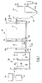
- a primary settlement tank 10 is divided by a weir 11 into a first stage chamber 12 and a second stage chamber 13.
- An RBC 15 is divided into an upstream rotor section 15A constituting some 30% of the available biomass support areas and a downstream rotor section 15B providing the remaining 70%.
- Sections 15A and 15B are rotatably supported in separated RBC chambers 16 and 17, respectively. Both rotor sections are driven by the same motor 18 and section 15A includes at least one bucket 19 on its downstream end to lift a measured volume of liquid out of chamber 16 and to discharge it into chamber 17 once each 360° rotation of rotor section 15A.
- Chambers 16 and 13 are linked by a duct 20 allowing flow of liquid from chamber 13 to chamber 16.
- a humus tank 21 Downstream of chamber 17 is a humus tank 21, the latter being shaped to provide a sludge sump 21a from which an output pipe 22 leads to a sludge accumulating tank 23 or to an upstream part of the plant e.g. the tank 10.
- An inlet for waste water into the plant is shown at 25 and an outlet for purified water is shown at 26.
- the liquid levels throughout the plant will be as shown by the dotted level lines 30 to 34.
- the liquid level is constantly at level 30 set by the weir 11.
- the liquid levels are constant respectively at 31 and 32 and are set by the level of an outlet 27 from the chamber 17 and the pipe 26 (or outlet weir) from tank 21.
- the liquid level can vary anywhere between lines 33 and 34 due to the fact that flow into chamber 13 is related to the rate at which inlet waste water flows into chamber 12, whereas the outflow rate from chamber 16 is constant provided the RBC section 15A is rotating at a constant rate and providing the level in chamber 16 is not close to the lower level limit 34.
- Levels 30, 33, 31 and 32 could be the same, but need not be.
- the drawing shows (in chain lines) a link 35 between a bottom part of the chamber 16 and the chamber 12 and this can be useful for passing sludge which drops off the rotor section 15A back into the tank 10 e.g. via the inlet 25.
- the upstream section 15A of the RBC which is housed in the chamber 16 forms the upstream part of a biozone and this further contributes to the process in the following manner:
- a farm-based RBC conventional treatment plant which received waste water from a domestic dwelling 36 (average flow 1000 litres/day) and a milking parlour 37 (average flow 100 - 150 litres/day) was found to deteriorate in performance over a ten week cycle.
- the BOD (biological oxygen demand) of the treated water discharged from the plant outlet 26 was 30 ppm (30 mg/litre) but this gradually increased to 100 ppm over a period of a few weeks.
- Cleaning out the plant and restarting saw a return to the acceptable initial ⁇ 30 ppm figure but again a steady deterioration of performance set in over the following weeks requiring yet another clean-out of the plant when the efficiency again became unacceptable.
- chemicals in the waste water from the milking parlour 37 e.g. to name one, M.I. acid
- the waste water from the milking parlour 37 and the domestic sewage from the dwelling 36 were both discharged into the first stage chamber 12 of the septic tank 10.
- the clarified mixed liquid then discharged over the weir 11 into the second stage chamber 13 of the septic tank which now acts as part of a balancing chamber.
- the first stage 15A of the RBC is separated from the second stage 15B by a fixed baffle 38.
- the second stage chamber 13 of the septic tank 10 being linked with the upstream chamber 16 of the RBC hydraulically at a lower submerged level via the duct 20, acts together as the balancing chamber for the plant.
- the balanced flow is transferred from the upstream RBC chamber 16 to the downstream RBC chamber 17 using the bucket(s) 19. In the example given, this rate would be of the order of a forward feed rate of 1.2 litres/min..
- the first section 15A of the RBC acts to condition the sewage and will overcome any partial inhibition which may occur because of biocides persisting in the flow through duct 20.
- the hydraulic and chemical balancing which occurs in chambers 13 and 16 will enable the second section 15B of the RBC to operate in a plug flow mode at the desired mass BOD loading rate (in the example given a rate of approximately 3 gms/m 2 /day).
- the controlled flow throughput in chamber 17 increases retention time in the RBC thus taking care of the low velocity constant and also enables the humus tank 21 to operate at an almost constant flow.
- baffle 39 can be provided adjacent to the inlet 25.
- the rotational speed of the RBC should be set (e.g. at 2 rpm) to avoid excess oxygen in the bulk liquid in chamber 17. This is to create oxygen-limiting conditions in the bulk liquor and provide oxidation of the pollutants in the biofilm on the rotor section 15B rather than the creation of mixed liquid suspended growths.
- the humus tank 21 serves as a proper settling tank which facilitates consolidation of sludge and its effective removal via the pipe 22.
- a desludging operation can be carried out by timer controlled, pump-assisted hydrostatic means (not shown).
- the sludge recovered from the pipe 22 could be removed from the plant at intervals but could be returned to the septic tank 10 if desired.
- the plant receiving the output from 36 and 37 operated in steady state conditions with less than 30 ppm BOD in the discharged liquid.
- Figure 1 shows a plant with separated primary tank 10, chambers 16, 17 and humus tank 21, the invention can equally well be applied to integrated plant (such as that known under our Registered Trade mark "BIODISC") in which a single tank is sectioned to provide interconnected volumes 10, 16, 17 and 21 and such a tank is shown in Figure 2.
- BIODISC Registered Trade mark
- a slot 40 is provided in chamber 16 to allow sludge dropping off the rotor section 15A to pass back into the volume 10.
Landscapes
- Life Sciences & Earth Sciences (AREA)
- Hydrology & Water Resources (AREA)
- Engineering & Computer Science (AREA)
- Environmental & Geological Engineering (AREA)
- Water Supply & Treatment (AREA)
- Chemical & Material Sciences (AREA)
- Organic Chemistry (AREA)
- Biological Treatment Of Waste Water (AREA)
- Water Treatment By Sorption (AREA)
- Physical Water Treatments (AREA)
- Removal Of Specific Substances (AREA)
- Purification Treatments By Anaerobic Or Anaerobic And Aerobic Bacteria Or Animals (AREA)
- Solid-Sorbent Or Filter-Aiding Compositions (AREA)
- Separation Using Semi-Permeable Membranes (AREA)
- Pharmaceuticals Containing Other Organic And Inorganic Compounds (AREA)
- Acyclic And Carbocyclic Compounds In Medicinal Compositions (AREA)
- Excavating Of Shafts Or Tunnels (AREA)
- Water Treatment By Electricity Or Magnetism (AREA)
- Auxiliary Devices For And Details Of Packaging Control (AREA)
- Driving Mechanisms And Operating Circuits Of Arc-Extinguishing High-Tension Switches (AREA)
- Load-Engaging Elements For Cranes (AREA)
- Separation Of Suspended Particles By Flocculating Agents (AREA)
Claims (10)
- Verfahren zur Verarbeitung von biologisch abbaubare Stoffe enthaltendem Abwasser, bei dem man Abwasser aus einem Eingangstank (10) einer Kammer (16, 17) mit einem rotierenden biologischen Kontaktor (RBK) (15) zuführt und daraus in einen Humustank (21) ableitet, wobei der RBK in getrennte stromaufwärtige (15A) und stromabwärtige (15B) Abschnitte unterteilt ist, wobei der Kammer (17) mit dem stromabwärtigen Abschnitt (15B) zu verarbeitendes Wasser in geregelter Menge aus der Kammer (16) mit dem stromaufwärtigen Abschnitt (15A) zugeführt wird und eine Ausgleichskammer (13) zur Isolierung des stromabwärtigen Abschnitts (15B) des RBK von Schwankungen der Abwasserströmung in den Eingangstank (10) vorgesehen ist, dadurch gekennzeichnet, daß der stromaufwärtige Abschnitt (15A) des RBK einen Teil der Ausgleichskammer (13, 20, 16) bildet.
- Verfahren nach Anspruch 1, dadurch gekennzeichnet, daß der stromaufwärtige Abschnitt (15A) weniger als 50% der gesamten Biomasse tragenden Fläche des RBK (15) darstellt.
- Verfahren nach Anspruch 2, dadurch gekennzeichnet, daß der stromaufwärtige Abschnitt (15A) zwischen 20% und 40% der gesamten Biomasse tragenden Fläche ausmacht.
- Verfahren nach Anspruch 3, dadurch gekennzeichnet, daß der stromaufwärtige Abschnitt (15A) ungefähr 30% der gesamten Biomasse tragenden Fläche ausmacht.
- Verfahren nach einem der vorhergehenden Ansprüche, dadurch gekennzeichnet, daß der Eingangstank (10) in einen stromaufwärtigen Abschnitt (12), der das Abwasser empfängt und auf konstantem Wasserniveau (30) gehalten wird, und einen stromabwärtigen Abschnitt (13), der einen Teil der Ausgleichskammer (13, 20, 16) darstellt und hydraulisch mit der Kammer (16) mit dem stromaufwärtigen Abschnitt (15A) des RBK verbunden ist, unterteilt ist.
- Verfahren nach einem der vorhergehenden Ansprüche, dadurch gekennzeichnet, daß der Humustank (21) einen Sumpf (21a) einschließt, in den sich Feststoffe absetzen, und daß das Verfahren periodische Entfernung des abgesetzten Humusschlamms zu einer stromaufwärtigen Stelle in der Abwasserbehandlung umfaßt.
- Verfahren nach Anspruch 6, dadurch gekennzeichnet, daß der entfernte Schlamm zu dem stromaufwärtigen Abschnitt (12) des Eingangstanks (10) zurückgeführt wird.
- Anlage zur Verarbeitung von biologisch abbaubare Stoffe enthaltendem Abwasser, umfassend einen rotierenden biologischen Kontaktor (RBK) (15), der in einer Kammer (16, 17) mit Zufuhr aus einem Eingangstank (10) und Ableitung zu einem Humustank (21) rotiert, wobei die RBK-Kammer in getrennte stromaufwärtige (16) und stromabwärtige (17) Abschnitte und eine Ausgleichskammer zur Isolierung des stromabwärtigen Abschnitts (15B) des RBK von Schwankungen der Wasserströmung in den Eingangstank (10) unterteilt ist, dadurch gekennzeichnet, daß der stromaufwärtige Abschnitt (16) der RBK-Kammer einen Teil der besagten strömungsausgleichenden Kammer (13, 20, 16) für die Anlage bildet.
- Anlage nach Anspruch 8, in der eine Flüssigkeitshebevorrichtung (19) zwischen den Abschnitten (15A, 15B) des RBK vorgesehen ist, dadurch gekennzeichnet, daß die Hebevorrichtung (19) durch die Rotationsbewegung des RBK in Gang gesetzt wird.
- Anlage nach Anspruch 9, dadurch gekennzeichnet, daß Becher oder dergleichen an den RBK angebracht sind, um Flüssigkeit aus einem stromaufwärtigen Abschnitt (16) zu einem stromabwärtigen Abschnitt (17) der RBK-Kammer zu heben.
Applications Claiming Priority (3)
| Application Number | Priority Date | Filing Date | Title |
|---|---|---|---|
| GB9026787 | 1990-12-10 | ||
| GB9026787A GB9026787D0 (en) | 1990-12-10 | 1990-12-10 | Improved waste water treatment |
| PCT/GB1991/002172 WO1992010431A1 (en) | 1990-12-10 | 1991-12-06 | Improved waste water treatment |
Publications (2)
| Publication Number | Publication Date |
|---|---|
| EP0561887A1 EP0561887A1 (de) | 1993-09-29 |
| EP0561887B1 true EP0561887B1 (de) | 1996-07-17 |
Family
ID=10686756
Family Applications (1)
| Application Number | Title | Priority Date | Filing Date |
|---|---|---|---|
| EP19920900536 Expired - Lifetime EP0561887B1 (de) | 1990-12-10 | 1991-12-06 | Verbesserte abwasserbehandlung |
Country Status (15)
| Country | Link |
|---|---|
| US (1) | US5407578A (de) |
| EP (1) | EP0561887B1 (de) |
| AT (1) | ATE140439T1 (de) |
| AU (1) | AU650083B2 (de) |
| BR (1) | BR9107261A (de) |
| CA (1) | CA2097917C (de) |
| DE (1) | DE69120965T2 (de) |
| DK (1) | DK0561887T3 (de) |
| ES (1) | ES2090593T3 (de) |
| FI (1) | FI103404B (de) |
| GB (1) | GB9026787D0 (de) |
| GR (1) | GR3021046T3 (de) |
| HU (1) | HU213698B (de) |
| NO (1) | NO303979B1 (de) |
| WO (1) | WO1992010431A1 (de) |
Families Citing this family (12)
| Publication number | Priority date | Publication date | Assignee | Title |
|---|---|---|---|---|
| GB9306226D0 (en) * | 1993-03-25 | 1993-05-19 | Graesser Contractors Ltd | Means for continuous digestion of organic matter |
| US5733456A (en) * | 1997-03-31 | 1998-03-31 | Okey; Robert W. | Environmental control for biological nutrient removal in water/wastewater treatment |
| US7156986B2 (en) * | 2003-11-26 | 2007-01-02 | Warrow Theodore U | Self-cleansing media for rotating biological contactors |
| US7879232B2 (en) * | 2005-10-27 | 2011-02-01 | Waste Stream Technologies, Llc | Double-sided self-cleansing media |
| US7811449B2 (en) * | 2005-10-27 | 2010-10-12 | Waste Stream Technologies, Llc | Flow equalized rotating biological contactor |
| WO2009124383A1 (en) * | 2008-04-07 | 2009-10-15 | Société Eg06 Inc. | Decentralized source separation sewage system |
| US8460548B2 (en) | 2010-12-16 | 2013-06-11 | Biomass Technologies, Llc | Rotating biological contactor apparatus and method |
| US9133042B2 (en) | 2010-12-16 | 2015-09-15 | Biomass Technologies, Llc | Rotating biological contactor apparatus and method |
| US20150041393A1 (en) * | 2011-09-12 | 2015-02-12 | William G. Smith | Method and apparatus for treatment of wastewater |
| WO2013103289A1 (es) | 2012-01-03 | 2013-07-11 | Valdes Simancas Farncisco Xavier | Rotor biológico de contacto de alta capacidad |
| US10145355B2 (en) * | 2016-07-04 | 2018-12-04 | Bioturbine Systems Inc. | Gas-liquid turbine and method of driving same |
| US12595199B2 (en) | 2022-04-26 | 2026-04-07 | James Robert Kiner | Rotating biological contactor media and shaft/load transfer mechanism |
Family Cites Families (8)
| Publication number | Priority date | Publication date | Assignee | Title |
|---|---|---|---|---|
| US3428555A (en) * | 1966-01-10 | 1969-02-18 | Hitachi Chemical Co Ltd | Method and an apparatus for purifying waste |
| DE1958247C3 (de) * | 1969-11-20 | 1975-10-23 | Johann Conrad 7200 Tuttlingen Stengelin | Biologische Abwasserkläranlage |
| FR2323640A1 (fr) * | 1975-09-15 | 1977-04-08 | Teba Sa | Procede de traitement des eaux usees et dispositif pour l'application de ce procede |
| DE3208173A1 (de) * | 1982-03-06 | 1983-09-08 | Volker Dipl.-Ing. 7200 Tuttlingen Stengelin | Verfahren und vorrichtung zum entfernen des stickstoffs aus dem abwasser mittels tauchtropfkoerper |
| US4468326A (en) * | 1982-06-29 | 1984-08-28 | Jorgen Jolner | Process in microbiological purification and a device and materials therefor |
| EP0161077A1 (de) * | 1984-04-11 | 1985-11-13 | Rota-Disc Pty. Limited | Abwasserbehandlung |
| US4729828A (en) * | 1986-12-29 | 1988-03-08 | Gary Miller | Modular rotating biological contactor system |
| US5248422A (en) * | 1992-05-28 | 1993-09-28 | Neu Kenneth E | Process for treating wastewater to remove BOD and nutrients |
-
1990
- 1990-12-10 GB GB9026787A patent/GB9026787D0/en active Pending
-
1991
- 1991-12-06 AU AU90608/91A patent/AU650083B2/en not_active Ceased
- 1991-12-06 HU HU9301610A patent/HU213698B/hu not_active IP Right Cessation
- 1991-12-06 EP EP19920900536 patent/EP0561887B1/de not_active Expired - Lifetime
- 1991-12-06 WO PCT/GB1991/002172 patent/WO1992010431A1/en not_active Ceased
- 1991-12-06 AT AT92900536T patent/ATE140439T1/de not_active IP Right Cessation
- 1991-12-06 ES ES92900536T patent/ES2090593T3/es not_active Expired - Lifetime
- 1991-12-06 DK DK92900536T patent/DK0561887T3/da active
- 1991-12-06 US US08/070,398 patent/US5407578A/en not_active Expired - Lifetime
- 1991-12-06 CA CA 2097917 patent/CA2097917C/en not_active Expired - Lifetime
- 1991-12-06 BR BR9107261A patent/BR9107261A/pt not_active IP Right Cessation
- 1991-12-06 DE DE69120965T patent/DE69120965T2/de not_active Expired - Lifetime
-
1993
- 1993-06-08 NO NO932084A patent/NO303979B1/no not_active IP Right Cessation
- 1993-06-09 FI FI932634A patent/FI103404B/fi active
-
1996
- 1996-09-13 GR GR960402409T patent/GR3021046T3/el unknown
Also Published As
| Publication number | Publication date |
|---|---|
| EP0561887A1 (de) | 1993-09-29 |
| AU9060891A (en) | 1992-07-08 |
| ES2090593T3 (es) | 1996-10-16 |
| GB9026787D0 (en) | 1991-01-30 |
| HU213698B (en) | 1997-09-29 |
| FI932634L (fi) | 1993-06-09 |
| FI103404B1 (fi) | 1999-06-30 |
| DE69120965T2 (de) | 1997-02-06 |
| NO303979B1 (no) | 1998-10-05 |
| NO932084D0 (no) | 1993-06-08 |
| GR3021046T3 (en) | 1996-12-31 |
| ATE140439T1 (de) | 1996-08-15 |
| WO1992010431A1 (en) | 1992-06-25 |
| NO932084L (no) | 1993-06-08 |
| DE69120965D1 (de) | 1996-08-22 |
| AU650083B2 (en) | 1994-06-09 |
| HU9301610D0 (en) | 1993-11-29 |
| FI103404B (fi) | 1999-06-30 |
| FI932634A0 (fi) | 1993-06-09 |
| CA2097917C (en) | 1999-08-10 |
| BR9107261A (pt) | 1994-04-19 |
| US5407578A (en) | 1995-04-18 |
| HUT71426A (en) | 1995-11-28 |
| DK0561887T3 (da) | 1996-11-25 |
Similar Documents
| Publication | Publication Date | Title |
|---|---|---|
| EP0561887B1 (de) | Verbesserte abwasserbehandlung | |
| US5868172A (en) | Flow augmenting device for a wastewater treatment plant | |
| CN218561237U (zh) | 一种用于施工期污水处理的模块化组合装置 | |
| CA2550018A1 (en) | Active biological contactor (abc): a modular wastewater treatment system | |
| US10604429B2 (en) | System and method for treating wastewater | |
| KR20030059178A (ko) | 개선된 고형물 저감 기능을 가지는 폐수 처리 장치 및 방법 | |
| Ismaeel | Designing a decentralized sewage treatment plant | |
| RU2225368C1 (ru) | Способ глубокой биологической очистки сточных вод и станция глубокой биологической очистки сточных вод | |
| RU2698694C1 (ru) | Способ аэробной биологической очистки сточных вод взвешенным активным илом с гидроавтоматическим режимом регулирования скорости рециркуляции в зависимости от единовременных объемов неравномерно подаваемых сточных вод частных домов и специальным ночным режимом денитрификации и устройство для его осуществления | |
| AU2006298434A1 (en) | Method and system for treating organically contaminated waste water | |
| CN117720223B (zh) | 一种污水处理系统 | |
| RU2260568C1 (ru) | Очистная установка для сточных вод коттеджей | |
| CN212246662U (zh) | 一种五金制品含乳化液废水处理系统 | |
| JPH05261386A (ja) | 回分式汚水処理方法における余剰汚泥の処理方法とその処理装置 | |
| SU1011556A1 (ru) | Устройство дл очистки сточных вод | |
| WO1994007802A1 (en) | Odour controlled waste water treatment system | |
| Bernal et al. | Using membrane bioreactors for wastewater treatment for small communities | |
| US11214504B2 (en) | Bio-DAF system for domestic and industrial wastewater treatment | |
| SU1263651A1 (ru) | Аэротенк Б.Н.Репина | |
| RU2299864C1 (ru) | Способ очистки сточных вод | |
| KR200344882Y1 (ko) | 질소와 인을 제거하기 위한 고도처리 시스템 | |
| SU889629A1 (ru) | Устройство дл очистки сточных вод | |
| WO2026069154A1 (en) | A waste water treatment system and a method for waste water treatment | |
| SU1691322A1 (ru) | Способ биохимической очистки сточных вод | |
| PLANT | Technews |
Legal Events
| Date | Code | Title | Description |
|---|---|---|---|
| PUAI | Public reference made under article 153(3) epc to a published international application that has entered the european phase |
Free format text: ORIGINAL CODE: 0009012 |
|
| 17P | Request for examination filed |
Effective date: 19930618 |
|
| AK | Designated contracting states |
Kind code of ref document: A1 Designated state(s): AT BE CH DE DK ES FR GB GR IT LI LU MC NL SE |
|
| 17Q | First examination report despatched |
Effective date: 19950116 |
|
| GRAH | Despatch of communication of intention to grant a patent |
Free format text: ORIGINAL CODE: EPIDOS IGRA |
|
| GRAH | Despatch of communication of intention to grant a patent |
Free format text: ORIGINAL CODE: EPIDOS IGRA |
|
| GRAA | (expected) grant |
Free format text: ORIGINAL CODE: 0009210 |
|
| AK | Designated contracting states |
Kind code of ref document: B1 Designated state(s): AT BE CH DE DK ES FR GB GR IT LI LU MC NL SE |
|
| REF | Corresponds to: |
Ref document number: 140439 Country of ref document: AT Date of ref document: 19960815 Kind code of ref document: T |
|
| REF | Corresponds to: |
Ref document number: 69120965 Country of ref document: DE Date of ref document: 19960822 |
|
| REG | Reference to a national code |
Ref country code: CH Ref legal event code: NV Representative=s name: A. BRAUN, BRAUN, HERITIER, ESCHMANN AG PATENTANWAE |
|
| ITF | It: translation for a ep patent filed | ||
| REG | Reference to a national code |
Ref country code: ES Ref legal event code: FG2A Ref document number: 2090593 Country of ref document: ES Kind code of ref document: T3 |
|
| ET | Fr: translation filed | ||
| REG | Reference to a national code |
Ref country code: ES Ref legal event code: FG2A Ref document number: 2090593 Country of ref document: ES Kind code of ref document: T3 |
|
| REG | Reference to a national code |
Ref country code: DK Ref legal event code: T3 |
|
| REG | Reference to a national code |
Ref country code: GR Ref legal event code: FG4A Free format text: 3021046 |
|
| PLBE | No opposition filed within time limit |
Free format text: ORIGINAL CODE: 0009261 |
|
| STAA | Information on the status of an ep patent application or granted ep patent |
Free format text: STATUS: NO OPPOSITION FILED WITHIN TIME LIMIT |
|
| 26N | No opposition filed | ||
| PGFP | Annual fee paid to national office [announced via postgrant information from national office to epo] |
Ref country code: MC Payment date: 20001213 Year of fee payment: 10 |
|
| PGFP | Annual fee paid to national office [announced via postgrant information from national office to epo] |
Ref country code: DK Payment date: 20001215 Year of fee payment: 10 Ref country code: GR Payment date: 20001215 Year of fee payment: 10 |
|
| PGFP | Annual fee paid to national office [announced via postgrant information from national office to epo] |
Ref country code: ES Payment date: 20001220 Year of fee payment: 10 |
|
| PGFP | Annual fee paid to national office [announced via postgrant information from national office to epo] |
Ref country code: FR Payment date: 20001221 Year of fee payment: 10 Ref country code: BE Payment date: 20001221 Year of fee payment: 10 |
|
| PGFP | Annual fee paid to national office [announced via postgrant information from national office to epo] |
Ref country code: LU Payment date: 20001222 Year of fee payment: 10 |
|
| PGFP | Annual fee paid to national office [announced via postgrant information from national office to epo] |
Ref country code: NL Payment date: 20001231 Year of fee payment: 10 |
|
| PG25 | Lapsed in a contracting state [announced via postgrant information from national office to epo] |
Ref country code: MC Free format text: LAPSE BECAUSE OF NON-PAYMENT OF DUE FEES Effective date: 20011206 Ref country code: LU Free format text: LAPSE BECAUSE OF NON-PAYMENT OF DUE FEES Effective date: 20011206 Ref country code: DK Free format text: LAPSE BECAUSE OF NON-PAYMENT OF DUE FEES Effective date: 20011206 |
|
| PG25 | Lapsed in a contracting state [announced via postgrant information from national office to epo] |
Ref country code: GR Free format text: LAPSE BECAUSE OF NON-PAYMENT OF DUE FEES Effective date: 20011231 Ref country code: BE Free format text: LAPSE BECAUSE OF NON-PAYMENT OF DUE FEES Effective date: 20011231 |
|
| REG | Reference to a national code |
Ref country code: GB Ref legal event code: IF02 |
|
| BERE | Be: lapsed |
Owner name: KLARGESTER ENVIRONMENTAL ENGINEERING LTD Effective date: 20011231 |
|
| PG25 | Lapsed in a contracting state [announced via postgrant information from national office to epo] |
Ref country code: NL Free format text: LAPSE BECAUSE OF NON-PAYMENT OF DUE FEES Effective date: 20020701 |
|
| PG25 | Lapsed in a contracting state [announced via postgrant information from national office to epo] |
Ref country code: FR Free format text: LAPSE BECAUSE OF NON-PAYMENT OF DUE FEES Effective date: 20020830 |
|
| NLV4 | Nl: lapsed or anulled due to non-payment of the annual fee |
Effective date: 20020701 |
|
| REG | Reference to a national code |
Ref country code: DK Ref legal event code: EBP |
|
| REG | Reference to a national code |
Ref country code: FR Ref legal event code: ST |
|
| REG | Reference to a national code |
Ref country code: GB Ref legal event code: 732E |
|
| PG25 | Lapsed in a contracting state [announced via postgrant information from national office to epo] |
Ref country code: ES Free format text: LAPSE BECAUSE OF NON-PAYMENT OF DUE FEES Effective date: 20021207 |
|
| REG | Reference to a national code |
Ref country code: CH Ref legal event code: PUE Owner name: KEE PROCESS LIMITED TRANSFER- KLARGESTER ENVIRONME Ref country code: CH Ref legal event code: PFA Free format text: KLARGESTER ENVIRONMENTAL ENGINEERING LIMITED TRANSFER- KEE PROCESS LIMITED |
|
| REG | Reference to a national code |
Ref country code: ES Ref legal event code: FD2A Effective date: 20030113 |
|
| PG25 | Lapsed in a contracting state [announced via postgrant information from national office to epo] |
Ref country code: IT Free format text: LAPSE BECAUSE OF NON-PAYMENT OF DUE FEES;WARNING: LAPSES OF ITALIAN PATENTS WITH EFFECTIVE DATE BEFORE 2007 MAY HAVE OCCURRED AT ANY TIME BEFORE 2007. THE CORRECT EFFECTIVE DATE MAY BE DIFFERENT FROM THE ONE RECORDED. Effective date: 20051206 |
|
| REG | Reference to a national code |
Ref country code: CH Ref legal event code: PFA Owner name: KLARGESTER ENVIRONMENTAL LIMITED Free format text: KLARGESTER ENVIRONMENTAL LIMITED#COLLEGE ROAD ASTON CLINTON#AYLESBURY, BUCKINGHAMSHIRE HP22 5EW (GB) -TRANSFER TO- KLARGESTER ENVIRONMENTAL LIMITED#COLLEGE ROAD ASTON CLINTON#AYLESBURY, BUCKINGHAMSHIRE HP22 5EW (GB) |
|
| PGFP | Annual fee paid to national office [announced via postgrant information from national office to epo] |
Ref country code: AT Payment date: 20101005 Year of fee payment: 20 |
|
| PGFP | Annual fee paid to national office [announced via postgrant information from national office to epo] |
Ref country code: CH Payment date: 20101223 Year of fee payment: 20 |
|
| PGFP | Annual fee paid to national office [announced via postgrant information from national office to epo] |
Ref country code: GB Payment date: 20101018 Year of fee payment: 20 Ref country code: SE Payment date: 20101213 Year of fee payment: 20 |
|
| PGFP | Annual fee paid to national office [announced via postgrant information from national office to epo] |
Ref country code: DE Payment date: 20101229 Year of fee payment: 20 |
|
| REG | Reference to a national code |
Ref country code: DE Ref legal event code: R071 Ref document number: 69120965 Country of ref document: DE |
|
| REG | Reference to a national code |
Ref country code: DE Ref legal event code: R071 Ref document number: 69120965 Country of ref document: DE |
|
| REG | Reference to a national code |
Ref country code: CH Ref legal event code: PL |
|
| REG | Reference to a national code |
Ref country code: GB Ref legal event code: PE20 Expiry date: 20111205 |
|
| REG | Reference to a national code |
Ref country code: SE Ref legal event code: EUG |
|
| PG25 | Lapsed in a contracting state [announced via postgrant information from national office to epo] |
Ref country code: GB Free format text: LAPSE BECAUSE OF EXPIRATION OF PROTECTION Effective date: 20111205 |
|
| REG | Reference to a national code |
Ref country code: AT Ref legal event code: MK07 Ref document number: 140439 Country of ref document: AT Kind code of ref document: T Effective date: 20111206 |
|
| PG25 | Lapsed in a contracting state [announced via postgrant information from national office to epo] |
Ref country code: DE Free format text: LAPSE BECAUSE OF EXPIRATION OF PROTECTION Effective date: 20111207 |