EP0561887B1 - Improved waste water treatment - Google Patents
Improved waste water treatment Download PDFInfo
- Publication number
- EP0561887B1 EP0561887B1 EP19920900536 EP92900536A EP0561887B1 EP 0561887 B1 EP0561887 B1 EP 0561887B1 EP 19920900536 EP19920900536 EP 19920900536 EP 92900536 A EP92900536 A EP 92900536A EP 0561887 B1 EP0561887 B1 EP 0561887B1
- Authority
- EP
- European Patent Office
- Prior art keywords
- rbc
- chamber
- waste water
- section
- upstream
- Prior art date
- Legal status (The legal status is an assumption and is not a legal conclusion. Google has not performed a legal analysis and makes no representation as to the accuracy of the status listed.)
- Expired - Lifetime
Links
Images

Classifications
-
- C—CHEMISTRY; METALLURGY
- C02—TREATMENT OF WATER, WASTE WATER, SEWAGE, OR SLUDGE
- C02F—TREATMENT OF WATER, WASTE WATER, SEWAGE, OR SLUDGE
- C02F1/00—Treatment of water, waste water, or sewage
- C02F1/006—Water distributors either inside a treatment tank or directing the water to several treatment tanks; Water treatment plants incorporating these distributors, with or without chemical or biological tanks
-
- C—CHEMISTRY; METALLURGY
- C02—TREATMENT OF WATER, WASTE WATER, SEWAGE, OR SLUDGE
- C02F—TREATMENT OF WATER, WASTE WATER, SEWAGE, OR SLUDGE
- C02F3/00—Biological treatment of water, waste water, or sewage
- C02F3/02—Aerobic processes
- C02F3/08—Aerobic processes using moving contact bodies
- C02F3/082—Rotating biological contactors
-
- Y—GENERAL TAGGING OF NEW TECHNOLOGICAL DEVELOPMENTS; GENERAL TAGGING OF CROSS-SECTIONAL TECHNOLOGIES SPANNING OVER SEVERAL SECTIONS OF THE IPC; TECHNICAL SUBJECTS COVERED BY FORMER USPC CROSS-REFERENCE ART COLLECTIONS [XRACs] AND DIGESTS
- Y02—TECHNOLOGIES OR APPLICATIONS FOR MITIGATION OR ADAPTATION AGAINST CLIMATE CHANGE
- Y02W—CLIMATE CHANGE MITIGATION TECHNOLOGIES RELATED TO WASTEWATER TREATMENT OR WASTE MANAGEMENT
- Y02W10/00—Technologies for wastewater treatment
- Y02W10/10—Biological treatment of water, waste water, or sewage
Definitions
- This invention relates to an improved method of treating waste water containing biodegradable matter and to improved plant for implementing the method.
- waste water is led to the RBC from an upstream primary settlement tank and leaves the RBC to flow into a final settlement tank from which, now purified of at least the biodegradable material and suspended solids, it flows on to the environment.
- GB-A-2119357, EP-A-0161077 and US-A-4729828 all disclose waste water treatment apparatus in which treatment is effected in at least two biological stages each containing a rotating biological contactor but there is no suggestion in any of these documents that the upstream one of these two stages forms a part of a flow-balancing chamber for the apparatus.
- the plant By arranging for a biological contactor to form a part of the flow-balancing chamber, the plant is able to cope with waste water flows that at least occasionally contain toxic substances that do inhibit the capacity of the biomass to treat the biodegradable matter in the waste water. Because a minor part of the biomass available on the RBC is located in the flow-balancing chamber, this minor part can, if occasion requires, act sacrificially to absorb, or at least reduce, the toxicity and thereby prevent the flow of toxic substances into contact with the major part of the biomass on the RBC.
- the invention is equally applicable to a compact integrated sewage treatment plant designed to serve a single house (e.g. a "Biodisc” (RTM) plant having an RBC media bank housed in one tank with upstream primary and downstream settlement tanks) up to a large-scale treatment plant designed to serve a community of more than 1000 people where a septic (primary settlement) tank is likely to be provided separate from the RBC which in turn is separated from a humus or final settlement tank.
- a septic (primary settlement) tank is likely to be provided separate from the RBC which in turn is separated from a humus or final settlement tank.
- the invention involves feeding a chamber containing a rotating biological contactor (RBC) with waste water from an inlet tank and discharging from the RBC-containing chamber into a humus tank, the RBC being divided into separated upstream and downstream sections, the chamber containing the downstream section being fed with water to be processed at a controlled rate from the chamber containing the upstream section and a balancing chamber is provided for isolating the downstream section of the RBC from variations in flow of waste water to the inlet tank, characterised in that the upstream section of the RBC forms part of the balancing chamber.
- RBC rotating biological contactor
- the upstream section represents less than 50% of the total biomass support area of the RBC.
- the upstream section is between 20% and 40% of the total biomass support area and suitably around 30%.
- the inlet tank is divided into an upstream section which receives the waste water and is maintained at a constant water level and a downstream section which is part of the balancing chamber and is hydraulically linked to the chamber containing the upstream section of the RBC.
- the downstream section of the inlet tank and the linked chamber containing the upstream section of the RBC vary in liquid level as inlet flow fluctuates from hour to hour and day to day while the upstream section of the inlet tank and the chamber containing the downstream end of the RBC remain at respective substantially constant liquid levels.
- the humus tank may include a sump into which solids will settle as sludge and the method may include periodic removal of the settled humus sludge to an upstream point in the waste water treatment (e.g. to the primary settlement tank) or to a point facilitating removal from the plant.
- the invention comprises an RBC rotating in a chamber fed from an inlet tank and discharging to a humus tank, the RBC chamber being divided into separated upstream and downstream sections, and is characterised in that the upstream section of the RBC chamber forms part of a flow-balancing chamber for the apparatus.
- the inlet tank is also divided into upstream and downstream sections, the upstream section of the RBC chamber and the downstream section of the inlet tank together forming the balancing chamber.
- a liquid lift means can be provided between the sections of the RBC which is actuated by the rotational motion of the RBC (e.g. by the provision of cups or the like on the RBC) but an Archimedean screw, peristaltic pump, air lift pump or electric pump could also be used.
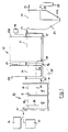
- a primary settlement tank 10 is divided by a weir 11 into a first stage chamber 12 and a second stage chamber 13.
- An RBC 15 is divided into an upstream rotor section 15A constituting some 30% of the available biomass support areas and a downstream rotor section 15B providing the remaining 70%.
- Sections 15A and 15B are rotatably supported in separated RBC chambers 16 and 17, respectively. Both rotor sections are driven by the same motor 18 and section 15A includes at least one bucket 19 on its downstream end to lift a measured volume of liquid out of chamber 16 and to discharge it into chamber 17 once each 360° rotation of rotor section 15A.
- Chambers 16 and 13 are linked by a duct 20 allowing flow of liquid from chamber 13 to chamber 16.
- a humus tank 21 Downstream of chamber 17 is a humus tank 21, the latter being shaped to provide a sludge sump 21a from which an output pipe 22 leads to a sludge accumulating tank 23 or to an upstream part of the plant e.g. the tank 10.
- An inlet for waste water into the plant is shown at 25 and an outlet for purified water is shown at 26.
- the liquid levels throughout the plant will be as shown by the dotted level lines 30 to 34.
- the liquid level is constantly at level 30 set by the weir 11.
- the liquid levels are constant respectively at 31 and 32 and are set by the level of an outlet 27 from the chamber 17 and the pipe 26 (or outlet weir) from tank 21.
- the liquid level can vary anywhere between lines 33 and 34 due to the fact that flow into chamber 13 is related to the rate at which inlet waste water flows into chamber 12, whereas the outflow rate from chamber 16 is constant provided the RBC section 15A is rotating at a constant rate and providing the level in chamber 16 is not close to the lower level limit 34.
- Levels 30, 33, 31 and 32 could be the same, but need not be.
- the drawing shows (in chain lines) a link 35 between a bottom part of the chamber 16 and the chamber 12 and this can be useful for passing sludge which drops off the rotor section 15A back into the tank 10 e.g. via the inlet 25.
- the upstream section 15A of the RBC which is housed in the chamber 16 forms the upstream part of a biozone and this further contributes to the process in the following manner:
- a farm-based RBC conventional treatment plant which received waste water from a domestic dwelling 36 (average flow 1000 litres/day) and a milking parlour 37 (average flow 100 - 150 litres/day) was found to deteriorate in performance over a ten week cycle.
- the BOD (biological oxygen demand) of the treated water discharged from the plant outlet 26 was 30 ppm (30 mg/litre) but this gradually increased to 100 ppm over a period of a few weeks.
- Cleaning out the plant and restarting saw a return to the acceptable initial ⁇ 30 ppm figure but again a steady deterioration of performance set in over the following weeks requiring yet another clean-out of the plant when the efficiency again became unacceptable.
- chemicals in the waste water from the milking parlour 37 e.g. to name one, M.I. acid
- the waste water from the milking parlour 37 and the domestic sewage from the dwelling 36 were both discharged into the first stage chamber 12 of the septic tank 10.
- the clarified mixed liquid then discharged over the weir 11 into the second stage chamber 13 of the septic tank which now acts as part of a balancing chamber.
- the first stage 15A of the RBC is separated from the second stage 15B by a fixed baffle 38.
- the second stage chamber 13 of the septic tank 10 being linked with the upstream chamber 16 of the RBC hydraulically at a lower submerged level via the duct 20, acts together as the balancing chamber for the plant.
- the balanced flow is transferred from the upstream RBC chamber 16 to the downstream RBC chamber 17 using the bucket(s) 19. In the example given, this rate would be of the order of a forward feed rate of 1.2 litres/min..
- the first section 15A of the RBC acts to condition the sewage and will overcome any partial inhibition which may occur because of biocides persisting in the flow through duct 20.
- the hydraulic and chemical balancing which occurs in chambers 13 and 16 will enable the second section 15B of the RBC to operate in a plug flow mode at the desired mass BOD loading rate (in the example given a rate of approximately 3 gms/m 2 /day).
- the controlled flow throughput in chamber 17 increases retention time in the RBC thus taking care of the low velocity constant and also enables the humus tank 21 to operate at an almost constant flow.
- baffle 39 can be provided adjacent to the inlet 25.
- the rotational speed of the RBC should be set (e.g. at 2 rpm) to avoid excess oxygen in the bulk liquid in chamber 17. This is to create oxygen-limiting conditions in the bulk liquor and provide oxidation of the pollutants in the biofilm on the rotor section 15B rather than the creation of mixed liquid suspended growths.
- the humus tank 21 serves as a proper settling tank which facilitates consolidation of sludge and its effective removal via the pipe 22.
- a desludging operation can be carried out by timer controlled, pump-assisted hydrostatic means (not shown).
- the sludge recovered from the pipe 22 could be removed from the plant at intervals but could be returned to the septic tank 10 if desired.
- the plant receiving the output from 36 and 37 operated in steady state conditions with less than 30 ppm BOD in the discharged liquid.
- Figure 1 shows a plant with separated primary tank 10, chambers 16, 17 and humus tank 21, the invention can equally well be applied to integrated plant (such as that known under our Registered Trade mark "BIODISC") in which a single tank is sectioned to provide interconnected volumes 10, 16, 17 and 21 and such a tank is shown in Figure 2.
- BIODISC Registered Trade mark
- a slot 40 is provided in chamber 16 to allow sludge dropping off the rotor section 15A to pass back into the volume 10.
Abstract
Description
- This invention relates to an improved method of treating waste water containing biodegradable matter and to improved plant for implementing the method.
- It is known to break down environmentally damaging matter in sewage or other waste water by means of bacteria (e.g. naturally-occurring microbes) and to encourage the growth of such bacteria and their digestion of the waste matter thus creating biomass layers of media of an RBC (Rotating Biological Contactor) which is supported partly in air and partly in the waste water. The RBC is slowly rotated to alternately immerse the biomass layers in the waste water and then to expose them to atmospheric oxygen.
- Normally the waste water is led to the RBC from an upstream primary settlement tank and leaves the RBC to flow into a final settlement tank from which, now purified of at least the biodegradable material and suspended solids, it flows on to the environment.
- The usual procedure is to allow plant throughput to be determined by the inflow of waste water and to dimension the treatment plant so that even on the expected maximum rate of input flow, an adequate residence time of the waste water in contact with the RBC will be obtained. Such an arrangement works well in most situations but in some extreme operating conditions (e.g. where biocidal chemicals and petrochemical-based cleaning agents may be periodically discharged in the waste water) a steady decline in operating efficiency of the plant has been noted which can only be resolved by putting the plant out of commission and cleaning out all solid and liquid material contained therein.
- GB-A-2119357, EP-A-0161077 and US-A-4729828 all disclose waste water treatment apparatus in which treatment is effected in at least two biological stages each containing a rotating biological contactor but there is no suggestion in any of these documents that the upstream one of these two stages forms a part of a flow-balancing chamber for the apparatus.
- By arranging for a biological contactor to form a part of the flow-balancing chamber, the plant is able to cope with waste water flows that at least occasionally contain toxic substances that do inhibit the capacity of the biomass to treat the biodegradable matter in the waste water. Because a minor part of the biomass available on the RBC is located in the flow-balancing chamber, this minor part can, if occasion requires, act sacrificially to absorb, or at least reduce, the toxicity and thereby prevent the flow of toxic substances into contact with the major part of the biomass on the RBC.
- We have now found that by the simple expedient of providing flow balancing at the upstream end of the RBC (and optionally also by dividing the primary settlement tank into two) it is possible to provide plug flow conditions in the downstream part of the RBC and ensure that even if a significant proportion of biocides is present in the input flow, these can be effectively diluted in the primary settlement tank thereby ensuring improved biodegradation on the RBC, i.e. conditions approaching BOD removal kinetics which are essentially first order with respect to BOD at the resulting and applied mass BOD rates per unit area of RBC media per day.
- The invention is equally applicable to a compact integrated sewage treatment plant designed to serve a single house (e.g. a "Biodisc" (RTM) plant having an RBC media bank housed in one tank with upstream primary and downstream settlement tanks) up to a large-scale treatment plant designed to serve a community of more than 1000 people where a septic (primary settlement) tank is likely to be provided separate from the RBC which in turn is separated from a humus or final settlement tank.
- In its method aspect, the invention involves feeding a chamber containing a rotating biological contactor (RBC) with waste water from an inlet tank and discharging from the RBC-containing chamber into a humus tank, the RBC being divided into separated upstream and downstream sections, the chamber containing the downstream section being fed with water to be processed at a controlled rate from the chamber containing the upstream section and a balancing chamber is provided for isolating the downstream section of the RBC from variations in flow of waste water to the inlet tank, characterised in that the upstream section of the RBC forms part of the balancing chamber.
- Suitably the upstream section represents less than 50% of the total biomass support area of the RBC. Conveniently the upstream section is between 20% and 40% of the total biomass support area and suitably around 30%.
- Conveniently the inlet tank is divided into an upstream section which receives the waste water and is maintained at a constant water level and a downstream section which is part of the balancing chamber and is hydraulically linked to the chamber containing the upstream section of the RBC. In this way the downstream section of the inlet tank and the linked chamber containing the upstream section of the RBC vary in liquid level as inlet flow fluctuates from hour to hour and day to day while the upstream section of the inlet tank and the chamber containing the downstream end of the RBC remain at respective substantially constant liquid levels.
- The humus tank may include a sump into which solids will settle as sludge and the method may include periodic removal of the settled humus sludge to an upstream point in the waste water treatment (e.g. to the primary settlement tank) or to a point facilitating removal from the plant.
- In its apparatus aspect, the invention comprises an RBC rotating in a chamber fed from an inlet tank and discharging to a humus tank, the RBC chamber being divided into separated upstream and downstream sections, and is characterised in that the upstream section of the RBC chamber forms part of a flow-balancing chamber for the apparatus. Desirably the inlet tank is also divided into upstream and downstream sections, the upstream section of the RBC chamber and the downstream section of the inlet tank together forming the balancing chamber.
- A liquid lift means can be provided between the sections of the RBC which is actuated by the rotational motion of the RBC (e.g. by the provision of cups or the like on the RBC) but an Archimedean screw, peristaltic pump, air lift pump or electric pump could also be used.
- The invention will now be further described, by way of example with reference to the accompanying drawings, in which :
- Figure 1 is a schematic sectional side elevation of a first form of plant operating in accordance with the method of the invention, and
- Figure 2 is a sectional side elevation of the invention as applied to an integrated unit.
- Referring to Figure 1, a
primary settlement tank 10 is divided by a weir 11 into afirst stage chamber 12 and a second stage chamber 13. AnRBC 15 is divided into anupstream rotor section 15A constituting some 30% of the available biomass support areas and adownstream rotor section 15B providing the remaining 70%. -
Sections RBC chambers same motor 18 andsection 15A includes at least onebucket 19 on its downstream end to lift a measured volume of liquid out ofchamber 16 and to discharge it intochamber 17 once each 360° rotation ofrotor section 15A. -
Chambers 16 and 13 are linked by aduct 20 allowing flow of liquid from chamber 13 tochamber 16. - Downstream of
chamber 17 is ahumus tank 21, the latter being shaped to provide a sludge sump 21a from which anoutput pipe 22 leads to asludge accumulating tank 23 or to an upstream part of the plant e.g. thetank 10. - An inlet for waste water into the plant is shown at 25 and an outlet for purified water is shown at 26. Under operating conditions, the liquid levels throughout the plant will be as shown by the dotted
level lines 30 to 34. - In
chamber 12 the liquid level is constantly atlevel 30 set by the weir 11. Inchamber 17 andtank 21 the liquid levels are constant respectively at 31 and 32 and are set by the level of anoutlet 27 from thechamber 17 and the pipe 26 (or outlet weir) fromtank 21. Inchambers 13 and 16, however, the liquid level can vary anywhere betweenlines chamber 12, whereas the outflow rate fromchamber 16 is constant provided theRBC section 15A is rotating at a constant rate and providing the level inchamber 16 is not close to thelower level limit 34.Levels - Controlling the levels in the manner described has a dramatic effect on the performance of the plant particularly so in the presence of periodic discharges of biocidal and petrochemical-based materials in the waste water entering the
chamber 12. It is felt that this surprising improvement in long-term efficiency in part derives from the fact thatchambers 12 and 13 serve as a septic tank and the dwell time of fresh effluent in thetank 10 under conditions of low redox oxidation potential (ROP) will reduce the toxic effect of many biocides so that when they are released from chamber 13 they have become wholly or partly degraded and diluted to the point where their toxic effect is markedly reduced thereby reducing the inhibition of the biodegradation process of the RBC in theupstream chamber 16 and certainly not causing damage to the biomass on theRBC section 15B. - The drawing shows (in chain lines) a
link 35 between a bottom part of thechamber 16 and thechamber 12 and this can be useful for passing sludge which drops off therotor section 15A back into thetank 10 e.g. via theinlet 25. - The
upstream section 15A of the RBC which is housed in thechamber 16 forms the upstream part of a biozone and this further contributes to the process in the following manner: - (a) The inhibitory effect of any toxic chemicals in the waste water which survive their dwell time in the
first stage chamber 12 will be substantially reduced or eliminated in the upstream section of the RBC. Such toxic chemicals would undergo primary biological degradation and any detrimental effect on the biochemistry will be reduced or buffered. This will enable the downstream section of the RBC to perform consistently without inhibition. - (b) The
upstream section 15A of the RBC will improve the Redox Oxidation Potential (ROP) of theentire RBC 15 by reducing or overcoming any septicity present in the liquid emanating from theseptic tank 10. - (c) The
downstream chamber 17 will receive waste water from theupstream chamber 16 at a controlled rate. The fixed film process of BOD removal on an RBC is first order with respect to BOD at low organic mass loading rates and therefore the downstream section of the RBC's efficiency is improved. Also, the velocity constants of BOD removal (BOD due to some chemicals present in waste water) are small, therefore high retention times achieved on the downstream RBC section due to balancing both chemically and hydraulically upstream of the major part of the RBC, ensures a high degree of consistent BOD removal. - (d) The fixed film process of ammoniacal nitrogen removal in the RBC is between zero and half order with respect to ammoniacal nitrogen at the low mass loading rates, and also the velocity constants are very small. The
downstream RBC section 15B is provided with stable conditions (with respect to flow rate and pollution load) for the process to operate as near the ideal conditions as possible and thereby enabling a high degree of treatment consistently. - (e) By removing and returning sludge from the
upstream chamber 16 the BOD load, due to solids, otherwise applied to the downstream RBC section, is reduced. This therefore further improves the overall process efficiency. - The following example further illustrates the invention.
- A farm-based RBC conventional treatment plant which received waste water from a domestic dwelling 36 (average flow 1000 litres/day) and a milking parlour 37 (average flow 100 - 150 litres/day) was found to deteriorate in performance over a ten week cycle. At start-up, the BOD (biological oxygen demand) of the treated water discharged from the
plant outlet 26 was 30 ppm (30 mg/litre) but this gradually increased to 100 ppm over a period of a few weeks. Cleaning out the plant and restarting saw a return to the acceptable initial <30 ppm figure but again a steady deterioration of performance set in over the following weeks requiring yet another clean-out of the plant when the efficiency again became unacceptable. It is suspected that chemicals in the waste water from the milking parlour 37 (e.g. to name one, M.I. acid) was acting as a biocide. - On converting the plant to operate in accordance with the method of this invention, the waste water from the
milking parlour 37 and the domestic sewage from thedwelling 36 were both discharged into thefirst stage chamber 12 of theseptic tank 10. The clarified mixed liquid then discharged over the weir 11 into the second stage chamber 13 of the septic tank which now acts as part of a balancing chamber. - The
first stage 15A of the RBC is separated from thesecond stage 15B by a fixedbaffle 38. The second stage chamber 13 of theseptic tank 10, being linked with theupstream chamber 16 of the RBC hydraulically at a lower submerged level via theduct 20, acts together as the balancing chamber for the plant. The balanced flow is transferred from theupstream RBC chamber 16 to thedownstream RBC chamber 17 using the bucket(s) 19. In the example given, this rate would be of the order of a forward feed rate of 1.2 litres/min.. - The
first section 15A of the RBC acts to condition the sewage and will overcome any partial inhibition which may occur because of biocides persisting in the flow throughduct 20. The hydraulic and chemical balancing which occurs inchambers 13 and 16 will enable thesecond section 15B of the RBC to operate in a plug flow mode at the desired mass BOD loading rate (in the example given a rate of approximately 3 gms/m2/day). The controlled flow throughput inchamber 17 increases retention time in the RBC thus taking care of the low velocity constant and also enables thehumus tank 21 to operate at an almost constant flow. The mixing of the domestic sewage and milking parlour waste water inchamber 12 before passing to chamber 13 ensures more uniform liquid composition and adequate dilution levels for the washing liquids fromparlour 37 before it leaves thetank 10 thus reducing the organic and chemical shock loads on even theupstream section 15A of the RBC. - To ensure good mixing of input water upstream of the weir 11, a
baffle 39 can be provided adjacent to theinlet 25. - The rotational speed of the RBC should be set (e.g. at 2 rpm) to avoid excess oxygen in the bulk liquid in
chamber 17. This is to create oxygen-limiting conditions in the bulk liquor and provide oxidation of the pollutants in the biofilm on therotor section 15B rather than the creation of mixed liquid suspended growths. - The
humus tank 21 serves as a proper settling tank which facilitates consolidation of sludge and its effective removal via thepipe 22. To avoid disturbing the settled sludge, a desludging operation can be carried out by timer controlled, pump-assisted hydrostatic means (not shown). The sludge recovered from thepipe 22 could be removed from the plant at intervals but could be returned to theseptic tank 10 if desired. - With the adaptation described, the plant receiving the output from 36 and 37 operated in steady state conditions with less than 30 ppm BOD in the discharged liquid.
- It is our knowledge that naturally occurring microorganisms can eventually adapt to even quite hostile environments,if the environment is not constantly varying. The balancing of the flows into the
RBC chamber 16 appears to enable this to be achieved. If naturally-occurring microorganisms have problems adapting to the environment, cultured adapted microorganisms with inbuilt resistance to the chemicals in the wash water can be used to inoculate the plant. However inoculation of the plant with cultured microorganisms should only rarely be necessary. - Although Figure 1 shows a plant with separated
primary tank 10,chambers humus tank 21, the invention can equally well be applied to integrated plant (such as that known under our Registered Trade mark "BIODISC") in which a single tank is sectioned to provideinterconnected volumes chamber 16 to allow sludge dropping off therotor section 15A to pass back into thevolume 10.
Claims (10)
- A method of processing waste water containing biodegradable matter which involves feeding a chamber (16, 17) containing a rotating biological contactor (RBC) (15) with waste water from an inlet tank (10) and discharging from the RBC-containing chamber (16, 17) into a humus tank (21), the RBC being divided into separated upstream (15A) and downstream (15B) sections, the chamber (17) containing the downstream section (15B) being fed with water to be processed at a controlled rate from the chamber (16) containing the upstream section (15A) and a balancing chamber (13) is provided for isolating the downstream section (15B) of the RBC from variations in flow of waste water to the inlet tank (10), characterised in that the upstream section (15A) of the RBC forms part of the balancing chamber (13, 20, 16).
- The method of claim 1, characterised in that the upstream section (15A) represents less than 50% of the total biomass support area of the RBC (15).
- The method of claim 2, characterised in that the upstream section (15A) is between 20% and 40% of the total biomass support area.
- The method of claim 3, characterised in that the upstream section (15A) is around 30% of the total biomass support area.
- The method of any preceding claim, characterised in that the inlet tank (10) is divided into an upstream section (12) which receives the waste water and is maintained at a constant water level (30) and a downstream section (13) which is part of the balancing chamber (13, 20, 16) and is hydraulically linked to the chamber (16) containing the upstream section (15A) of the RBC.
- The method of any preceding claim, characterised in that the humus tank (21) includes a sump (21a) into which solids settle and in that the method includes periodic removal of the settled humus sludge to an upstream point in the waste water treatment.
- The method of claim 6, characterised in that the removed sludge is returned to the upstream section (12) of the inlet tank (10).
- Plant for processing waste water containing biodegradable matter which plant comprises a rotating biological contactor (RBC) (15) rotating in a chamber (16, 17) fed from an inlet tank (10) and discharging to a humus tank (21), the RBC chamber being divided into separated upstream (16) and downstream (17) sections, and a balancing chamber for isolating the downstream section (15B) of the RBC from variations in flow of waste water to the inlet tank (10) characterised in that the upstream section (16) of the RBC chamber forms part of said flow-balancing chamber (13, 20, 16) for the plant.
- Plant according to claim 8, in which a liquid lift means (19) is provided between sections (15A, 15B) of the RBC, characterised in that the lift means (19) is actuated by the rotational motion of the RBC.
- Plant according to claim 9, characterised in that cups or the like are fitted on the RBC to lift liquid from an upstream section (16) to a downstream section (17) of the RBC chamber.
Applications Claiming Priority (3)
| Application Number | Priority Date | Filing Date | Title |
|---|---|---|---|
| GB9026787 | 1990-12-10 | ||
| GB9026787A GB9026787D0 (en) | 1990-12-10 | 1990-12-10 | Improved waste water treatment |
| PCT/GB1991/002172 WO1992010431A1 (en) | 1990-12-10 | 1991-12-06 | Improved waste water treatment |
Publications (2)
| Publication Number | Publication Date |
|---|---|
| EP0561887A1 EP0561887A1 (en) | 1993-09-29 |
| EP0561887B1 true EP0561887B1 (en) | 1996-07-17 |
Family
ID=10686756
Family Applications (1)
| Application Number | Title | Priority Date | Filing Date |
|---|---|---|---|
| EP19920900536 Expired - Lifetime EP0561887B1 (en) | 1990-12-10 | 1991-12-06 | Improved waste water treatment |
Country Status (15)
| Country | Link |
|---|---|
| US (1) | US5407578A (en) |
| EP (1) | EP0561887B1 (en) |
| AT (1) | ATE140439T1 (en) |
| AU (1) | AU650083B2 (en) |
| BR (1) | BR9107261A (en) |
| CA (1) | CA2097917C (en) |
| DE (1) | DE69120965T2 (en) |
| DK (1) | DK0561887T3 (en) |
| ES (1) | ES2090593T3 (en) |
| FI (1) | FI103404B (en) |
| GB (1) | GB9026787D0 (en) |
| GR (1) | GR3021046T3 (en) |
| HU (1) | HU213698B (en) |
| NO (1) | NO303979B1 (en) |
| WO (1) | WO1992010431A1 (en) |
Families Citing this family (11)
| Publication number | Priority date | Publication date | Assignee | Title |
|---|---|---|---|---|
| GB9306226D0 (en) * | 1993-03-25 | 1993-05-19 | Graesser Contractors Ltd | Means for continuous digestion of organic matter |
| US5733456A (en) * | 1997-03-31 | 1998-03-31 | Okey; Robert W. | Environmental control for biological nutrient removal in water/wastewater treatment |
| US7156986B2 (en) * | 2003-11-26 | 2007-01-02 | Warrow Theodore U | Self-cleansing media for rotating biological contactors |
| US7811449B2 (en) * | 2005-10-27 | 2010-10-12 | Waste Stream Technologies, Llc | Flow equalized rotating biological contactor |
| US7879232B2 (en) * | 2005-10-27 | 2011-02-01 | Waste Stream Technologies, Llc | Double-sided self-cleansing media |
| MX2010011061A (en) * | 2008-04-07 | 2011-04-05 | Eg06 Inc Soc | Decentralized source separation sewage system. |
| US8460548B2 (en) | 2010-12-16 | 2013-06-11 | Biomass Technologies, Llc | Rotating biological contactor apparatus and method |
| US9133042B2 (en) | 2010-12-16 | 2015-09-15 | Biomass Technologies, Llc | Rotating biological contactor apparatus and method |
| US20150041393A1 (en) * | 2011-09-12 | 2015-02-12 | William G. Smith | Method and apparatus for treatment of wastewater |
| WO2013103289A1 (en) | 2012-01-03 | 2013-07-11 | Valdes Simancas Farncisco Xavier | High-capacity biological contact rotor |
| US10145355B2 (en) * | 2016-07-04 | 2018-12-04 | Bioturbine Systems Inc. | Gas-liquid turbine and method of driving same |
Family Cites Families (8)
| Publication number | Priority date | Publication date | Assignee | Title |
|---|---|---|---|---|
| US3428555A (en) * | 1966-01-10 | 1969-02-18 | Hitachi Chemical Co Ltd | Method and an apparatus for purifying waste |
| DE1958247C3 (en) * | 1969-11-20 | 1975-10-23 | Johann Conrad 7200 Tuttlingen Stengelin | Biological sewage treatment plant |
| FR2323640A1 (en) * | 1975-09-15 | 1977-04-08 | Teba Sa | Waste waters purificn. by physical and biological treatments - using primary lagoon surge chamber to regulate peak loads |
| DE3208173A1 (en) * | 1982-03-06 | 1983-09-08 | Volker Dipl.-Ing. 7200 Tuttlingen Stengelin | METHOD AND DEVICE FOR REMOVING THE NITROGEN FROM THE WASTEWATER BY MEANS OF A DIPPED BODY |
| US4468326A (en) * | 1982-06-29 | 1984-08-28 | Jorgen Jolner | Process in microbiological purification and a device and materials therefor |
| NZ211765A (en) * | 1984-04-11 | 1987-09-30 | Rota Disc Pty Ltd | Rotating disc treatment of effluent from septic tank |
| US4729828A (en) * | 1986-12-29 | 1988-03-08 | Gary Miller | Modular rotating biological contactor system |
| US5248422A (en) * | 1992-05-28 | 1993-09-28 | Neu Kenneth E | Process for treating wastewater to remove BOD and nutrients |
-
1990
- 1990-12-10 GB GB9026787A patent/GB9026787D0/en active Pending
-
1991
- 1991-12-06 DK DK92900536T patent/DK0561887T3/en active
- 1991-12-06 BR BR9107261A patent/BR9107261A/en not_active IP Right Cessation
- 1991-12-06 CA CA 2097917 patent/CA2097917C/en not_active Expired - Lifetime
- 1991-12-06 US US08/070,398 patent/US5407578A/en not_active Expired - Lifetime
- 1991-12-06 AT AT92900536T patent/ATE140439T1/en not_active IP Right Cessation
- 1991-12-06 AU AU90608/91A patent/AU650083B2/en not_active Ceased
- 1991-12-06 EP EP19920900536 patent/EP0561887B1/en not_active Expired - Lifetime
- 1991-12-06 ES ES92900536T patent/ES2090593T3/en not_active Expired - Lifetime
- 1991-12-06 DE DE1991620965 patent/DE69120965T2/en not_active Expired - Lifetime
- 1991-12-06 HU HU9301610A patent/HU213698B/en not_active IP Right Cessation
- 1991-12-06 WO PCT/GB1991/002172 patent/WO1992010431A1/en active IP Right Grant
-
1993
- 1993-06-08 NO NO932084A patent/NO303979B1/en not_active IP Right Cessation
- 1993-06-09 FI FI932634A patent/FI103404B/en active
-
1996
- 1996-09-13 GR GR960402409T patent/GR3021046T3/en unknown
Also Published As
| Publication number | Publication date |
|---|---|
| EP0561887A1 (en) | 1993-09-29 |
| DK0561887T3 (en) | 1996-11-25 |
| CA2097917C (en) | 1999-08-10 |
| NO932084L (en) | 1993-06-08 |
| NO303979B1 (en) | 1998-10-05 |
| WO1992010431A1 (en) | 1992-06-25 |
| HU213698B (en) | 1997-09-29 |
| AU650083B2 (en) | 1994-06-09 |
| NO932084D0 (en) | 1993-06-08 |
| HUT71426A (en) | 1995-11-28 |
| AU9060891A (en) | 1992-07-08 |
| FI103404B1 (en) | 1999-06-30 |
| FI932634A0 (en) | 1993-06-09 |
| GB9026787D0 (en) | 1991-01-30 |
| ES2090593T3 (en) | 1996-10-16 |
| DE69120965D1 (en) | 1996-08-22 |
| DE69120965T2 (en) | 1997-02-06 |
| GR3021046T3 (en) | 1996-12-31 |
| US5407578A (en) | 1995-04-18 |
| BR9107261A (en) | 1994-04-19 |
| FI103404B (en) | 1999-06-30 |
| HU9301610D0 (en) | 1993-11-29 |
| ATE140439T1 (en) | 1996-08-15 |
| FI932634A (en) | 1993-06-09 |
Similar Documents
| Publication | Publication Date | Title |
|---|---|---|
| US5868172A (en) | Flow augmenting device for a wastewater treatment plant | |
| EP0561887B1 (en) | Improved waste water treatment | |
| CA2550018A1 (en) | Active biological contactor (abc): a modular wastewater treatment system | |
| CN218561237U (en) | A modularization composite set for construction period sewage treatment | |
| KR100572662B1 (en) | Dmr:(dai-ho microbe revolution) | |
| US7820048B2 (en) | Method and system for treating organically contaminated waste water | |
| KR20030059178A (en) | Apparatus and method for wastewater treatment with enhanced solids reduction(ESR) | |
| RU2698694C1 (en) | Method for aerobic biological treatment of waste water with suspended active sludge with hydro-automatic mode of recirculation rate control depending on single volumes of non-uniformly supplied waste water of private houses and special night mode of denitrification and device for its implementation | |
| US10604429B2 (en) | System and method for treating wastewater | |
| Ismaeel | Designing a Decentralized Sewage Treatment Plant | |
| RU2299864C1 (en) | Method of purification of the residential and industrial waste waters | |
| US11214504B2 (en) | Bio-DAF system for domestic and industrial wastewater treatment | |
| Bernal et al. | Using membrane bioreactors for wastewater treatment for small communities | |
| CN1276881C (en) | Membrane-flocculation sediment sewage treatment systems | |
| RU2225368C1 (en) | Method of extensive treatment of sewage and biological extensive treatment station | |
| RU2260568C1 (en) | Sewage purification installation for cottages | |
| SU1263651A1 (en) | Aerotank | |
| AU2006207887A1 (en) | Waste water treatment process | |
| SU1011556A1 (en) | Apparatus for purifying effluents | |
| WO1994007802A1 (en) | Odour controlled waste water treatment system | |
| KR200344882Y1 (en) | Advanced treatment system for removing nitrogen and phosphorus | |
| CN117720223A (en) | Sewage treatment system | |
| JP2022021699A (en) | Livestock wastewater treatment system | |
| SU889629A1 (en) | Device for waste water purification | |
| JPH05261386A (en) | Treatment of excess sludge in batch type treatment of sewage and treating equipment thereof |
Legal Events
| Date | Code | Title | Description |
|---|---|---|---|
| PUAI | Public reference made under article 153(3) epc to a published international application that has entered the european phase |
Free format text: ORIGINAL CODE: 0009012 |
|
| 17P | Request for examination filed |
Effective date: 19930618 |
|
| AK | Designated contracting states |
Kind code of ref document: A1 Designated state(s): AT BE CH DE DK ES FR GB GR IT LI LU MC NL SE |
|
| 17Q | First examination report despatched |
Effective date: 19950116 |
|
| GRAH | Despatch of communication of intention to grant a patent |
Free format text: ORIGINAL CODE: EPIDOS IGRA |
|
| GRAH | Despatch of communication of intention to grant a patent |
Free format text: ORIGINAL CODE: EPIDOS IGRA |
|
| GRAA | (expected) grant |
Free format text: ORIGINAL CODE: 0009210 |
|
| AK | Designated contracting states |
Kind code of ref document: B1 Designated state(s): AT BE CH DE DK ES FR GB GR IT LI LU MC NL SE |
|
| REF | Corresponds to: |
Ref document number: 140439 Country of ref document: AT Date of ref document: 19960815 Kind code of ref document: T |
|
| REF | Corresponds to: |
Ref document number: 69120965 Country of ref document: DE Date of ref document: 19960822 |
|
| REG | Reference to a national code |
Ref country code: CH Ref legal event code: NV Representative=s name: A. BRAUN, BRAUN, HERITIER, ESCHMANN AG PATENTANWAE |
|
| ITF | It: translation for a ep patent filed |
Owner name: INTERPATENT ST.TECN. BREV. |
|
| REG | Reference to a national code |
Ref country code: ES Ref legal event code: FG2A Ref document number: 2090593 Country of ref document: ES Kind code of ref document: T3 |
|
| ET | Fr: translation filed | ||
| REG | Reference to a national code |
Ref country code: ES Ref legal event code: FG2A Ref document number: 2090593 Country of ref document: ES Kind code of ref document: T3 |
|
| REG | Reference to a national code |
Ref country code: DK Ref legal event code: T3 |
|
| REG | Reference to a national code |
Ref country code: GR Ref legal event code: FG4A Free format text: 3021046 |
|
| PLBE | No opposition filed within time limit |
Free format text: ORIGINAL CODE: 0009261 |
|
| STAA | Information on the status of an ep patent application or granted ep patent |
Free format text: STATUS: NO OPPOSITION FILED WITHIN TIME LIMIT |
|
| 26N | No opposition filed | ||
| PGFP | Annual fee paid to national office [announced via postgrant information from national office to epo] |
Ref country code: MC Payment date: 20001213 Year of fee payment: 10 |
|
| PGFP | Annual fee paid to national office [announced via postgrant information from national office to epo] |
Ref country code: DK Payment date: 20001215 Year of fee payment: 10 Ref country code: GR Payment date: 20001215 Year of fee payment: 10 |
|
| PGFP | Annual fee paid to national office [announced via postgrant information from national office to epo] |
Ref country code: ES Payment date: 20001220 Year of fee payment: 10 |
|
| PGFP | Annual fee paid to national office [announced via postgrant information from national office to epo] |
Ref country code: FR Payment date: 20001221 Year of fee payment: 10 Ref country code: BE Payment date: 20001221 Year of fee payment: 10 |
|
| PGFP | Annual fee paid to national office [announced via postgrant information from national office to epo] |
Ref country code: LU Payment date: 20001222 Year of fee payment: 10 |
|
| PGFP | Annual fee paid to national office [announced via postgrant information from national office to epo] |
Ref country code: NL Payment date: 20001231 Year of fee payment: 10 |
|
| PG25 | Lapsed in a contracting state [announced via postgrant information from national office to epo] |
Ref country code: MC Free format text: LAPSE BECAUSE OF NON-PAYMENT OF DUE FEES Effective date: 20011206 Ref country code: LU Free format text: LAPSE BECAUSE OF NON-PAYMENT OF DUE FEES Effective date: 20011206 Ref country code: DK Free format text: LAPSE BECAUSE OF NON-PAYMENT OF DUE FEES Effective date: 20011206 |
|
| PG25 | Lapsed in a contracting state [announced via postgrant information from national office to epo] |
Ref country code: GR Free format text: LAPSE BECAUSE OF NON-PAYMENT OF DUE FEES Effective date: 20011231 Ref country code: BE Free format text: LAPSE BECAUSE OF NON-PAYMENT OF DUE FEES Effective date: 20011231 |
|
| REG | Reference to a national code |
Ref country code: GB Ref legal event code: IF02 |
|
| BERE | Be: lapsed |
Owner name: KLARGESTER ENVIRONMENTAL ENGINEERING LTD Effective date: 20011231 |
|
| PG25 | Lapsed in a contracting state [announced via postgrant information from national office to epo] |
Ref country code: NL Free format text: LAPSE BECAUSE OF NON-PAYMENT OF DUE FEES Effective date: 20020701 |
|
| PG25 | Lapsed in a contracting state [announced via postgrant information from national office to epo] |
Ref country code: FR Free format text: LAPSE BECAUSE OF NON-PAYMENT OF DUE FEES Effective date: 20020830 |
|
| NLV4 | Nl: lapsed or anulled due to non-payment of the annual fee |
Effective date: 20020701 |
|
| REG | Reference to a national code |
Ref country code: DK Ref legal event code: EBP |
|
| REG | Reference to a national code |
Ref country code: FR Ref legal event code: ST |
|
| REG | Reference to a national code |
Ref country code: GB Ref legal event code: 732E |
|
| PG25 | Lapsed in a contracting state [announced via postgrant information from national office to epo] |
Ref country code: ES Free format text: LAPSE BECAUSE OF NON-PAYMENT OF DUE FEES Effective date: 20021207 |
|
| REG | Reference to a national code |
Ref country code: CH Ref legal event code: PUE Owner name: KEE PROCESS LIMITED TRANSFER- KLARGESTER ENVIRONME Ref country code: CH Ref legal event code: PFA Free format text: KLARGESTER ENVIRONMENTAL ENGINEERING LIMITED TRANSFER- KEE PROCESS LIMITED |
|
| REG | Reference to a national code |
Ref country code: ES Ref legal event code: FD2A Effective date: 20030113 |
|
| PG25 | Lapsed in a contracting state [announced via postgrant information from national office to epo] |
Ref country code: IT Free format text: LAPSE BECAUSE OF NON-PAYMENT OF DUE FEES;WARNING: LAPSES OF ITALIAN PATENTS WITH EFFECTIVE DATE BEFORE 2007 MAY HAVE OCCURRED AT ANY TIME BEFORE 2007. THE CORRECT EFFECTIVE DATE MAY BE DIFFERENT FROM THE ONE RECORDED. Effective date: 20051206 |
|
| REG | Reference to a national code |
Ref country code: CH Ref legal event code: PFA Owner name: KLARGESTER ENVIRONMENTAL LIMITED Free format text: KLARGESTER ENVIRONMENTAL LIMITED#COLLEGE ROAD ASTON CLINTON#AYLESBURY, BUCKINGHAMSHIRE HP22 5EW (GB) -TRANSFER TO- KLARGESTER ENVIRONMENTAL LIMITED#COLLEGE ROAD ASTON CLINTON#AYLESBURY, BUCKINGHAMSHIRE HP22 5EW (GB) |
|
| PGFP | Annual fee paid to national office [announced via postgrant information from national office to epo] |
Ref country code: AT Payment date: 20101005 Year of fee payment: 20 |
|
| PGFP | Annual fee paid to national office [announced via postgrant information from national office to epo] |
Ref country code: CH Payment date: 20101223 Year of fee payment: 20 |
|
| PGFP | Annual fee paid to national office [announced via postgrant information from national office to epo] |
Ref country code: GB Payment date: 20101018 Year of fee payment: 20 Ref country code: SE Payment date: 20101213 Year of fee payment: 20 |
|
| PGFP | Annual fee paid to national office [announced via postgrant information from national office to epo] |
Ref country code: DE Payment date: 20101229 Year of fee payment: 20 |
|
| REG | Reference to a national code |
Ref country code: DE Ref legal event code: R071 Ref document number: 69120965 Country of ref document: DE |
|
| REG | Reference to a national code |
Ref country code: DE Ref legal event code: R071 Ref document number: 69120965 Country of ref document: DE |
|
| REG | Reference to a national code |
Ref country code: CH Ref legal event code: PL |
|
| REG | Reference to a national code |
Ref country code: GB Ref legal event code: PE20 Expiry date: 20111205 |
|
| REG | Reference to a national code |
Ref country code: SE Ref legal event code: EUG |
|
| PG25 | Lapsed in a contracting state [announced via postgrant information from national office to epo] |
Ref country code: GB Free format text: LAPSE BECAUSE OF EXPIRATION OF PROTECTION Effective date: 20111205 |
|
| REG | Reference to a national code |
Ref country code: AT Ref legal event code: MK07 Ref document number: 140439 Country of ref document: AT Kind code of ref document: T Effective date: 20111206 |
|
| PG25 | Lapsed in a contracting state [announced via postgrant information from national office to epo] |
Ref country code: DE Free format text: LAPSE BECAUSE OF EXPIRATION OF PROTECTION Effective date: 20111207 |