EP0561380B1 - Kettenantrieb-Mechanismus für ein Fahrrad oder dergleichen - Google Patents
Kettenantrieb-Mechanismus für ein Fahrrad oder dergleichen Download PDFInfo
- Publication number
- EP0561380B1 EP0561380B1 EP93104351A EP93104351A EP0561380B1 EP 0561380 B1 EP0561380 B1 EP 0561380B1 EP 93104351 A EP93104351 A EP 93104351A EP 93104351 A EP93104351 A EP 93104351A EP 0561380 B1 EP0561380 B1 EP 0561380B1
- Authority
- EP
- European Patent Office
- Prior art keywords
- chain
- sprocket
- driving mechanism
- set forth
- link members
- Prior art date
- Legal status (The legal status is an assumption and is not a legal conclusion. Google has not performed a legal analysis and makes no representation as to the accuracy of the status listed.)
- Expired - Lifetime
Links
Images


Classifications
-
- F—MECHANICAL ENGINEERING; LIGHTING; HEATING; WEAPONS; BLASTING
- F16—ENGINEERING ELEMENTS AND UNITS; GENERAL MEASURES FOR PRODUCING AND MAINTAINING EFFECTIVE FUNCTIONING OF MACHINES OR INSTALLATIONS; THERMAL INSULATION IN GENERAL
- F16G—BELTS, CABLES, OR ROPES, PREDOMINANTLY USED FOR DRIVING PURPOSES; CHAINS; FITTINGS PREDOMINANTLY USED THEREFOR
- F16G13/00—Chains
- F16G13/02—Driving-chains
- F16G13/04—Toothed chains
-
- B—PERFORMING OPERATIONS; TRANSPORTING
- B62—LAND VEHICLES FOR TRAVELLING OTHERWISE THAN ON RAILS
- B62M—RIDER PROPULSION OF WHEELED VEHICLES OR SLEDGES; POWERED PROPULSION OF SLEDGES OR SINGLE-TRACK CYCLES; TRANSMISSIONS SPECIALLY ADAPTED FOR SUCH VEHICLES
- B62M9/00—Transmissions characterised by use of an endless chain, belt, or the like
- B62M9/04—Transmissions characterised by use of an endless chain, belt, or the like of changeable ratio
- B62M9/06—Transmissions characterised by use of an endless chain, belt, or the like of changeable ratio using a single chain, belt, or the like
- B62M9/10—Transmissions characterised by use of an endless chain, belt, or the like of changeable ratio using a single chain, belt, or the like involving different-sized wheels, e.g. rear sprocket chain wheels selectively engaged by the chain, belt, or the like
Definitions
- the chain-side engagement means are provided by roller sleeves extending axially between adjacent link members.
- the axial middle of the chain as defined by the axial middle of the roller sleeves is axially displaced with respect to the respective sprocket such that one of the respective link members is adjacent one side of the sprocket and the other respective link member is axially spaced from the other side of the respective sprocket.
- this axial range is not defined by structural parts of the chain itself but only by the relative axial position of the chain with respect to the respective sprocket.
- the axial range is axially offset with respect to said virtual chain middle plane in a direction opposite to said axial direction, said chain being optionally provided with a further group of chain-side engagement means of conventional type.
- sprocket is to be understood in accordance with the present invention in a very general sense. It is not restricted to sprocket forms as they are used in older driving mechanisms of bicycles. This refers also to the term “a sprocket-side engagement means”. Sprocket-side engagement means should not be understood in the restricted sense of the usual teeth on older sprockets used in bicycle driving mechanisms. The same is true for chain-side engagement means. This term is also to be understood in a broad sense and is not restricted to the usual intervals between subsequent pivot bolts of usual bicycle chains.
- Chain transferring means is also to be understood in a broad sense. It covers all mechanisms useful for changing the chain between wheel-side sprocket and pedal crank-side sprockets.
- a sprocket having a maximum number of sprocket-side engagement means corresponds to, is, however, not restricted to a sprocket with a maximum number of teeth and corresponds normally to the sprocket of maximum diameter.
- a sprocket with a minumum number of sprocket engagement means corresponds to, is, however, not restricted to a smaller diameter sprocket having a smaller number of teeth of conventional design.
- chain engagement means is to be understood in a broad sense such that these chain-side engagement means are compatible with all possible types of sprocket-side engagement means.
- first and second enveloping side planes will be defined within the particular description with reference to the drawings. The same is true for a virtual chain middle plane.
- This design is basically different from older designs in which teeth of the respective sprocket engage between two subsequent roller members surrounding subsequent pivot rollers of the chain.
- a main difference is that one can allow to the projections freely selectable freedom of axial movement with respect to the respective chain engaged sprocket. This freely selectable freedom of axial movement must be obviously restricted to such a degree that an unintended displacement of the chain with respect to a predetermined sprocket cannot occur in operation.
- the freedom of axial movement is selectable much greater than with conventional chain driving mechanisms, in which the axial freedom of movement in case of a gear change is restricted to a very high and non-avoidable degree by the engagement of the sprocket teeth into intervals of the chain between subsequent pivot bolts, which intervals are on both sides confined by a link member.
- the transition of the chain from a predetermined sprocket to a newly selected sprocket can be facilitated to a high degree.
- the pocket and the projections may have - when regarded in axial direction - a substantially trapezoidal shape.
- a further possibility is to provide these projections with a triangular shape such that one point of the respective triangle is directed towards said internal loop space as defined above.
- the shape of the projections is preferably selected such that the sensitivity of the engagement conditions between chain and sprocket in dependence of varying sprocket diameter is at a minimum.
- the projections may be integral with link members of the chain, which link members may be substantially parallel to the first and second enveloping side planes. This is a feature of utmost importance, because one can give to the projections when being integral parts of such link members highly varying shapes, e. g. by stamping operation when manufacturing the link members, and one can so select the optimum engagement conditions between the pockets on the one hand and the projections on the other hand, particularly with the aim of obtaining maximum torque transmitting engagement faces and, as a result thereof, minimum engagement pressures and wear.
- the first link portion can be integral with respective projections directed toward the above defined internal loop space, and these integral projections may again be engageable with respective sprocket-side engagement means of the respective sprockets.
- the first portions of the link members can be approached to a neighbouring sprocket of larger diameter and maximum axial overlapping of the respective flank faces of the sprocket-side engagement means and the chain-side engagement means is obtained.
- the chain can be used also with conventional sprockets or e. g. in a construction in which the rear wheel sprockets are provided with sprocket-side engagement means of the present invention, and the sprocket wheels on the pedal crank shaft are provided with conventional engagement means. It is even possible to provide roller members around the engagement sections of the pivot bolts.
- a further improvement of such a chain is obtained, when a sleeve member is provided and surrounds a respective pivot bolt.
- This sleeve member may be axially shorter than the pivot bolt.
- the pivot bolt may be received by bores of the first portion of a respective cranked link member and of an outer further link member.
- a second portion of a respective cranked link member and the respective inner further link member may be provided with bores adapted to and accommodating the sleeve member.
- the sleeve member may be then used for assisting a riveting operation when fastening the pivot bolts with respect to the link members.
- the second portion of the respective link member and the inner further link member may be rotatable with respect to the sleeve member about a pivot axis.
- the chain may comprise in accordance with well known prior art a plurality of pivot bolts with a free engagement section between two axially spaced link members, such as to be engageable with usual chain sprockets having teeth for engagement between subsequent pivot bolts. These pivot bolts may be optionally surrounded by roller members.
- This design is possible with all types of chain as discussed in connection with the present invention.
- the advantage is again, as mentioned above, that the chain can be used not only in connection with sprocket-side engagement means of the present invention but also in connection with conventional sprockets having teeth engaging between subsequent pivot bolts and laterally confined by respective link members.
- the chain-side engagement means may comprise chain-side engagement studs projecting in a direction opposite to said axial direction beyond respective link members of said chain, which are axially adjacent the respective chain engaged sprocket. These engagement studs may be engageable with respective pockets at the circumferential edge of the respective sprocket.
- This embodiment allows again a maximum overlapping in axial direction of the sprocket-side engagement means and the chain-side engagement means. It further allows closest mutual approach of adjacent sprockets down to a zero distance.
- Securing means for preventing such unintended axial movement of the chain may comprise cooperating undercut means of the sprocket-side engagement means on the one hand and of the chain-side engagement means on the other hand.
- These undercut means may be wedge-shaped undercut means and/or stepped undercut means.
- the undercut means, particularly the wedge-shaped undercut means, of the chain-side engagement means and the sprocket-side engagement means may be such that the chain is urged in response to operational load in a direction opposite to the axial direction as defined above toward abutment with an abutment face.
- This abutment face may be the respective chain engaged sprocket or the subsequent sprocket of larger diameter or an intermediate disc provided side by side with a sprocket.
- the undercut means may be provided by torque transmitting flank faces of the chain engagement means and the sprocket-side engagement means, which are responsible for transmission at a normal forward driving operation.
- This design is particularly possible, when the chain-side engagement means are provided with projections as integral parts of respective link members.
- One can obtain the undercut by stamping the link members in a direction deviating from a direction orthogonal to the respective link member.
- the operational result of such a construction is that the chain is urged towards the abutment face with increasing axial force, when the chain tension is increased in response to increasing torques to be transmitted. This gives a very high security against unintended axial displacement of the chain in a most critical situation.
- the undercut means are provided between radially opposite faces of the chain engagement means and the sprocket engagement means. This is due to the fact that on loading the chain by a torque to be transmitted the linear chain tension results in radially inwards directed forces urging the chain towards the axis of the respective sprocket. These radially inwards directed forces are then responsive for maintaining engagement of the undercut means provided at radially opposite faces of the chain engagement means and the sprocket-side engagement means.
- these pins and studs may be provided with conical faces or part-conical faces for obtaining the undercut engagement.
- the present invention further considers the following problem:
- the chains applicable according to the present invention comprise pivot bolts extending in a direction opposite to said axial direction toward a neighbouring sprocket, i. e. toward a sprocket neighboured to the respective chain engaged sprocket and having a larger diameter than the respective chain engaged sprocket.
- the end portions of these pivot bolts located adjacent this neighbouring sprocket may come into contact with the neighbouring sprocket and prevent a maximum overlapping of the sprocket-side engagement means and the chain-side engagement means, if adjacent sprockets are arranged at minimum or zero axial distance.
- Another possibility of providing said engagement face zone and said bolt penetration face zone consists in giving to said respective link member a crank figuration.
- the sprocket-side engagement means comprise pockets between respective circumferentially subsequent pocket confining portions of the respective sprockets and if said chain-side engagements means comprise projections which are directed towards the internal loop space surrounded by the chains. This is particularly true, if these projections are integral with link members of the chain, which link members are substantially parallel to the plane of a chain loop.
- the application of the chain design consisting of the above discussed identic and cranked link members is applicable even, when the virtual chain middle plane is not displaced axially with respect to a respective sprocket middle plane of a sprocket drivingly engaged by the chain.
- the design comprising laterally extending engagement studs of the chain, which are engageable with respective pockets at the circumferential edge of the respective sprocket, is independent of the feature of said virtual chain middle plane being axially displaced with respect to the engaged sprocket middle plane.
- securing means preventing unintended axial disengagement of the sprocket-side engagement means and the chain-side engagement means are applicable with or without the concept of said virtual chain middle plane being axially displaced with respect to the sprocket middle plane.
- this invention relates to a bicycle drive chain comprising a plurality of link members pivotally connected with each other about respective pivot axes and at least one group of chain-side engagement means shaped for torque transmitting cooperation with sprocket-side engagement means of a sprocket unit, said chain having two enveloping side planes spaced from each other along said pivot axes, both said enveloping side planes being substantially orthogonal to said pivot axes, a virtual chain middle plane substantially orthogonal to said pivot axes being located half-way along said pivot axes between said enveloping side planes.
- the location of said at least one group of chain-side engagement means is restricted to an axial range of said chain which range is axially offset with respect to said virtual chain middle plane.
- This chain is different from the chain as disclosed in the above discussed EP 0 047 927 A2 and in the U.S. patent 2 722 843, because in the known chains the chain-side engagement means shaped for torque transmitting cooperation with a sprocket are centered with respect to the respective virtual chain middle plane.
- said at least one group of chain-side engagement means may comprise chain-side engagement studs projecting beyond link members in axial direction.
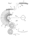
- a rear wheel sprocket unit 10 of a bicycle comprising a plurality of coaxial sprockets 12. These sprockets are connected by a free wheel unit (not shown) with a rear wheel bicycle hub of the respective bicycle. It is also possible that the sprocket unit 10 is directly fastened onto a rear wheel bicycle hub.
- a chain 14 is in driving engagement with a sprocket 12a of the sprocket unit 10. This chain 14 is simultaneously in engagement with a sprocket wheel 16 fastened on a shaft 18 of a pedal crank drive.
- the chain 14 is engageable with selective sprockets 12 of the sprocket unit 10 by a chain transferring unit which is axially movable in a direction perpendicular to the drawing plane of Fig. 1 by a switch accessible to the driver's hand and connected with the transferring unit 20 by e. g. a Bowden wire.
- a chain transferring unit 20 which is axially movable in a direction perpendicular to the drawing plane of Fig. 1 by a switch accessible to the driver's hand and connected with the transferring unit 20 by e. g. a Bowden wire.
- the chain transferring unit 20 comprises spring biased compensating means for compensating the length of the chain in accordance with the selected sprocket 12.
- the chain transferring unit 20 may be operationally connected with a further chain mover unit 22. While the chain transferring unit 20 is provided at the entrance of the chain 14 into the sprocket unit in the direction of arrow 24 corresponding to forward drive condition, the additional chain mover unit 22 is located at the exit of the chain 14 from the sprocket unit 10.
- the additional chain mover unit 22 may be synchronized for axial movement with the axial movement of the chain transferring unit 20 in a direction perpendicular to the drawing plane of Fig. 1.
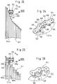
- the sprocket 12a is located between a further sprocket 12b of larger diameter and a terminal disc 26 directly adjacent the sprocket 12a. Besides the sprockets 12a and 12b a still further sprocket 12c is shown with still larger diameter.
- the sprocket 12a is provided as shown in Figs. 4 and 5b with pockets 28 between subsequent teeth 30.
- the direction of movement of the chain 14 is again designated by the arrow 24 corresponding to the arrow 24 of Fig. 1.
- the chain 14 comprises, as can be best seen from Fig. 4 and 5b, a plurality of cranked link members 34 which are cranked at 32, such as to form first link portions 34a and second link portions 34b with the first link portion 34a and the second link portion 34b of circumferentially subsequent link members 34 being circumferentially overlapped.
- the chain 14 further comprises link members 36 and 38.
- the link members are pivotally interconnected by pivot bolts 40 having pivot axes 40a. Each pivot bolt interconnects four link members, namely a first end portion 34a of a cranked link member 34, a second end portion 34b of a circumferentially adjacent link member 34, an inner link member 36 and an outer link member 38.
- the pivot bolt 40 is pressed into a bore 44 of a first end portion 34a and a bore 44' of the outer link member 38.
- a sleeve member 46 is surroundingly seated on the pivot bolt 40 and preferably non-rotatable with respect to the pivot bolt 40.
- the sleeve member 46 is helpful for riveting the pivot bolt 40 when having been brought in place as shown in Fig. 4.
- the second end portion 34b and the inner link member 36 are provided with bores 48 and 48', respectively, by which this second end portion 34b and said inner link member 36 are rotatably mounted on the sleeve member 46.
- the first end portions 34a of the link members 34 are provided with radially inward directed projections 52, which are integral with the link members 34. These projections 52 are directed towards a chain loop confined space 54, as shown in Fig. 1.
- Each projection 52 has a first torque transmitting flank face 52a and a second torque transmitting flank face 52b.
- the first torque transmitting flank face 52a is the torque transmitting flank face, when in normal forward drive operation the chain is moving along the arrow 24 and is transmitting a torque to the sprocket 12a.
- the first flank face 52a is cooperating with a first flank face 28a of the pocket 28 in the forward drive operation according to arrow 24.
- the second flank fac 52b of the projection 52 is cooperating with a flank face 28b of the pocket 28 in rearward drive operation.
- flank face 28b follows substantially the radial direction 13 while the flank face 28b defines a considerable angle of the radial line 13'. It is most important that the angle between the flank face 28a and the radial line 13 is small in order to be able to transfer high torque from the flank face 52a to the flank face 28a in forward drive condition.
- a first enveloping side plane E1 and a second enveloping side plane E2 said side planes E1 and E2 accommodating between them the total axial width of the chain 14.
- the virtual middle plane E v of the chain 14 is axially spaced from the middle plane E m of the sprocket 12a with which the chain 14 is in engagement.
- the torque transmitting flank faces 52a of the projections 52 are inclined by an angle ⁇ with respect to a reference line N which is parallel to the pivot axis 40a.
- the flank face 28a of the pocket 28 is correspondingly inclined, as one can see from the portion of the sprocket 12a indicated at the lower end of Fig. 4.
- This pocket 28 in Fig. 4 is not shown in realistic position.
- the pocket 28 receives the projection 52, i. e. the sprocket member 12a is substantially coplanar with the first end portion 34a of the link member 34. It is to be shown, however, by the sprocket 12a in Fig.
- flank face 52b of the projection 52 is inclined with an angle ⁇ against a reference line N' and that the flank 28b of the pocket 28 is inclined by the same angle ⁇ with respect to the reference line N'.
- the chain 14 is urged in the direction of arrow P toward the sprocket 12b and the sprocket 12c and is again secured against unintentional separation from the sprockets 12a.
- the projection 52 has a radially inner engagement face zone 52c engageable with an adjacent face of the neighbouring sprocket 12b.
- the link portion 34a has a pivot bolt penetration face zone 34a1 through which an end portion 40e of the pivot bolt 40 extends.
- the pivot bolt penetration face zone 34a1 is axially offset with respect to the engagement face zone 52c so that the bolt extension 40a can be riveted above the pivot bolt penetration zone 34a1 and, nevertheless, the extension 40e does not interfere with the neighbouring sprocket 12b in spite of the pivot bolt 40 being in radial overlapping position with respect to the neighbouring sprocket 12b.
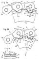
- Fig. 5a one can see the chain 14 in engagement with a sprocket 12n of larger diameter.
- the link members 34 are more straightened than in the engagement condition of Fig. 5b.
- the flank face 52a can enter again in full face contact with the flank face 28'a in forwards drive operation, and the flank face 52b can again enter into full face contact with the flank face 28'b in rearwards drive operation.
- the tip 28e of the projection 52 can abut again against the bottom 28'e of the pocket 28' under the tension in the chain 14.
- the triangular gap 28'f is the result of the modified mutual inclination of the link members 34.
- a radial line (compare radial line 13 of Fig. 5b) is larger in the case of the conditions of Fig. 5a. This is, however, acceptable due to the larger diameter of the sprocket 12n, because a greater number of engagement pockets 28' exists so that the torque to be transmitted in forwards drive operation is distributed to a larger number of pairs of flank faces 52a and 28'a.
- Fig. 3c shows that the problem of interference between the rivet head 40a and the neighbouring sprocket 12b of larger diameter does not exist, when the diameter difference of the sprockets 12a and 12b is so small that the rivet head 40e of the pivot bolts 40 are located radially outwards of the neighbouring sprocket 12b.
- This is particurlarly true for the sprockets of smaller diameter.
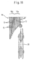
- Fig. 11 that the sprockets 12 of smaller diameter have only small differences in diameter between subsequent sprockets. This group of sprockets with smaller diameter is designated by 10a.
- Fig. 11 shows that the problem of interference between the rivet head 40a and the neighbouring sprocket 12b of larger diameter does not exist, when the diameter difference of the sprockets 12a and 12b is so small that the rivet head 40e of the pivot bolts 40 are located radially outwards of the neighbouring sprocket 12b.
- spacer discs 15 are provided between subsequent sprockets 12a and 12b.
- spacer discs 15 are provided between subsequent sprockets of the group 10b of larger diameter sprockets.
- FIG. 3e A still further possibility of avoiding interference between the rivet heads 40e and the neighbouring sprocket 12b is indicated in Fig. 3e.
- the rivet heads 40e are completely acccommodated within counter-sunk bores 44a of the link member portion 34a.
- the terminal disc 26 is provided for preventing the chain 14 to lose engagement with the sprocket 12a.
- a further terminal disc 17 is provided adjacent the maximum diameter sprocket, such as to prevent the chain 14 to move beyond the sprocket 12z of maximum diameter in an axial direction opposite to the axial direction A x .
- Fig. 7 there is shown a further type of chain using again cranked link members 134. Analogous elements of this chain are designated by the same reference numerals as in Fig. 4 increased by 100. The only difference between the embodiments of Fig. 7 and the embodiments of Fig. 4 is that according to Fig. 7, the pivot bolts 140 are shorter along the axis X-X of the sprocket unit 10 as shown in Fig. 2 and that the roller members 53 of Fig. 4 are avoided.
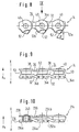
- This chain of Fig. 7 requires a sprocket wheel unit 116 as shown in Fig. 6, in which the engagement means of the various sprockets are similar or identic with the pockets 28 between subsequent "teeth" as shown in Fig. 5b.
- the chain 114 projects in the same direction A x beyond the respective engaged sprocket as in Fig. 3a.
- the virtual middle plane E v is axially displaced with respect to the middle plane E m of the respective sprocket by a distance E m - E v as in Fig. 3a.
- the sprockets of the sprocket unit 116 also decrease in diameter corresponding to the number of engagement means, when proceeding in the direction A x , this direction A x being the same direction as indicated in Fig. 3a.
- spacer discs 121 are provided, which may have a similar function as the spacer discs 15 of Fig. 3d.
- these spacer discs 121 may further have the function of partially closing pockets 119 which pockets correspond to the pockets 28 of Fig. 5b, such as to prevent the unintended disengagement of the chain 114 from the respective sprockets by axial movement in the direction A x .
- the size of the obstacle provided by the discs 121 may be selected such that, on the one hand, unintended axial movement of the chain 114 in the direction A x is prevented and, on the other hand, the intended movement of the chain 114 is not prevented more than necessary.
- Figs. 8 and 9 one can see again an elongated portion of the chain 14 with the cranked projection 52 as shown also in Fig. 3a and 3b.
- the angled ⁇ as shown in Fig. 8 corresponds to the inclination of the flank face 52a with respect to the radial line 13 as shown in Fig. 5b taking into consideration that in Fig. 8 the chain 14 is straightened, whereas in Fig. 5b it is applied to a circular sprocket 12a.
- Fig. 8 is not a realistic picture.
- the flank faces 52a and 52b are in truth invisible, because also Fig. 8 is a view in accordance to arrows V-V of Fig. 3a.
- the inclination of the flank faces 52a is such as shown in Fig. 4 and Fig. 5c. Only with such an inclination, the projection 52 of the chain 14 is moved as shown in Figs. 4 and 5c towards the neighbouring sprocket 12b in the direction P, i. e.
- the chain of Fig. 10 corresponds substantially to the design of Fig. 7. Similar parts are designated with the same reference numerals as in Fig. 7, increased, however, again by 100.
- the roller members have been avoided again so that the chain 214 has a very small axial width in the direction of the axis X-X.
- This chain can only be used, when - as shown in Fig. 6 - also the sprockets of the sprocket unit 116 are designed in accordance with one of the embodiments according to the Figs. 3a to 3e and according to Figs. 5a, 5b and 5c.
- the abutment face determining the axial position of the projection 52 of the chain 14 can also be provided by a spacer disc or by a terminal disc as shown in Fig. 6 at 121 and 123.
- the inclination of the flank faces 28a and 52a represent a dove-tail design.
- the inclinations can be very small. Due to these inclinations, a disengagement of the chain 14 in the axial direction A x is prevented also in case of shocks.
- the circumferential distance between the flank faces 28a,28b is somewhat larger than the distance between the flank faces 52a,52b such that a certain play of the projection 52 exists with respect to the pocket 28, which facilitates intended disengagement.
- both the sprockets of the rear wheel and the sprocket wheels of the pedal crank shaft with engagement means as shown in Figs. 3a, 3e and Figs. 5a to 5c and to use a chain in accordance with Fig. 7.
- This chain has the high advantage that it is very flexible with respect to flection about a flection axis F as shown in Fig. 7.
- a sprocket unit on the pedal crank shaft one has the additional advantage that also in this area, the movement of the chain between sprockets of different diameter is facilitated.
- sleeve members 146 as shown in Fig. 7 are not absolutely necessary, as one can see from Fig. 10, it is to be noted that these sleeve members 146 of Fig. 7 and 46 of Fig. 4 are very helpful also in view of maintaining lubricant within the chain.
- the difference in diameter of the bores 44,46 on the one hand, and the bores 48,50 on the other hand allows to recognize the orientation of the link members so as to facilitate automatic assembling.
- the axial width of the roller members 53 corresponds substantially to the axial distance of the link members 34 and 36 minus a certain axial play.
- the additional mover element 22 besides the chain transferring unit 20 helps to maintain the chain 14 in engagement with a selected sprocket even in rough operation.
- the chain mover 22 may be synchronized with the chain transferring unit 20.
- a further chain mover unit will be provided near the sprocket unit 16, when this sprocket unit 16 comprises a plurality of sprocket wheels.
- Such chain movers for the chain cooperating with the pedal crank shaft are well known in the art.
- the sprocket unit 16 normally comprises two or three sprocket wheels, whereas the sprocket unit 10 comprises a larger number of sprockets, e. g. 5 to 10 sprockets.
- the tension of the chain is maintained by the chain transferring unit 20 in conventional way.
- the chain transferring unit as shown in Fig. 1 can be provided with conventional idling rollers engageable with a roller chain as long as a chain type as shown in Fig. 4 is used.In case of a chain as shown in Fig. 7, it is necessary to adapt the idling rollers of the chain transferring unit 20 to the chain 114. This is easily possible.
- Sleeves 46 and 146 of Figs. 4 and 7 are helpful in the chain riveting operating. Moreover, the sleeves 146 provide a reservoir for lubricant.
- the cranked shape of the projections integral with the link member portions 34a as shown in Fig. 3b can also be replaced by a bending operation similar to teeth setting with saws.
- the width of the spacer discs 121 of Fig. 6 are selected such as to prevent a contact of the chain with the maximum diameter sprocket wheel, when the chain is simultaneously in engagement with the neighbouring sprocket wheel of smaller diameter and with a maximum diameter sprocket of the sprocket unit 10.
- While a chain mover unit for transporting the chain 14 between subsequent sprocket wheels of the sprocket unit 16 is preferably located there, where the chain in normal driving operation enters into the sprocket unit 16, it is possible to provide chain mover units adjacent the sprocket unit 16 both at the entrance of the chain 14 into the sprocket unit 16 and also at the exit of the chain from the sprocket unit 16 in an analogous way to the assistance of the chain transferring unit 20 by the chain mover unit 22.
- the chain can be securely maintained in engagement with the respective sprocket of the sprocket unit 10 and in engagement with the respective selected sprocket wheel of the sprocket wheel unit 16.
- the additional mover unit 22 has first of all a guiding function for maintaining the chain 14 in engagement with the respective selected sprocket. It is synchronized in axial direction with the axial motion of the chain transferring unit 20 for being adapted in its respective position to the selected sprocket. The same is true, if two chain mover units are allocated to the sprocket unit 16.
- Figs. 12 to 16 there is shown a further embodiment.
- a sprocket unit 310 with a plurality of sprockets 312 arranged in similar way as in Fig. 2.
- a terminal disc 317 is provided at the free side of the maximum diameter sprocket 312z, and a further terminal disc 326 is provided at the free side of the minimum diameter sprocket 312a.
- a further small diameter sprocket which is immediately neighboured to the minimum diameter sprocket 312a is designated by 312b.
- a chain 314 is in driving engagement with the sprocket 312a.
- the chain 314 has a virtual middle plane E v which is axially spaced by an axial distance E m -E v from the middle plane E m of the sprocket 312a in the axial direction A x .
- the chain is again a roller chain having roller members for engagement with conventional sprockets the teeth of which engage between circumferentially subsequent rollers 353.
- the chain comprises engagement link members 360 and interconnecting link members 361.
- the engagement link members 360 and the interconnecting link members 361 are pivotally interconnected by pivot bolts 340.
- Pockets 328 are provided at the radially outer edge of the sprocket 312a.
- a pair of subsequent pockets 328 is shaped for engagement with projections 352 which are provided at the end portions 360a,360b of the engagement link members 360.
- the projections 352 are integral with the engagement link member 360.
- the projections 352 are provided with stepped undercuts 363,which are obtained by coining, stamping or machining.
- the projections 352 are shaped for engagement into the pockets 328 of the sprocket 312a. These pockets 328 are also provided with undercuts 364 so that when the projections 352 engage into the pockets 328, the undercuts 363 engage behind the undercuts 364.
- the projections 352 are provided with flank faces 352a, which are intended for engagement with flank faces 328a of the pockets 328 so that in the normal driving operation with the chain moving in the direction 324 of Fig. 15, a torque is transmitted from the chain 314 to the sprocket 312a by the flank faces 352a engaging the flank faces 328a.
- flank faces 328a are adjacent to wedge faces 365.
- Corresponding wedge faces may be provided at the undercuts 363.
- these cooperating wedge faces one may obtain a similar result as at the inclined faces 28a and 52a as shown in Fig. 5c, namely the effect that in normal operation according to a chain movement along the arrow 324 of Fig. 15, the chain is approached to the sprocket 312b by the cooperating wedge faces.
- the cooperating undercuts 363 and 364 prevent a disengagement of the chain 314 from the sprocket 312a in the direction A x of Fig. 12.
- the pockets 328 are partially closed by the undercuts 364 in the direction A x so as to prevent unintended movement of the engagement link members 360 in the direction A x .
- the terminal disc 326 may be provided.
- the construction of the chain driving mechanism may correspond to the construction as shown in Fig. 1, particularly with respect to the pedal crank-side sprocket unit 16 and the chain mover means 20 and 22.
- this chain may again be engaged also with conventional types of sprockets and sprocket wheels, both on the rear wheel and on the pedal crank shaft.
- the degree of undercut at 363 and 364 may be selected such that on the one hand, security against unintended axial movement of the chain 314 in the direction A x is warranted and, on the other hand, an easy disengagement of the projections 352 from the pockets 328 is possible, when the chain is to be transferred to another selected sprocket.
- flank faces 352a and of the flank faces 328a are such that in driving engagement with the chain moving in the direction of arrow 324 of Fig. 15, the flank faces 352a and 328a are in substantially full face contact, such as to reduce the specific contact pressure and to reduce wear. It is easily understandable that in addition to the cooperating flank faces 328a and 352a, flank faces 352'a and 328'a may participate in torque transmission from the chain 314 to the sprocket 312a or may alone be responsible for torque transmission.
- the engagement link members 360 are also provided with flank faces 352b, which are engageable with flank faces 328b in rearwards drive operation. Analogous undercuts are allocated to this flank faces 352b and 328b as shown in Fig. 14 and 16. Also in rearwards drive operation the flank faces 352b are substantially in full face contact with the flank faces 328b.
- the terminal disc 317 prevents a movement of the chain 314 in a direction opposite to the axial direction A x beyond the sprocket 312z.
- axial movement against the direction A x of Fig. 12 may be prevented by engagement of the projections 352 with the respective neighbouring sprocket of larger diameter.
- the projections 352 may again have a certain circumferential play with respect to the pockets 328.
- the distance of the projections 352 in circumferential direction and the distance of the pockets 328a in circumferential direction are preferably selected such that both projections 352 of one engagement link member 360 can simultaneously be in torque transmission with the respective flank faces of the pockets 328.
- the rollers 353 may be avoided, if the chain is exclusively intended for engagement with sprockets of the type as shown in Fig. 13, both at the rear wheel side and at athe pedal crank side of the respective bicycle.
- the chain 314 of Figs. 12 to 16 may be replaced by a chain 414 as shown in Figs. 30 and 31. It is to be noted that with such chain 414, subsequent projections 452 are integral with subsequent cranked link members 434 similar to the link members 134 as shown in Fig. 7. Analogous parts are designated with the same reference numerals as in Fig. 7 increased, however, by 300. On recognizes that the projections 452 are again integral with the first portions 434a of the cranked link members 434, which are closer to the neighbouring sprocket having an increased diameter.
- the link members 468 are substantially in full face contact with the neighbouring sprocket of larger diameter which is designated by 412n in Fig. 18.
- the second link members 469 are also provided with projections 452' which are rectangular as the projections 452 are and which are engageable with pockets 428 of rectangular shape.
- the second link members 469 are, as one can see from Fig. 18, axially spaced from the sprocket 412m. In order to, nevertheless, provide engagement of the projections 452' into the respective pockets 428, the projections 452' are cranked at 455 against the axial direction A x , as indicated in Fig. 18. Such, also the projections 452' are substantially coplanar with the projections 452 and are axially adjacent the neighbouring sprocket 412n of larger diameter.
- the projections 452,452' are provided with inclined tip faces 470 which engage behind inclined bottom faces 471 allocated to the pockets 428.
- the projections 452,452' are urged in radially inwards direction Q as seen Fig. 19a. So, the inclined tip face 470 engages behind the equally inclined bottom face 471. On can again talk of an undercut relationship of the inclined tip and bottom faces 470,471, respectively. Such, the projections 452,452' are urged in a direction opposite to the axial direction A x into contact with the abutment provided by the neighbouring sprocket 412n. Such, an unintended axial displacement of the projections 452 and 452' with respect to the sprocket 412m in the direction A x is prevented.
- FIG. 20 A still further embodiment is shown in Fig. 20.
- a conventional chain 514 is shown for engagement with sprockets of a sprocket unit 510 as shown in Fig. 20.
- the chain 514 is in engagement with the sprocket 512m.
- the sprocket 512m is provided with pockets 528 which are are of half-conical shape.
- the pivot bolts 540 are provided adjacent their ends with conical studs 575 which are engageable with the half-conical pockets 528.
- the studs 575 are urged in radial inwards direction Q into the pockets 528.
- the studs 575 are engaged by the inclined face 570 behind the equally inclined flank face 571 of the pocket 528. Such, the stud 575 is against the direction A x of Fig. 20 approached again against the neighbouring sprocket 512n.
- the axial movement of the chain 514 opposite to the axial direction A x is limited either by engagement of a link member 576 with the sprocket 512m or by engagement of the stud end face 577 with the neighbouring sprocket 512n of increased diameter.
- the chain 514 is urged in the direction opposite to the direction A x towards the sprocket 512n.
- the unintended disengagement of the chain 514 from the sprocket 512m is prohibited at least in driving operation which may be forward or rearward.
- the chain 514 is again composed by a plurality of link members. It comprises roller members 553.
- the chain may also be restricted to a design composed of only subsequent link members as shown in Figs. 28 and 29, if an engagement with conventional sprocket or sprocket wheels is not intended. It should, however, be observed that the chain 514 should have a certain resistance against torsion about a torsional axis T as indicated in Fig. 21 for obtaining sufficient engagement force in axial direction opposite to the arrow A x in Fig. 20.
- This chain consists of first link members 668 and second link members 669.
- the first link members 668 are provided with integral projections 652 which are coplanar with the link members 668 and are, as can be seen from Fig. 23, both closest to the sprocket 612m.
- the second link members 669 are spaced from the sprocket member 612m by the axial thickness of the link members 668.
- both the link member 668 and 669 are again urged in a direction opposite to the axial direction A x towards the sprocket 612m.
- the radially inward directed force which urges the indentation 680 against the pins 681 results again from the longitudinal tension within the chain 614 both in forward drive direction and in rearward drive direction.
- a sprocket 812m of a sprocket unit 810 consists of two half sprockets 880a and 880b. Each of these half sprockets 880a, 880b is provided with a plurality of half pockets 828x and 828y. When sandwiching the half sprockets 880a and 880b, registering of pockets 828x and 828y form pockets 828 which may have different shapes, e. g. the profile shape 828 as shown in Fig. 26. These pockets 828 may cooperate with projections 828 of different types of chains, e. g. the chain 814 as shown in Fig. 26 which may again be a roller chain or a non-roller chain. According to Fig. 25, the chain 814 is a roller chain with rollers 853 for engaging a conventional sprocket.
- the axial disengagement of the chain 814 from the sprocket 812m is prevented by a wall 891 of the half pocket 828y.
- This wall may completely close the pocket 828 or define only a frame for preventing axial disengagement of the chain 814 in the axial direction A x . This may be done again with the aim to prevent on the one hand unintended disengagement of the chain 814 and to facilitate on the other hand intended disengagement of the chain 814 from a predetermined sprocket 812m to a newly selected sprocket.
- Fig. 27 shows a very important further development of the invention. It is well possible to provide a sprocket unit 910 with a sprocket unit base member 990 with a plurality sprockets 912. These sprockets 912 may be either directly shaped into the sprocket unit base member 990 or may be provided by sprocket rings of small radial width which are fastened onto the sprocket unit base member 990. In any case, each sprocket 912 may comprise a plurality of pockets 928. This embodiment is not easily to be manufactured taking into consideration that the distribution of the pockets 928 circumferential along the various sprockets is different and the shape of pockets may also be different for different sprockets.
- the undercuts as shown e. g. in the embodiment of Figs. 12 to 16 at 363 and 364 are again selected such that they provide on the one hand a sufficient security against unintended axial displacement of the chain with respect to respective sprockets in axial direction, and on the other hand allow a relative easy intended disengagement, when the chain is to be moved from a predetermined sprocket to a further selected sprocket.
- the pockets are completely closed in the direction A x of Fig. 12. In this latter case, it is necessary to lift the chain considerably, when the chain is to be moved from one sprocket to a further one.
- the chain can be extremely thin in axial direction, when the rollers for engagement with conventional sprockets are avoided.
- half sprockets 880a and 880b can be of identic shape.
- the conical pin members 681 are only half-conical for the sprockets of smaller diameter.
- the conical pins 681 do not interfere with the external diameter of the respective neighbouring sprockets of smaller diameter, even if the diameter difference between subsequent sprockets is very small.
- a further important advantage of the present invention is that chains can be used which comprise only two immediately adjacent link members of different form or cranked link members of identic shape. In both cases, the chains have an extremely small width in axial direction.
Landscapes
- Engineering & Computer Science (AREA)
- Mechanical Engineering (AREA)
- General Engineering & Computer Science (AREA)
- Chemical & Material Sciences (AREA)
- Combustion & Propulsion (AREA)
- Transportation (AREA)
- Gears, Cams (AREA)
- Devices For Conveying Motion By Means Of Endless Flexible Members (AREA)
- Transmission Devices (AREA)
- Transmissions By Endless Flexible Members (AREA)
Claims (55)
- Kettenantriebsmechanismus für ein Fahrrad oder dergleichen, umfassend eine radseitige Ritzeleinheit (10), eine pedalkurbelseitige Ritzeleinheit (16) sowie eine die Ritzeleinheiten (10,16) antriebsmäßig verbindende Kette (14), wobei zumindest eine der Ritzeleinheiten (10,16) eine Mehrzahl von Ritzen (12) aufweist, wobei die Ritzel (12) der zumindest einen Ritzeleinheit (10) entlang einer Achse (XX) seriell angeordnet sind, wobei die Mehrzahl von Ritzen (12) ein erstes Endritzel (12) mit einer maximalen Anzahl ritzelseitiger Eingriffsmittel (28) sowie ein zweites Endritzel (12) mit einer minimalen Anzahl ritzelseitiger Eingriffsmittel (28) sowie - gegebenenfalls - axial zwischen dem ersten Endritzel und dem zweiten Endritzel weitere Ritzel (12) aufweist, wobei die Anzahl ritzelseitiger Eingriffsmittel (28) der weiteren Ritzel (12) kleiner ist als die Anzahl ritzelseitiger Eingriffsmittel (28) des ersten Endritzels und größer als die Anzahl ritzelseitiger Eingriffsmittel (28) des zweiten Endritzels und wobei die Anzahl ritzelseitiger Eingriffsmittel der Ritzel in einer Axialrichtung (AX), welche von dem ersten Endritzel zu dem zweiten Endritzel weist, von Ritzel zu Ritzel abnimmt, wobei die Kette (14) durch eine Gruppe kettenseitiger Eingriffsmittel (52) wahlweise mit jeweiligen ritzelseitigen Eingriffsmitteln (28) eines jeweiligen der Ritzel (12) der zumindest einen Ritzeleinheit (10,16) in Eingriff steht, wobei Kettenüberführungsmittel (20) vorgesehen sind, um zu bewirken, daß die Kette (14) an einem gewählten der Ritzel (12) angreift, wobei jedes der Ritzel (12) eine zu der Achse (XX) ortogonale jeweilige Ritzelmittelebene (Em) aufweist, wobei die Kette (14) eine erste Hüllseitenebene (E1), und, entlang der Axialrichtung (Ax) mit Abstand von der ersten Hüllseitenebene (E1), eine zweite Hüllseitenebene (E2) aufweist, wobei beide Hüllseitenebenen (E1,E2) im wesentlichen ortogonal zu der Achse (XX) verlaufen, wobei eine zu der Achse (XX) im wesentlichen ortogonale virtuelle Kettenmittelebene (EV) auf halbem Wege entlang der Achse (XX) zwischen den Hüllseitenebenen (E1,E2) angeordnet ist, wobei die virtuelle Kettenmittelebene (EV) bezüglich einer jeweiligen Ritzelmittelebene (Em) eines von der Kette (14) antriebsmäßig ergriffenen Ritzels (12) in der Axialrichtung (Ax) axial versetzt ist, wobei die kettenseitigen Eingriffsmittel (52) der Gruppe innerhalb eines Axialbereichs der Kette (14) vorgesehen sind und bezüglich den jeweiligen ritzelseitigen Eingriffsmitteln (28) der zumindest einen Ritzeleinheit (10,16) komplementär geformt sind, wobei sich der Axialbereich zwischen durch die Kette (14) definierten Axialbereich-Begrenzungsebenen erstreckt,
dadurch gekennzeichnet, daß der Axialbereich bezüglich der virtuellen Kettenmittelebene (Ev) in einer zu der Axialrichtung (Ax) entgegengesetzten Richtung axial versetzt ist, wobei die Kette (14) gegebenenfalls mit einer weiteren Gruppe kettenseitiger Eingriffsmittel (53) herkömmlicher Bauart versehen ist. - Kettenantriebsmechanismus nach Anspruch 1,
wobei die virtuelle Kettenmittelebene(Ev) bezüglich der jeweiligen Ritzelmittelebene (Em) um einen Abstand (Em-Ev) gleich zumindest 15% des axialen Abstands der Hüllseitenebenen (E1,E2) axial versetzt ist. - Kettenantriebsmechanismus nach Anspruch 1,
wobei die virtuelle Kettenmittelebene (Ev) bezüglich der jeweiligen Ritzelmittelebene (Em) um einen Abstand (Em-Ev) gleich zumindest 30% des axialen Abstands der Hüllseitenebenen (E1,E2) axial versetzt ist. - Kettenantriebsmechanismus nach Anspruch 1,
wobei die virtuelle Kettenmittelebene (Ev) bezüglich der jeweiligen Ritzelmittelebene (Em) um einen Abstand (Em-Ev) gleich zumindest 40% des axialen Abstands der Hüllseitenebenen (E1,E2) axial versetzt ist. - Kettenantriebsmechanismus nach einem der Ansprüche 1 bis 4,
wobei die ritzelseitigen Eingriffsmittel (28) zwischen jeweiligen im Umfang aufeinander folgenden Taschenbegrenzungsabschnitten (30) des jeweiligen Ritzels (12) Taschen (28) aufweisen, wobei die Taschen (28) am radial äußeren Umfangsrand des jeweiligen Ritzels (12) in Richtung radial auswärts offen sind, wobei die kettenseitigen Eingriffsmittel (52) Vorsprünge (52) aufweisen, wobei die Vorsprünge zu einem von der Kette (14) umgebenen Schleifeninnenraum (54) weisen, wobei die Vorsprünge (52) von der Form her den Taschen (28) zum Eingriff in diese angepaßt sind, wobei die Taschen (28) zwei mit Umfangsabstand angeordnete entgegengesetzt weisende Drehmomentübertragungsflankenflächen (28a,28b) zum Drehmoment übertragenden Eingriff mit jeweiligen Flankenflächen (52a,52b) eines jeweiligen Vorsprungs (52) aufweisen. - Kettenantriebsmechanismus nach Anspruch 5,
wobei das jeweilige Ritzel (12) ein Ritzel der radseitigen Ritzeleinheit (10) ist, wobei eine der mit Umfangsabstand angeordneten Flankenflächen (28a,28b) der Tasche (28) zur Drehmomentübertragung bei normalen Vorwärtsfahrbetrieb (24) dient, wobei die eine Flankenfläche (28a) eine Richtung aufweist, die einer radialen Richtung (13) angenähert ist und die gegebenenfalls der radialen Richtung (13) weiter angenähert ist als die andere (28b) der Drehmomentübertragungsflankenflächen (im Vergleich zu der radialen Richtung (13')). - Kettenantriebsmechanismus nach einem der Ansprüche 5 oder 6,
wobei die Taschen (28) und die Vorsprünge (52) - in axialer Richtung (XX) betrachtet- eine im wesentlichen trapezoidale Form haben. - Kettenantriebsmechanismus nach einem der Ansprüche 5 oder 6,
wobei die Vorsprünge (352) eine im wesentlichen dreieckige Form haben, wobei eine Ecke der dreieckigen Form zu dem Schleifeninnenraum (54) weist. - Kettenantriebsmechanismus nach Anspruch 5 oder 6,
wobei der Vorsprung (452,452') eine im wesentlichen rechteckige Form aufweist. - Kettenantriebsmechanismus nach einem der Ansprüche 5 bis 9,
wobei die Vorsprünge (52) mit Gliedelementen (54) einstückig sind, wobei die Gliedelemente (54) zu den ersten und zweiten Hüllseitenebenen (E1,E2) im wesentlichen parallel sind. - Kettenantriebsmechanismus nach einem der Ansprüche 1 bis 10,
wobei die Kette (14) eine Gruppe im wesentlichen identischer Gliedelemente (34) aufweist, wobei die Gliedelemente (34) - betrachtet in Richtung parallel zu den Hüllseitenebenen (E1,E2) und orthogonal bezüglich einer aufeinander folgende Schwenkachsen (40a) der Kette (40) enthaltenden Ebene - derart gekröpft sind, daß jedes Gliedelement (34) der Gruppe zwei mit Umfangsabstand angeordnete und axial versetzte Gliedabschnitte aufweist, wobei ein erster Gliedabschnitt (34a) näher an der ersten Hüllseitenebene (E1) ist und ein zweiter Gliedabschnitt (34b) weiter von der ersten Hüllseitenebene (E1) entfernt ist, wobei ein erster Gliedabschnitt (34a) und ein zweiter Gliedabschnitt (34b) zweier im Umfang aufeinander folgender Gliedelemente (34) in überlappender Beziehung angeordnet und durch einen Gelenkbolzen (40) miteinander verbunden sind. - Kettenantriebsmechanismus nach Anspruch 11,
wobei die ersten Gliedabschnitte (34a) mit jeweiligen zu einem Schleifeninnenraum (54) weisenden Vorsprüngen (52) einstückig sind, wobei die Vorsprünge (52) mit jeweiligen ritzelseitigen Eingriffsmitteln (28) des jeweiligen Ritzels (12) in Eingriff zu bringen sind. - Kettenantriebsmechanismus nach Anspruch 12,
wobei die mit den Vorsprüngen (52) einstückigen ersten Gliedabschnitte (34a) bei normalem Vorwärtsfahrbetrieb (24) jeweilige vorauslaufende Abschnitte (34a) der Gliedelemente (34) sind. - Kettenantriebsmechanismus nach einem der Ansprüche 11 bis 13,
wobei die Kette eine Gruppe weiterer Gliedelemente (38,36) umfaßt, die in Umfangsrichtung zwischen aufeinander folgenden Gelenkbolzen (40) verlaufen, wobei die weiteren Gliedelemente (38,36) äußere weitere Gliedelemente (38) und innere weitere Gliedelemente (36) in abwechselnder Anordnung zwischen aufeinander folgenden Gelenkbolzen (40) aufweisen, wobei sich jeder Gelenkbolzen (40) durch ein Paar gekröpfter Gliedelemente (34) und ein Paar eines inneren weiteren Gliedelements (36) und eines äußeren weiteren Gliedelements (38) erstreckt. - Kettenantriebsmechanismus nach Anspruch 14,
wobei Rollenelemente (53) um jeweilige Bolzen (40) herum axial zwischen einem jeweiligen inneren weiteren Gliedelement (36) und einem jeweiligen zweiten Abschnitt (34b) eines gekröpften Gliedelements (34) vorgesehen sind. - Kettenantriebsmechanismus nach Anspruch 14 oder 15,
wobei ein Hülsenelement (46) einen jeweiligen Gelenkbolzen (40) umgibt, wobei das Hülsenelement (46) axial kürzer ist als der Gelenkbolzen (40), wobei der Gelenkbolzen (40) von Bohrungen (44,44') des ersten Abschnitts (34a) eines jeweiligen gekröpften Gliedelements (34) bzw. eines äußeren weiteren Gliedelements (38) aufgenommen ist, wobei ein zweiter Abschnitt (34b) eines jeweiligen gekröpften Gliedelements (34) und des jeweiligen inneren weiteren Gliedelements (36) Bohrungen (48,48) aufweist, die das Hülsenelement (46) aufnehmen, wobei der zweite Abschnitt (34b) des jeweiligen Gliedelements (34) und das innere weitere Gliedelement (36) relativ zu dem Hülsenelement (36) um eine Gelenkachse (40a) herum drehbar ist.
- Kettenantriebsmechanismus nach einem der Ansprüche 5 bis 10,
wobei die Kette (314) Eingriffsgliedelemente (360) umfaßt, die nahe beiden Enden der Eingriffsgliedelemente (360) einstückige Vorsprünge (363) zum Eingriff mit ritzelseitigen Eingriffsmitteln (328) aufweisen, sowie Verbindungsgliedelemente (361), die jeweilige aufeinander folgende Eingriffsgliedelemente (360) miteinander verbinden, wobei die Eingriffsgliedelemente (360) der ersten Endseitenebene (E1) näher sind als die Verbindungsgliedelemente (361). - Kettenantriebsmechanismus nach einem der Ansprüche 5 bis 10,
wobei die Kette (414) eine Gruppe erster Gliedelemente (468) nahe der ersten Endseitenebene (E1) sowie eine Gruppe zweiter Gliedelemente (469) aufweist, wobei zwei aufeinander folgende erste Gliedelemente (468) durch ein jeweiliges zweites Gliedelement (469) miteinander verbunden sind, wobei die zweiten Gliedelemente (469) zwei benachbarte jeweilige erste Gliedelemente (468) an deren von der ersten Hüllseitenebene (E1) entfernten Seite überlappen, wobei die ersten Gliedelemente (468) mit zu einem Schleifeninnenraum (54) weisenden Vorsprüngen (452) einstückig sind, wobei die Vorsprünge (452) der ersten Gliedelemente (468) im wesentlichen auf halbem Wege zwischen Umfangsendabschnitten der ersten Gliedelemente (468) vorgesehen sind, wobei die zweiten Gliedelemente (469) mit weiteren zu dem Schleifeninnenraum (54) weisenden Vorsprüngen (452') versehen sind, wobei die weiteren Vorsprünge (452') bezüglich dem jeweiligen zweiten Gliedelement (469) derart gekröpft (455) sind, daß die weiteren Vorsprünge (452') der zweiten Gliedelemente (469) mit Vorsprüngen (452) der ersten Gliedelemente (468) im wesentlichen koplanar sind. - Kettenantriebsmechanismus nach einem der Ansprüche 1 bis 17,
wobei die Kette eine Mehrzahl von Gelenkbolzen (40) mit einem freien Eingriffsabschnitt zwischen zwei mit axialem Abstand angeordneten Gliedelementen (34,36) aufweist, um mit gewöhnlichen Kettenritzeln in Eingriff treten zu können, die Zähne zum Eingriff zwischen aufeinander folgenden Gelenkbolzen (40) aufweisen, wobei die Gelenkbolzen (40) gegebenenfalls von Rollenelementen (53) umgeben sind. - Kettenantriebsmechanismus nach einem der Ansprüche 1 bis 19,
wobei die Ritzel (12) der zumindest einen Ritzeleinheit unterschiedlich geformte ritzelseitige Eingriffsmittel (28,28') aufweisen, so daß sie unabhängig vom Durchmesser des jeweiligen Ritzels (12a,12n) mit der Kette (14) in Eingriff zu bringen sind. - Kettenantriebsmechanismus nach einem der Ansprüche 1 bis 4,
wobei die kettenseitigen Eingriffsmittel kettenseitige Eingriffsansätze (575) aufweisen, die in einer zur Axialrichtung (Ax) entgegengesetzten Richtung über jeweilige Gliedelemente (576) der Kette (514) hinaus vorstehen, wobei die jeweiligen Gliedelemente (576) der Kette (514) einem von der Kette ergriffenen jeweiligen Ritzel (512m) axial benachbart sind, wobei die Eingriffsansätze (575) mit jeweiligen Taschen (528) am Außenumfangsrand des jeweiligen Ritzels (512m) in Eingriff zu bringen sind. - Kettenantriebsmechanismus nach Anspruch 21,
wobei die Eingriffsansätze (575) Verlängerungen jeweiliger Gelenkbolzen (540) sind, welche aufeinander folgende Gliedelemente (556) der Kette (514) miteinander verbinden. - Kettenantriebsmechanismus nach einem der Ansprüche 1 bis 4,
wobei die ritzelseitigen Eingriffsmittel an dem jeweiligen Ritzel (612m) Stifte (681) aufweisen, wobei die Stifte (681) in der Axialrichtung (Ax) vorstehen, wobei die kettenseitigen Eingriffsmittel Vertiefungen (680) zur Aufnahme der Stifte (681) aufweisen, wobei die Vertiefungen (680) zu einem Schleifeninnenraum (54) der Kette (614) hin offen sind. - Kettenantriebsmechanismus nach Anspruch 23,
wobei die Vertiefungen (680) in jeweiligen Rändern von Gliedelementen (668,669) der Kette (614) vorgesehen sind, wobei die Gliedelemente (668) oder jeweilige Teile (652') davon nahe einem jeweiligen, die Stifte (681) tragenden Ritzel (612m) angeordnet sind. - Kettenantriebsmechanismus nach einem der Ansprüche 1 bis 24,
wobei Sicherungsmittel (28a,52a) vorgesehen sind, um eine unbeabsichtigte axiale Trennung der ritzelseitigen Eingriffsmittel (28) und der kettenseitigen Eingriffsmittel (52) zu verhindern. - Kettenantriebsmechanismus nach Anspruch 25,
wobei die Sicherungsmittel (28a,52a) zusammenwirkende Hinterschneidungsmittel (28a,52a) der ritzelseitigen Eingriffsmittel (28) und der kettenseitigen Eingriffsmittel (52) aufweisen. - Kettenantriebsmechanismus nach Anspruch 26,
wobei die Hinterschneidungsmittel (28a,52a) keilförmige Hinterschneidungsmittel sind. - Kettenantriebsmechanismus nach Anspruch 26,
wobei die Hinterschneidungsmittel gestufte Hinterschneidungsmittel (363,364) sind. - Kettenantriebsmechanismus nach einem der Ansprüche 26 bis 28,
wobei die Hinterschneidungsmittel (52a,28a) der kettenseitigen Eingriffsmittel (28) und der ritzelseitigen Eingriffsmittel (52) derart ausgebildet sind, daß die Kette in Antwort auf Betriebslast zur Anlage an eine Anlagefläche (12b) in eine zur Axialrichtung (Ax) entgegengesetzte Richtung (P) gedrückt wird. - Kettenantriebsmechanismus nach einem der Ansprüche 26 bis 29,
wobei die Hinterschneidungsmittel durch Drehmoment übertragende Flankenflächen (52a,28a) der ritzelseitigen Eingriffsmittel (52) und der kettenseitigen Eingriffsmittel (28) vorgesehen sind. - Kettenantriebsmechanismus nach Anspruch 30,
wobei die Hinterschneidungsmittel (52a,28a) durch Drehmoment übertragende Flankenflächen (52a,28a) der kettenseitigen Eingriffsmittel (52) und der ritzelseitigen Eingriffsmittel (28) vorgesehen sind, die für die Drehmomentübertragung bei normalem Vorwärtsantriebsbetrieb (24) verantwortlich sind. - Kettenantriebsmechanismus nach Anspruch 30 oder 31,
wobei die Hinterschneidungsmittel (52b,28b) zwischen Drehmoment übertragenden Flankenflächen (28b,52b) der ritzelseitigen Eingriffsmittel (28) und der kettenseitigen Eingriffsmittel (52) vorgesehen sind, die für die Drehmomentübertragung bei Rückwärtsantriebsbetrieb verantwortlich sind. - Kettenantriebsmechanismus nach einem der Ansprüche 26 bis 32,
wobei die Hinterschneidungsmittel (470,471) durch radial gegenüberliegende Flächen (470,471) der kettenseitigen Eingriffsmittel (452) und der ritzelseitigen Eingriffsmittel (428) vorgesehen sind. - Kettenantriebsmechanismus nach Anspruch 25,
wobei die Sicherungsmittel durch radial auswärts offene Taschen (828) der ritzelseitigen Eingriffsmittel (828) vorgesehen sind, wobei die Taschen (828) mit Vorsprüngen (852) der kettenseitigen Eingriffsmittel in Eingriff zu bringen sind, wobei die Taschen in der Axialrichtung (Ax) durch Verschlußmittel (891) zumindest teilweise verschlossen sind. - Kettenantriebsmechanismus nach Anspruch 34,
wobei ein jeweiliges Ritzel (812m) zwei aufeinander liegende Halbritzel (880a,880b) aufweist, die zwischen sich die Taschen (828) bilden. - Kettenantriebsmechanismus nach Anspruch 35,
wobei die Halbritzel (880a,880b) formidentisch sind. - Kettenantriebsmechanismus nach einem der Ansprüche 1 bis 36,
wobei die ritzelseitigen Eingriffsmittel (928) zumindest eines Teils der Ritzel (912) der Ritzeleinheit (910) an einem gemeinsamen Ritzeleinheit-Basiselement (990) vorgesehen sind, wobei die ritzelseitigen Eingriffsmittel (928) entweder direkt in dem gemeinsamen Ritzeleinheit-Basiselement (990) oder in Trägerabschnitten, welche die ritzelseitigen Eingriffsmittel (912) tragen, geformt sind. - Kettenantriebsmechanismus nach einem der Ansprüche 25 bis 37,
wobei die ritzelseitigen Eingriffsmittel (328) Taschen (328) aufweisen, die sowohl in radialer Auswärtsrichtung als auch in der Axialrichtung (Ax) offen sind, wobei die Taschen (328) zumindest teilweise in der Axialrichtung (as) durch jeweilige Abdeckmittel abgedeckt sind. - Kettenantriebsmechanismus nach einem der Ansprüche 1 bis 38,
wobei die ritzelseitigen Eingriffsmittel (28) Taschen aufweisen, die in radialer Auswärtsrichtung am Außenumfangsrand der jeweiligen Tasche offen sind, wobei die kettenseitigen Eingriffsmittel (52) einstückige Vorsprünge (52) von Gliedelementen (34) der Kette (14) aufweisen, die zu einem Schleifeninnenraum (54) weisen, wobei die Kette (14) Gelenkbolzen (40) aufweist, die sich in einer zu der Axialrichtung (Ax) entgegengesetzten Richtung zu einem benachbarten Ritzel (12b) erstrecken, das dem jeweiligen mit der Kette in Eingriff stehenden Ritzel (12a) benachbart ist und einen größeren Durchmesser hat als das jeweilige mit der Kette in Eingriff stehende Ritzel. - Kettenantriebsmechanismus nach Anspruch 39,
wobei die Gelenkbolzen (40) Endabschnitte (40e) aufweisen, die radial außerhalb des benachbarten Ritzels (12b) angeordnet sind. - Kettenantriebsmechanismus nach Anspruch 39,
wobei die Gelenkbolzen (40) dem benachbarten Ritzel (12b) nahe Endabschnitte (40e) aufweisen, wobei die Endabschnitte Endflächen aufweisen, die mit einer zu dem benachbarten Ritzel (12b) weisenden Seitenfläche des jeweiligen Gliedelements (34) im wesentlichen koplanar sind. - Kettenantriebsmechanismus nach Anspruch 39,
wobei die Gelenkbolzen (40) Endabschnitte aufweisen, die sich in einer zur Axialrichtung (Ax) entgegengesetzten Richtung über die jeweiligen Gliedelemente (34) hinaus erstrecken, wobei die Gliedelemente (34) eine Eingriffsflächenzone (52c) nahe dem benachbarten Ritzel (12b) sowie eine Bolzeneindringflächenzone (34a1) aufweisen, wobei die Bolzeneindringflächenzone (34a1) bezüglich der Eingriffsflächenzone (52c) in der Axialrichtung (Ax) axial versetzt ist, wobei sich ein jeweiliger Endabschnitt (40e) über die jeweilige Bolzeneindringflächenzone (34a1) hinaus, jedoch nicht über die jeweilige Eingriffsflächenzone (52c) hinaus erstreckt. - Kettenantriebsmechansismus nach Anspruch 42,
wobei die Eingriffsflächenzone (52c) und die Bolzeneindringflächenzone (34a1) durch die Gliedelemente (34) vorgesehen sind, die nahe einem Schleifeninnenraum (54) eine vergrößerte axiale Breite aufweisen. - Kettenantriebsmechanismus nach Anspruch 42,
wobei die Eingriffsflächenzone (52c) und die Bolzeneindringflächenzone (34a1) durch eine gekröpfte Konfiguration der Gliedelemente (34) vorgesehen sind. - Kettenantriebsmechanismus nach einem der Ansprüche 1 bis 44,
wobei Abstandsscheiben (15) zwischen zumindest einem Teil von Paaren axial aufeinander folgender Ritzel (12) innerhalb einer Ritzeleinheit vorgesehen sind. - Kettenantriebsmechanismus nach einem der Ansprüche 1 bis 45,
wobei die Kettenüberführungsmittel jeweilige Kettensteuereinheiten (20,22) an beiden Stellen aufweisen, wo die Kette (14) in die jeweilige Ritzeleinheit (10) eintritt und wo die Kette (14) die jeweilige Einheit (10) verläßt. - Kettenantriebsmechanismus nach einem der Ansprüche 1 bis 46,
wobei die Ritzel beider Ritzeleinheiten (10,16) ritzelseitige Eingriffsmittel aufweisen, die zum Eingriff mit einer einzelnen Gruppe kettenseitiger Eingriffsmittel (52) ausgelegt sind. - Kettenantriebsmechanismus nach einem der Ansprüche 1 bis 46,
wobei die Ritzel der radseitigen Ritzeleinheit (10) und der pedalkurbelseitigen Ritzeleinheit (10) zum Eingriff in unterschiedliche Gruppen kettenseitiger Eingriffsmittel (28,52) ausgestaltet sind. - Kettenantriebsmechanismus nach Anspruch 48,
wobei die Ritzel der pedalkurbelseitigen Ritzeleinheit (16) mit ritzelseitigen Eingriffsmitteln versehen sind, die radial weisende Zähne aufweisen, wobei die radial weisenden Zähne (16a) zum Eingriff zwischen Eingriffsabschnitten aufeinander folgender Bolzen (40) ausgelegt sind, die als zusätzliche kettenseitige Eingriffsmittel der Kette (14) wirken, wobei die Gelenkbolzen (40) gegebenenfalls von den jeweiligen Rollenelementen (53) umgeben sind. - Kettenantriebsmechanismus nach einem der Ansprüche 1 bis 49,
wobei zumindest ein Teil der Ritzel (12) einer Ritzeleinheit (10) und bevorzugt alle Ritzel (12) der Ritzeleiheit (10) in direktem axialen Kontakt miteinander stehen. - Fahrradantriebskette (14), umfassend eine Mehrzahl von Gliedelementen (34,36,38), die um jeweilige Gelenkachsen (40a) gelenkig miteinander verbunden sind, sowie zumindest eine Gruppe kettenseitiger Eingriffsmittel (52), die zur Drehmoment übertragenden Zusammenarbeit mit ritzelseitigen Eingriffsmitteln (28) einer Ritzeleinheit (10,16) ausgestaltet sind, wobei die Kette (14) zwei Hüllseitenebenen (E1,E2) aufweist, die entlang den Gelenkachsen (40a) mit Abstand voneinander angeordnet sind, wobei beide Hüllseitenebenen (E1,E2) im wesentlichen ortogonal zu den Gelenkachsen (40a) verlaufen, wobei eine zu den Gelenkachsen (40a) im wesentlichen ortogonale virtuelle Kettenmittelebene (Ev) auf halbem Wege entlang den Gelenkachsen (40a) zwischen den Hüllseitenebenen (E1,E2) angeordnet ist, dadurch gekennzeichnet, daß der Ort der zumindest einen Gruppe kettenseitiger Eingriffsmittel (52) auf einen Axialbereich der Kette (14) begrenzt ist, wobei dieser Bereich bezüglich der virtuellen Kettenmittelebene (Ev) axial versetzt ist.
- Fahrradantriebskette nach Anspruch 51,
dadurch gekennzeichnet, daß die zumindest eine Gruppe kettenseitiger Eingriffsmittel (52) der Kette (14) Vorsprünge (52) zum Eingriff in radial auswärts offene Taschen (28) einer Ritzeleinheit (10,16) aufweist, wobei die Vorsprünge (52) mit Gliedelementen (34) der Kette (14) einstückig sind, wobei die Gliedelemente (34) zu den Hüllseitenebenen (E1,E2) im wesentlichen parallel sind, wobei die Vorsprünge (52) mit Drehmoment übertragenden Flankenflächen (52a,52b) zum Drehmoment übertragenden Eingriff mit Drehmoment übertragenden Flankenflächen (28a,28b) der Taschen (28) versehen sind. - Fahrradantriebskette nach Anspruch 51 oder 52,
dadurch gekennzeichnet, daß die Kette (14) eine Gruppe im wesentlichen identischer Gliedelemente (34) aufweist, wobei die Gliedelemente (34) - betrachtet in Richtung parallel zu den Hüllseitenebenen (E1,E2) und orthogonal bezüglich einer aufeinander folgende Gelenkachsen (40a) der Kette (14) enthaltenden Ebene - derart gekröpft sind, daß jedes Gliedelement (34) der Gruppe zwei mit Umfangsabstand angeordnete und axial versetzte erste und zweite Gliedabschnitte (34a,34b) aufweist, wobei ein erster Gliedabschnitt (34a) und ein zweiter Gliedabschnitt (34b) zweier im Umfang aufeinander folgender Gliedelemente (34) in überlappender Beziehung angeordnet und durch Gelenkmittel (40) miteinander verbunden sind. - Fahrradantriebskette nach Anspruch 51,
dadurch gekennzeichnet, daß die zumindest eine Gruppe kettenseitiger Eingriffsmittel (575) kettenseitige Eingriffsansätze (575) aufweist, die in axialer Richtung über die Gliedelemente (576) hinaus vorstehen. - Fahrradantriebskette nach Anspruch 51,
dadurch gekennzeichnet, daß die zumindest eine Gruppe kettenseitiger Eingriffsmittel (680) Vertiefungen (680) aufweist, die zum Eingriff mit Stiften (681) ausgestaltet sind, die von der Ritzeleinheit (612) axial vorstehen.
Applications Claiming Priority (4)
| Application Number | Priority Date | Filing Date | Title |
|---|---|---|---|
| DE19924208713 DE4208713C2 (de) | 1992-03-18 | 1992-03-18 | Kettentrieb mit Mehrfachzahnkranz für Fahrräder oder dergleichen |
| DE19924208712 DE4208712C2 (de) | 1992-03-18 | 1992-03-18 | Kettentrieb mit Mehrfach-Mitnahmeeinrichtung für Fahrräder oder dergleichen |
| DE4208712 | 1992-03-18 | ||
| DE4208713 | 1992-03-18 |
Publications (2)
| Publication Number | Publication Date |
|---|---|
| EP0561380A1 EP0561380A1 (de) | 1993-09-22 |
| EP0561380B1 true EP0561380B1 (de) | 1998-06-03 |
Family
ID=25912956
Family Applications (1)
| Application Number | Title | Priority Date | Filing Date |
|---|---|---|---|
| EP93104351A Expired - Lifetime EP0561380B1 (de) | 1992-03-18 | 1993-03-17 | Kettenantrieb-Mechanismus für ein Fahrrad oder dergleichen |
Country Status (4)
| Country | Link |
|---|---|
| US (1) | US5362278A (de) |
| EP (1) | EP0561380B1 (de) |
| DE (1) | DE69318870T2 (de) |
| ES (1) | ES2118154T3 (de) |
Families Citing this family (33)
| Publication number | Priority date | Publication date | Assignee | Title |
|---|---|---|---|---|
| US5921878A (en) * | 1996-07-03 | 1999-07-13 | Cloyes Gear And Products, Inc. | Roller chain drive system having improved noise characteristics |
| DE19629604C1 (de) * | 1996-07-23 | 1997-08-21 | Fichtel & Sachs Ag | Kettentrieb mit Mehrfachzahnkranz für Fahrräder |
| DE19629602A1 (de) * | 1996-07-23 | 1998-01-15 | Mannesmann Sachs Ag | Kettentrieb für Fahrräder |
| US5954604A (en) * | 1996-11-21 | 1999-09-21 | Shimano, Inc. | Multiple sprocket assembly for a bicycle |
| AU7811798A (en) | 1997-06-21 | 1999-01-04 | Dennis C. Hinrichs | Fluidic drive apparatus |
| US7229375B2 (en) * | 2001-04-23 | 2007-06-12 | Borgwarner Inc. | Back drive silent chain system with low profile sprocket |
| JP3886130B2 (ja) | 2003-07-04 | 2007-02-28 | 株式会社椿本チエイン | チェーン用スプロケット |
| US20060205550A1 (en) * | 2004-05-27 | 2006-09-14 | Byron Anderson | Link chain and associated methods |
| WO2006034213A2 (en) * | 2004-09-20 | 2006-03-30 | Darrell Voss | Transmission systems and methods |
| US20060063624A1 (en) * | 2004-09-20 | 2006-03-23 | Darrell Voss | Transmission systems and methods |
| JP4357402B2 (ja) * | 2004-10-18 | 2009-11-04 | 株式会社椿本チエイン | 搬送装置 |
| EP1764296B1 (de) * | 2005-09-15 | 2012-05-30 | Campagnolo S.r.l. | Zahnrad von einem Fahrrad-Antriebsstrang |
| EP1801453A1 (de) * | 2005-12-22 | 2007-06-27 | Theodorus Henricus Johannes Carolina Korse | Kettentrieb |
| ITMI20071660A1 (it) | 2007-08-09 | 2009-02-10 | Campagnolo Srl | Sistema di trasmissione del moto di una bicicletta |
| ITMI20071658A1 (it) | 2007-08-09 | 2009-02-10 | Campagnolo Srl | Modulo di pignoni per una bicicletta e pacco pignoni comprendente tale modulo |
| ITMI20071661A1 (it) | 2007-08-09 | 2009-02-10 | Campagnolo Srl | Assieme di ruote dentate per una bicicletta |
| ITMI20071659A1 (it) | 2007-08-09 | 2009-02-10 | Campagnolo Srl | Assieme di pignoni per una ruota posteriore di bicicletta e pacco pignoni comprendente tale assieme |
| JP2009103185A (ja) * | 2007-10-22 | 2009-05-14 | Tsubakimoto Chain Co | チェーン伝動装置 |
| US8820192B2 (en) | 2009-04-29 | 2014-09-02 | Race Face Prerformance Products Inc. | Bicycle crank arm and insert therefore |
| US9394986B2 (en) | 2014-02-10 | 2016-07-19 | Wolf Tooth Components, LLC | Sprocket |
| US9581229B2 (en) | 2014-02-10 | 2017-02-28 | Wolf Tooth Components, LLC | Sprocket |
| US9581230B2 (en) | 2014-02-10 | 2017-02-28 | Wolf Tooth Components, LLC | Sprocket |
| US9394987B2 (en) | 2014-02-10 | 2016-07-19 | Wolf Tooth Components, LLC | Sprocket |
| US9625027B2 (en) | 2014-04-08 | 2017-04-18 | Wolf Tooth Components, LLC | Sprocket |
| US9404565B2 (en) | 2014-04-08 | 2016-08-02 | Wolf Tooth Components, LLC | Sprocket |
| US9581231B2 (en) | 2014-04-08 | 2017-02-28 | Wolf Tooth Components, LLC | Sprocket |
| TWI731062B (zh) | 2016-04-11 | 2021-06-21 | 美商福克斯製造有限公司 | 自行車前鏈輪 |
| US11014628B2 (en) | 2017-04-28 | 2021-05-25 | Fox Factory, Inc. | Cinch direct mount 2X ring system |
| US12227262B2 (en) | 2018-12-07 | 2025-02-18 | Fox Factory, Inc. | Mid-sprocket assembly |
| US11359709B2 (en) * | 2018-12-18 | 2022-06-14 | Fox Factory, Inc. | Chainring |
| US11680633B2 (en) | 2019-02-08 | 2023-06-20 | Fox Factory, Inc. | Chainring |
| GB2594044A (en) | 2020-03-30 | 2021-10-20 | Ratio Tech Limited | Toothed chain for a bicycle |
| US12145691B2 (en) | 2021-05-25 | 2024-11-19 | Fox Factory, Inc. | Crank impact and wear protection article |
Family Cites Families (7)
| Publication number | Priority date | Publication date | Assignee | Title |
|---|---|---|---|---|
| US2722843A (en) * | 1950-01-25 | 1955-11-08 | Jr Cyril J Edwards | Drive chain |
| CH639612A5 (de) * | 1980-09-17 | 1983-11-30 | Jiri Krampera | Fahrrad mit einer kettenschaltung. |
| JPH02221736A (ja) * | 1989-02-21 | 1990-09-04 | Uingu Haisera:Kk | セラミックス製チェン |
| US5030175A (en) * | 1989-10-31 | 1991-07-09 | Rexnord Corporation | Chain joint construction |
| JPH03217389A (ja) * | 1990-01-20 | 1991-09-25 | Shimano Ind Co Ltd | 自転車用多段スプロケットホイール |
| IT1245431B (it) * | 1991-03-04 | 1994-09-20 | Campagnolo Srl | Gruppo pedivella-ingranaggi per una bicicletta |
| JPH04303094A (ja) * | 1991-03-29 | 1992-10-27 | Maeda Kogyo Kk | 自転車用多段スプロケット装置 |
-
1993
- 1993-03-17 EP EP93104351A patent/EP0561380B1/de not_active Expired - Lifetime
- 1993-03-17 DE DE69318870T patent/DE69318870T2/de not_active Expired - Fee Related
- 1993-03-17 US US08/032,138 patent/US5362278A/en not_active Expired - Fee Related
- 1993-03-17 ES ES93104351T patent/ES2118154T3/es not_active Expired - Lifetime
Also Published As
| Publication number | Publication date |
|---|---|
| DE69318870D1 (de) | 1998-07-09 |
| US5362278A (en) | 1994-11-08 |
| DE69318870T2 (de) | 1998-10-08 |
| ES2118154T3 (es) | 1998-09-16 |
| EP0561380A1 (de) | 1993-09-22 |
Similar Documents
| Publication | Publication Date | Title |
|---|---|---|
| EP0561380B1 (de) | Kettenantrieb-Mechanismus für ein Fahrrad oder dergleichen | |
| US4889521A (en) | Multistage sprocket assembly for a bicycle | |
| JP3363363B2 (ja) | 自転車用ハブ及びスプロケット装置 | |
| US10507690B2 (en) | Bicycle hub assembly | |
| EP0396091B1 (de) | Mehrstufiges Kettenrad für Fahrrad | |
| JP3562883B2 (ja) | 自転車後輪用多段ホイール | |
| US20210094654A1 (en) | Bicycle rear sprocket assembly | |
| US11110991B2 (en) | Chainring | |
| US10611431B2 (en) | Bicycle multi-gear cassette | |
| EP2339207B1 (de) | Äußere Fahrradkettenlasche | |
| US5437582A (en) | Sprocket assembly for bicycles | |
| US20190003559A1 (en) | Belt Drive System | |
| US5611556A (en) | Speed change mechanism | |
| US5162022A (en) | Multiple sprocket assembly for bicycle | |
| CN106314670A (zh) | 用于自行车前曲柄装置的单链轮以及自行车前曲柄装置 | |
| US8177670B2 (en) | Bicycle sprocket | |
| EP3165788A1 (de) | Fahrradkette und bewegungsübertragungssystem mit solch einer kette | |
| US10800487B2 (en) | Bicycle sprocket and bicycle drive train | |
| US6659573B1 (en) | Wheel and track for a crawler vehicle undercarriage | |
| CN110239655A (zh) | 自行车链轮 | |
| JP2000193041A (ja) | 金属vベルト | |
| JP2607890Y2 (ja) | ロッカジョイント | |
| US11946528B2 (en) | Bicycle chain | |
| US11945546B2 (en) | Bicycle drivetrain | |
| US4276040A (en) | Pintle chain having extended wear barrel section and sprocket therefor |
Legal Events
| Date | Code | Title | Description |
|---|---|---|---|
| PUAI | Public reference made under article 153(3) epc to a published international application that has entered the european phase |
Free format text: ORIGINAL CODE: 0009012 |
|
| AK | Designated contracting states |
Kind code of ref document: A1 Designated state(s): DE ES FR GB IT NL SE |
|
| 17P | Request for examination filed |
Effective date: 19931202 |
|
| 17Q | First examination report despatched |
Effective date: 19940801 |
|
| GRAG | Despatch of communication of intention to grant |
Free format text: ORIGINAL CODE: EPIDOS AGRA |
|
| GRAG | Despatch of communication of intention to grant |
Free format text: ORIGINAL CODE: EPIDOS AGRA |
|
| GRAH | Despatch of communication of intention to grant a patent |
Free format text: ORIGINAL CODE: EPIDOS IGRA |
|
| RAP1 | Party data changed (applicant data changed or rights of an application transferred) |
Owner name: MANNESMANN SACHS AKTIENGESELLSCHAFT |
|
| GRAH | Despatch of communication of intention to grant a patent |
Free format text: ORIGINAL CODE: EPIDOS IGRA |
|
| GRAA | (expected) grant |
Free format text: ORIGINAL CODE: 0009210 |
|
| AK | Designated contracting states |
Kind code of ref document: B1 Designated state(s): DE ES FR GB IT NL SE |
|
| ITF | It: translation for a ep patent filed | ||
| REF | Corresponds to: |
Ref document number: 69318870 Country of ref document: DE Date of ref document: 19980709 |
|
| RAP2 | Party data changed (patent owner data changed or rights of a patent transferred) |
Owner name: SRAM DEUTSCHLAND GMBH |
|
| REG | Reference to a national code |
Ref country code: ES Ref legal event code: FG2A Ref document number: 2118154 Country of ref document: ES Kind code of ref document: T3 |
|
| NLT2 | Nl: modifications (of names), taken from the european patent patent bulletin |
Owner name: SRAM DEUTSCHLAND GMBH |
|
| NLXE | Nl: other communications concerning ep-patents (part 3 heading xe) |
Free format text: PAT. BUL. 08/98 PAGE 1073: CORR.: SRAM DEUTSCHLAND GMBH |
|
| ET | Fr: translation filed | ||
| PGFP | Annual fee paid to national office [announced via postgrant information from national office to epo] |
Ref country code: GB Payment date: 19990212 Year of fee payment: 7 |
|
| PGFP | Annual fee paid to national office [announced via postgrant information from national office to epo] |
Ref country code: SE Payment date: 19990224 Year of fee payment: 7 |
|
| PGFP | Annual fee paid to national office [announced via postgrant information from national office to epo] |
Ref country code: NL Payment date: 19990228 Year of fee payment: 7 |
|
| PGFP | Annual fee paid to national office [announced via postgrant information from national office to epo] |
Ref country code: ES Payment date: 19990322 Year of fee payment: 7 |
|
| PLBE | No opposition filed within time limit |
Free format text: ORIGINAL CODE: 0009261 |
|
| 26N | No opposition filed | ||
| PG25 | Lapsed in a contracting state [announced via postgrant information from national office to epo] |
Ref country code: GB Free format text: LAPSE BECAUSE OF NON-PAYMENT OF DUE FEES Effective date: 20000317 |
|
| PG25 | Lapsed in a contracting state [announced via postgrant information from national office to epo] |
Ref country code: SE Free format text: LAPSE BECAUSE OF NON-PAYMENT OF DUE FEES Effective date: 20000318 Ref country code: ES Free format text: LAPSE BECAUSE OF NON-PAYMENT OF DUE FEES Effective date: 20000318 |
|
| PG25 | Lapsed in a contracting state [announced via postgrant information from national office to epo] |
Ref country code: NL Free format text: LAPSE BECAUSE OF NON-PAYMENT OF DUE FEES Effective date: 20001001 |
|
| EUG | Se: european patent has lapsed |
Ref document number: 93104351.7 |
|
| GBPC | Gb: european patent ceased through non-payment of renewal fee |
Effective date: 20000317 |
|
| NLV4 | Nl: lapsed or anulled due to non-payment of the annual fee |
Effective date: 20001001 |
|
| PGFP | Annual fee paid to national office [announced via postgrant information from national office to epo] |
Ref country code: FR Payment date: 20010313 Year of fee payment: 9 |
|
| PGFP | Annual fee paid to national office [announced via postgrant information from national office to epo] |
Ref country code: DE Payment date: 20010314 Year of fee payment: 9 |
|
| REG | Reference to a national code |
Ref country code: ES Ref legal event code: FD2A Effective date: 20010910 |
|
| PG25 | Lapsed in a contracting state [announced via postgrant information from national office to epo] |
Ref country code: DE Free format text: LAPSE BECAUSE OF NON-PAYMENT OF DUE FEES Effective date: 20021001 |
|
| PG25 | Lapsed in a contracting state [announced via postgrant information from national office to epo] |
Ref country code: FR Free format text: LAPSE BECAUSE OF NON-PAYMENT OF DUE FEES Effective date: 20021129 |
|
| REG | Reference to a national code |
Ref country code: FR Ref legal event code: ST |
|
| PG25 | Lapsed in a contracting state [announced via postgrant information from national office to epo] |
Ref country code: IT Free format text: LAPSE BECAUSE OF NON-PAYMENT OF DUE FEES;WARNING: LAPSES OF ITALIAN PATENTS WITH EFFECTIVE DATE BEFORE 2007 MAY HAVE OCCURRED AT ANY TIME BEFORE 2007. THE CORRECT EFFECTIVE DATE MAY BE DIFFERENT FROM THE ONE RECORDED. Effective date: 20050317 |