EP0560397B1 - Verfahren und Apparat zur nichtinvasiven Messung der Temperaturverteilung innerhalb eines Körpers durch Bildgebung mittels magnetischer Kernresonanz - Google Patents
Verfahren und Apparat zur nichtinvasiven Messung der Temperaturverteilung innerhalb eines Körpers durch Bildgebung mittels magnetischer Kernresonanz Download PDFInfo
- Publication number
- EP0560397B1 EP0560397B1 EP93104095A EP93104095A EP0560397B1 EP 0560397 B1 EP0560397 B1 EP 0560397B1 EP 93104095 A EP93104095 A EP 93104095A EP 93104095 A EP93104095 A EP 93104095A EP 0560397 B1 EP0560397 B1 EP 0560397B1
- Authority
- EP
- European Patent Office
- Prior art keywords
- phase
- temperature
- chemical shift
- target body
- temperature change
- Prior art date
- Legal status (The legal status is an assumption and is not a legal conclusion. Google has not performed a legal analysis and makes no representation as to the accuracy of the status listed.)
- Expired - Lifetime
Links
Images

Classifications
-
- G—PHYSICS
- G01—MEASURING; TESTING
- G01R—MEASURING ELECTRIC VARIABLES; MEASURING MAGNETIC VARIABLES
- G01R33/00—Arrangements or instruments for measuring magnetic variables
- G01R33/20—Arrangements or instruments for measuring magnetic variables involving magnetic resonance
- G01R33/44—Arrangements or instruments for measuring magnetic variables involving magnetic resonance using nuclear magnetic resonance [NMR]
- G01R33/48—NMR imaging systems
- G01R33/483—NMR imaging systems with selection of signals or spectra from particular regions of the volume, e.g. in vivo spectroscopy
- G01R33/485—NMR imaging systems with selection of signals or spectra from particular regions of the volume, e.g. in vivo spectroscopy based on chemical shift information [CSI] or spectroscopic imaging, e.g. to acquire the spatial distributions of metabolites
Definitions
- the temperature within the living body is a physical quantity which reflects many physiological functions of the living body, so that the information on the temperature distribution can be useful in diagnosing the diseases such as the circulation malfunction and tumors, as well as in monitoring the temperature change during the heating process used in the hyperthermia treatment.
- the thermal equilibrium magnetization M ⁇ is known to be inversely proportional to the temperature, as expressed by the following expression (1).
- M ⁇ N ⁇ (T) ⁇ 2 hB ⁇ /4kT
- T is an absolute temperature
- N ⁇ is a proton density
- ⁇ is a gyromagnetic ratio
- h is a Planck constant
- k is a Boltzmann constant
- B ⁇ is a static magnetic field strength.
- the temperature gradient of the thermal equilibrium magnetization M ⁇ takes a very small value, and the measurement must be made on a basis of the proton density image obtained by the NMR imaging, so that the very high precision measurement is required in order to achieve the sufficient temperature resolution and accuracy.
- the longitudinal relaxation time T 1 can be approximately expressed by the following expressions (2) and (3).
- T 1 ⁇ ⁇ ⁇ 2 ⁇ (T)/T for ⁇ ⁇ ⁇ c >> 1 T 1 ⁇ T/ ⁇ (T) for ⁇ ⁇ ⁇ c ⁇ 1
- ⁇ ⁇ is a Larmor angular frequency
- ⁇ is a viscosity coefficient of the proton system.
- the temperature gradient is 2.2 %/K for the proton system in a pure water at the temperature of 40 °C, which is larger than the temperature gradient of the thermal equilibrium magnetization M ⁇ .
- the longitudinal relaxation time T 1 is thermally more sensitive parameter than the thermal equilibrium magnetization M ⁇ .
- the temperature change (T - T ⁇ ) can be determined from the diffusion constants D ⁇ and D obtained before and after the temperature change, by the following expression (7).
- an apparatus for measuring temperature distribution in a target body comprising nuclear magnetic resonance imaging means for collecting chemical shift data from the target body at each voxel in an imaging target region on the target body in a phase map ⁇ (x,y,z), with and without an induced temperature change of the target body; calculation means for calculating a phase difference map ⁇ 1 - ⁇ ⁇ between the chemical shift data collected with the induced temperature change and the chemical shift data collected without the induced temperature change at each voxel, as a phase difference at each voxel between the phase map ⁇ (x,y,z) collected with and without the induced temperature change; image construction means for constructing a temperature distribution image according to the difference calculated by the calculation means at each voxel, by converting the phase difference at each voxel calculated by the calculation means into a corresponding temperature; and display means for displaying the temperature distribution image constructed by the image construction means, wherein said nuclear magnetic resonance imaging means is arranged to collect said chemical shift data
- a method of measuring a temperature distribution in a target body characterized by (a) collecting in a phase map ⁇ (x,y,z) chemical shift data from the target body at each voxel in an imaging target region on the target of measuring temperature distribution in a body by nuclear magnetic resonance imaging means, with and without an induced temperature change of the target body; (b) calculating a phase difference map ⁇ 1 - ⁇ ⁇ between the chemical shift data collected at the step (a) with the induced temperature change and the chemical shift data collected at the step (a) without the induced temperature change at each voxel, as a phase difference at each voxel between the phase map ⁇ (x,y,z) collected with and without the induced temperature change; (c) constructing a temperature distribution image according to the difference calculated at each voxel at the step (b) by converting the phase difference at each voxel calculated at the step (b) into a corresponding temperature; and (d)
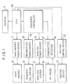
- Fig. 1 is a schematic block diagram of one embodiment of a nuclear magnetic resonance imaging apparatus having a non-invasive temperature distribution measurement function according to the present invention.
- Fig. 2 is an imaging sequence diagram for a phase mapping spin echo sequence also suitable for the chemical shift measurement to be made by the apparatus of Fig. 1.
- Fig. 3 is an imaging sequence diagram for a high speed imaging sequence also suitable for the chemical shift measurement to be made by the apparatus of Fig. 1.
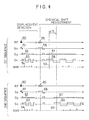
- Fig. 4 is an imaging sequence diagram for an ultra high speed imaging sequence also suitable for the chemical shift measurement to be made by the apparatus of Fig. 1, in a case of detecting the body movement of the target body.
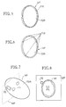
- Fig. 8 is an illustration of an NMR image obtained by using the imaging target view field of Fig. 7 at a measurement plane indicated in Fig. 7.
- Fig. 1 one embodiment of a method and an apparatus for non-invasive measurement of a temperature distribution within a target body using a nuclear magnetic resonance imaging according to the present invention will be described in detail.
- Fig. 1 schematically shows a configuration of a nuclear magnetic resonance imaging apparatus having a non-invasive temperature distribution measurement function.
- the apparatus comprises: a main magnet 10 for generating a static magnetic field in which a target body such as a living body as a measurement target is placed; a main magnet power source 11 for driving the main magnet 10 appropriately; gradient coil system 12 for generating gradient magnetic fields in three mutually orthogonal directions (X, Y, and Z directions) in superposition to the static magnetic field; a gradient coil power source 13 for driving the gradient coil system 12 appropriately; a shim coil system 14 for adjusting the homogeneity of the static magnetic field generated by the main magnet 10; a shim coil power source 15 for driving the shim coil system 14 appropriately; an RF (radio frequency) probe 16 for applying RF pulses to the target body and detecting NMR signals emitted from the target body in response to the application of the RF pulses; a transmitter 17 for supplying appropriate RF pulses to the RF probe 16; a receiver 18 for receiving, amplifying, and collecting the NMR signals detected by the RF probe 16; a sequence controller 19
- the present invention utilizes the known fact that the hydrogen bond strength dependent on the temperature can affect the shielding constant related to the chemical shift, so that the temperature can be determined from the change of the chemical shift for the hydrogen bonded hydroxy radical (-OH).
- the chemical shift for the hydroxy radical (-OH) such as the hydroxy radical (-OH) in the pure water, the hydroxy radical (-OH) with respect to the methyl radical (-CH 3 ) in the methanol (CH 3 OH), and the hydroxy radical (-OH) with respect to the methylene radical (-CH 2 -) in the ethylene glycol (HO-CH 2 -CH 2 -OH)
- the chemical shift for the hydroxy radical (-OH) such as the hydroxy radical (-OH) in the pure water
- the temperature can be calculated from the result of the chemical shift measurement by establishing the relationship between the chemical shift data and the temperatures in advance.
- phase difference ⁇ (x, y, z) at each position (x, y, z) between two NMR images obtained before and after the heating by the heating device 21'with different values for the period ⁇ between the 90° RF pulse 29 and the 180° RF pulse 30 can be expressed by the following expression (8).
- ⁇ (x, y, z) ⁇ B(x, y, z) ⁇
- ⁇ is the gyromagnetic ratio
- ⁇ B(x, y ,z) is a spatial deviation accounting for the inhomogeneity of the static magnetic field ( ⁇ B H ), the chemical shift difference ( ⁇ Bc), and the temperature dependency ( ⁇ B ⁇ ), at each position (x, y, z).
- the phase mapping image of the temperature independent chemical shift components such as CH 2 and CH 3 alone can be obtained by using the appropriate RF pulse sequences for selectively exciting or saturating only these temperature independent chemical shift components prior to the imaging sequence of Fig. 2, such that the temperature distribution image given in the absolute temperature can be calculated from the difference between the phase mapping image for H 2 O and the phase mapping image for these temperature independent chemical shift components, and displayed on the display 9 in the apparatus of Fig. 1.
- any desired dynamic range can be set up by appropriately adjusting the value of ⁇ indicated in Fig. 2 according to the level of the temperature change to be measured, so that the precision in the measurement can be improved.
- this embodiment can utilize the imaging sequence shown in Fig. 3 in which the phase mapping technique is applied to the field echo sequence, as an illustrative example.
- the ⁇ ° RF pulse 36 is applied by the RF probe 16 while the gradient magnetic fields 40 and 41 in the Z and Y directions are generated by the gradient coil system 12, and then the NMR echo signals 37, 38, and 39 are successively detected by the RF probe 16 while the gradient magnetic field 42 in the X direction which is successively switching its polarity is generated by the gradient coil system 12, such that a high speed data collection can be realized by the successive acquisition of the NMR echo signals 37, 38, and 39 in response to the successive switching of the polarity of the gradient magnetic field 42.
- the temperature distribution image of the target body obtained by this embodiment can be utilized for the diagnosis of the diseases such as the circulation malfunction and tumors.
- the RF pulse 50 (60) is applied by the RF probe 16 while the gradient magnetic fields 51 (61), 52 (62), and 53 (63) in the Z, Y, and X directions are generated by the gradient coil system 12 at timings indicated in Fig. 4, and then the NMR echo signals 54 (64) are successively detected by the RF probe 16 while the gradient magnetic field 53 (63) in the X direction which is successively switching its polarity is generated by the gradient coil system 12, such that an ultra high speed data collection can be realized by the successive acquisition of the NMR echo signals 54 (64) in response to the successive switching of the polarity of the gradient magnetic field 53 (63).
- the RF pulse 55 (65) is applied by the RF probe 16 while the gradient magnetic fields 56 (66), 57 (67), and 58 (68) in the Z, Y, and X directions are generated by the gradient coil system 12 at timings indicated in Fig. 4, and then the NMR echo signals 59 (69) are successively detected by the RF probe 16 while the gradient magnetic field 58 (68) in the X direction which is successively switching its polarity is generated by the gradient coil system 12, such that an ultra high speed data collection can be realized by the successive acquisition of the NMR echo signals 59 (69) in response to the successive switching of the polarity of the gradient magnetic field 58 (68).
- the second sequence differs from the first sequence in that the echo time to be used in the chemical shift measurement part is displaced from the first sequence to the second sequence by ⁇ TE as indicated in Fig. 4, so as to obtain two sets of phase mapping images including a first phase mapping image obtained by the first sequence and a second phase mapping image obtained by the second sequence.
- the entire imaging sequence shown in Fig. 4 is executed both before and after the heating.
- the phase difference at each voxel between the first phase mapping image and second phase mapping image is calculated in each execution of the imaging sequence of Fig. 4.
- the difference image is calculated from the calculated phase differences obtained from the execution before the heating and the execution after the heating, and the calculated difference image is displayed on the display 9 in the apparatus of Fig. 1.
- two sets of phase mapping images are used in order to remove the influence of the image shift in the encoding direction in the ultra high speed imaging sequence due to the change of the magnetic field distributions before and after the heating.
- the difference image obtained from the displacement detection part is utilized to detect the phase change due to the body movement of the target body.
- the data can be collected in the displacement detection part from an entire imaging target view field VF which includes the temperature independent region TIR containing the temperature independent chemical shift components, along with the temperature dependent region TDR containing the temperature dependent chemical shift components whose chemical shifts are to be measured in the chemical shift measurement part.
- the data can be collected in the displacement detection part from predetermined number of temperature independent points TIP within the entire imaging target view field VF at which the temperature independent chemical shift components are located, by using a localized excitation technique.
- the use of the temperature independent points TIP will be advantageous in terms of a time required for the displacement detection part.
- the NMR image taken at a measurement plane MP indicated in Fig. 7 appears as shown in Fig. 8 for example.
- the phantom 70 it is preferable for the phantom 70 to have a shape which can cause a large inhomogeneity to the static magnetic field when the target body moves, such that the phase change due to the body movement of the target body can be detected easily.
- the data collected from this execution of the imaging sequence of Fig. 4 are possibly spoiled by the error due to the body movement of the target body, so that the imaging sequence of Fig. 4 may be executed again to obtain new data.
- the data collected from this execution of the imaging sequence of Fig. 4 are not used for obtaining the difference image with respect to the data collected earlier, but used as a reference for the subsequent data to be collected by the subsequent data acquisitions.
- the phase change due to the body movement of the target body is detected from the difference image
- by sequentially displacing the imaging target region by the appropriate adjustment of the gradient magnetic fields it is possible to find the optimum imaging target region in which the phase change in the difference image can be nullified.
- the imaging target region may be displaced sequentially to find the optimum imaging target region in which the phase change in the difference image can be nullified, and the subsequent data acquisitions may be made with respect to this optimum imaging target region.
Landscapes
- Physics & Mathematics (AREA)
- Spectroscopy & Molecular Physics (AREA)
- Optics & Photonics (AREA)
- High Energy & Nuclear Physics (AREA)
- Condensed Matter Physics & Semiconductors (AREA)
- General Physics & Mathematics (AREA)
- Magnetic Resonance Imaging Apparatus (AREA)
- Measuring And Recording Apparatus For Diagnosis (AREA)
Claims (18)
- Eine Vorrichtung zum Messen einer Temperaturverteilung in einem Zielkörper, gekennzeichnet durcheine Kernspinresonanzbildgebungsvorrichtung zum Aufnehmen von chemischen Verschiebungsdaten von dem Zielkörper in jedem Voxel in einem Bildgebungszielbereich an dem Zielkörper in einer Phasenabbildung (x, y, z), mit und ohne eine induzierte Temperaturänderung des Zielkörpers;eine Berechnungsvorrichtung zum Berechnen einer Phasendifferenzabbildung 1 - 0 zwischen den mit der induzierten Temperaturänderung aufgenommenen chemischen Verschiebungsdaten und den ohne die induzierte Temperaturänderung an jedem Voxel aufgenommenen chemischen Verschiebungsdaten, als eine Phasendifferenz an jedem Voxel zwischen der mit und der ohne die induzierte Temperaturänderung aufgenommenen Phasenabbildung (x, y, z);eine Bildaufbauvorrichtung zum Aufbauen eines Temperaturverteilungsbildes in Übereinstimmung mit der durch die Berechnungsvorrichtung berechneten Differenz an jedem Voxel, durch Umwandeln der durch die Berechnungsvorrichtung an jedem Voxel berechneten Phasendifferenz in eine entsprechende Temperatur; undAnzeigevorrichtung zum Anzeigen des durch die Bildaufbauvorrichtung aufgebauten Temperaturverteilungsbildes, wobeidie Kernspinresonanzbildgebungsvorrichtung dazu angeordnet ist, die chemischen Verschiebungsdaten unter Verwendung einer Phasenabbildungssequenz aufzunehmen.
- Die Vorrichtung nach Anspruch 1, wobei die Kernspinresonanzbildgebungsvorrichtung die Phasenabbildung (x, y, z) für mindestens eine temperaturabhängige chemische Verschiebungskomponente in dem Zielkörper nach und vor der Temperaturänderung des Zielkörpers aufnimmt, als die chemischen Verschiebungsdaten mit bzw. ohne der Temperaturänderung.
- Die Vorrichtung nach Anspruch 1, wobei die Kernspinresonanzbildgebungsvorrichtung die Phasenabbildung (x, y, z) für mindestens eine temperaturabhängige chemische Verschiebungskomponente und mindestens eine temperaturunabhängige chemische Verschiebungskomponente in dem Zielkörper aufnimmt, als die chemischen Verschiebungsdaten mit bzw. ohne die Temperaturänderung.
- Die Vorrichtung nach Anspruch 1, wobei die Phasenzuordnungsbildgebungssequenz, verwendet durch die Kernspinresonanzbildgebungsvorrichtung, entweder eine Phasenabbildung-Spinechosequenz oder eine Phasenabbildung-Bildgebungssequenz ist, wobei eine Vielzahl von Kernspinresonanzsignalen von dem Zielkörper aufgenommen werden, in Antwort auf wiederholte Umkehrungen einer Polarität eines magnetischen Gradientenlesefeldes.
- Die Vorrichtung nach Anspruch 1, wobei der Bildgebungszielbereich einen temperaturunabhängigen Abschnitt enthält; und die Vorrichtung weiter umfasst:
eine Verschiebungserfassungsvorrichtung zum Erfassen einer Verschiebung des Zielkörpers zwischen einer Aufnahme der Phasenabbildung 1 mit der induzierten Temperaturänderung und einer Aufnahme der Phasenabbildung 0 ohne die induzierte Temperaturänderung, in Übereinstimmung mit einer Phasenänderung in den Phasenabbildung, aufgenommen von dem temperaturunabhängigen Abschnitt des Bildgebungszielbereichs mit und ohne die Temperaturänderung, wobei die Phasenänderung dadurch die Verschiebung des Zielkörpers darstellt. - Die Vorrichtung nach Anspruch 5, wobei die Kernspinresonanzbildgebungsvorrichtung die Phasenzuordnungsbildgebungssequenz zum Aufnehmen der Phasenabbildung (x, y, z) für den temperaturunabhängigen Abschnitt getrennt von der Phasenzuordnungs-Bildgebungssequenz zum Aufnehmen der Phasenabbildung
(x, y, z) für einen temperaturabhängigen Abschnitt in dem Bildzielbereich ausführt. - Die Vorrichtung nach Anspruch 5, wobei der temperaturunabhängige Abschnitt des Bildgebungszielbereichs durch ein Phantom bereitgestellt wird, das aus temperaturunabhängigen chemischen Verschiebungskomponenten erstellt ist, und das an dem Zielkörper angeordnet ist, und innerhalb des Bildgebungszielbereichs liegt.
- Die Vorrichtung nach Anspruch 5, weiter umfassend:
eine Vorrichtung zum Einstellen der Stärken der magnetischen Gradientenfelder, die durch die Kernspinresonanzbildgebungsvorrichtung verwendet werden, wenn die Verschiebungserfassungsvorrichtung die Verschiebung erfasst, um den Bildgebungszielbereich zu einer Position zu verschieben, in der die durch die Zielbewegung induzierte Phasenänderung zu Null gemacht wird. - Die Vorrichtung nach Anspruch 1, wobei die Kernspinresonanzbildgebungsvorrichtung zwei Sätze von jeder der Phasenabbildung (x, y, z) mit und ohne die Temperaturänderung aufnimmt, unter Verwendung einer Phasenzuordnungsechosequenz mit unterschiedlichen Echozeiten; und wobei die Berechnungsvorrichtung eine erste Phasendifferenz zwischen den zwei Sätzen der mit der Temperaturänderung aufgenommenen Phasenabbildungen nimmt, und eine zweite Phasendifferenz zwischen den zwei Sätzen der ohne die Temperaturänderung aufgenommenen Phasenabbildungen, und eine Differenz zwischen der ersten Phasendifferenz und der zweiten Phasendifferenz als die Differenz zwischen den Phasenabbildungen, aufgenommen mit und ohne die Temperaturänderung in jedem Voxel, berechnet.
- Ein Verfahren zum Messen einer Temperaturverteilung in einem Zielkörper, gekennzeichnet durch(a) Sammeln in einer Phasenabbildung (x, y, z) von chemischen Verschiebungsdaten von dem Zielkörper in jedem Voxel in einem Bildgebungszielbereich an dem Ziel zum Messen der Temperaturverteilung in einem Körper durch eine Kernspinresonanzbildgebungsvorrichtung, mit und ohne eine induzierte Temperaturänderung des Zielkörpers;(b) Berechnen einer Phasendifferenzabbildung 1 - 0 zwischen den im Schritt (a) mit der induzierten Temperaturänderung aufgenommenen chemischen Verschiebungsdaten und den im Schritt (a) ohne die induzierte Temperaturänderung an jedem Voxel aufgenommenen chemischen Verschiebungsdaten, als eine Phasendifferenz an jedem Voxel zwischen der mit und ohne die induzierte Temperaturänderung aufgenommenen Phasenabbildung (x, y, z);(c) Aufbauen eines Temperaturverteilungsbildes in Übereinstimmung mit der für jedes Voxel im Schritt (b) berechneten Differenz, durch Umwandeln der in dem Schritt (b) berechneten Phasendifferenz an jedem Voxel in eine entsprechende Temperatur; und(d) Anzeigen des im Schritt (c) aufgebauten Temperaturverteilungsbildes, wobei(e) die chemischen Verschiebungsdaten durch die Kernspinresonanzbildgebungsvorrichtung unter Verwendung einer Phasenabbildungssequenz aufgenommen werden.
- Ein Verfahren nach Anspruch 10, wobei im Schritt (a) die Kernspinresonanzbildgebungsvorrichtung die Phasenabbildung (x, y, z) für mindestens eine temperaturabhängige chemische Verschiebungskomponente in dem Zielkörper aufnimmt, nach und vor der Temperaturänderung des Zielkörpers, als die chemischen Verschiebungsdaten mit bzw. ohne die Temperaturänderung.
- Das Verfahren nach Anspruch 10, wobei im Schritt (a) die Kernspinresonanzbildgebungsvorrichtung die Phasenabbildung (x, y, z) für mindestens eine temperaturabhängige chemische Verschiebungskomponente und mindestens eine temperaturunabhängige chemische Verschiebungskomponente in dem Zielkörper aufnimmt, als die chemischen Verschiebungsdaten mit bzw. ohne die Temperaturänderung.
- Das Verfahren nach Anspruch 10, wobei im Schritt (a) die durch die Kernspinresonanzbildgebungsvorrichtung verwendete Phasenzuordnungsbildgebungssequenz entweder eine Phasenzuordnungs-Spinechosequenz oder eine phasenzugeordnete Bildgebungssequenz ist, bei der eine Vielzahl von Kernspinresonanzsignalen von dem Zielkörper in Antwort auf wiederholte Umkehrungen einer Polarität eines magnetischen Gradientenlesefeldes aufgenommen werden.
- Verfahren nach Anspruch 10, wobei der Bildgebungszielbereich einen temperaturunabhängigen Abschnitt enthält; und das Verfahren weiter den Schritt umfasst:
(e) Erfassen einer Versetzung des Zielkörpers zwischen einer Aufnahme der Phasenabbildung 1 mit der induzierten Temperaturänderung und einer Aufnahme der Phasenabbildung 0 ohne die induzierte Temperaturänderung, in Übereinstimmung mit einer Phasenänderung in dem von dem temperaturunabhängigen Abschnitt des Bildgebungszielbereichs mit und ohne der induzierten Temperaturänderung aufgenommenen Phasenabbildungen, wobei die Phasenänderung dabei eine Versetzung des Zielkörpers darstellt. - Das Verfahren nach Anspruch 14, wobei im Schritt (a) die Kernspinresonanzbildgebungsvorrichtung die Phasenzuordnungsbildgebungssequenz zum Aufnehmen der Phasenabbildung (x, y, z) für den temperaturunabhängigen Abschnitt getrennt von der Phasenzuordnungsbildgebungssequenz zum Aufnehmen der Phasenabbildung (x, y, z) für einen temperaturabhängigen Abschnitt in dem Bildgebungszielbereich durchführt.
- Verfahren nach Anspruch 14, wobei der temperaturunabhängige Abschnitt in dem Bildgebungszielbereich durch ein Phantom bereitgestellt wird, bestehend aus temperaturunabhängigen chemischen Verschiebungskomponenten, das an dem Zielkörper angebracht ist und innerhalb des Bildgebungszielbereichs angeordnet ist.
- Das Verfahren nach Anspruch 14, weiter den Schritt umfassend:
(f) Einstellen der Stärken der magnetischen Gradientenfelder, verwendet durch die Kernspinresonanzbildgebungsvorrichtung im Schritt (a), wobei die Versetzung im Schritt (e) erfasst wird, um den Bildgebungszielbereich zu einer Position zu verschieben, an der die durch die Zielbewegung induzierte Phasenänderung zu Null gemacht wird. - Das Verfahren nach Anspruch 10, wobei im Schritt (a) die Kernspinresonanzbildgebungsvorrichtung zwei Sätze von jeder Phasenabbildung (x, y, z) mit und ohne die Temperaturänderung aufnimmt, unter Verwendung einer phasenzugeordneten Echosequenz mit unterschiedlichen Echozeiten; und im Schritt (b) eine erste Phasendifferenz zwischen den zwei mit der Temperaturänderung aufgenommenen Sätzen der Phasenabbildung und eine zweite Phasendifferenz zwischen den zwei ohne die Temperaturänderung aufgenommenen Phasenabbildung abgenommen werden, und eine Differenz zwischen der ersten Phasendifferenz und der zweiten Phasendifferenz als die Differenz zwischen den mit und ohne der Temperaturänderung an jedem Voxel aufgenommenen Phasenabbildung berechnet wird.
Applications Claiming Priority (3)
| Application Number | Priority Date | Filing Date | Title |
|---|---|---|---|
| JP55257/92 | 1992-03-13 | ||
| JP05525792A JP3160351B2 (ja) | 1992-03-13 | 1992-03-13 | 磁気共鳴診断装置 |
| JP5525792 | 1992-03-13 |
Publications (2)
| Publication Number | Publication Date |
|---|---|
| EP0560397A1 EP0560397A1 (de) | 1993-09-15 |
| EP0560397B1 true EP0560397B1 (de) | 2001-11-07 |
Family
ID=12993546
Family Applications (1)
| Application Number | Title | Priority Date | Filing Date |
|---|---|---|---|
| EP93104095A Expired - Lifetime EP0560397B1 (de) | 1992-03-13 | 1993-03-12 | Verfahren und Apparat zur nichtinvasiven Messung der Temperaturverteilung innerhalb eines Körpers durch Bildgebung mittels magnetischer Kernresonanz |
Country Status (4)
| Country | Link |
|---|---|
| US (1) | US5378987A (de) |
| EP (1) | EP0560397B1 (de) |
| JP (1) | JP3160351B2 (de) |
| DE (1) | DE69331073T2 (de) |
Cited By (2)
| Publication number | Priority date | Publication date | Assignee | Title |
|---|---|---|---|---|
| US8368401B2 (en) | 2009-11-10 | 2013-02-05 | Insightec Ltd. | Techniques for correcting measurement artifacts in magnetic resonance thermometry |
| US9289154B2 (en) | 2009-08-19 | 2016-03-22 | Insightec Ltd. | Techniques for temperature measurement and corrections in long-term magnetic resonance thermometry |
Families Citing this family (35)
| Publication number | Priority date | Publication date | Assignee | Title |
|---|---|---|---|---|
| DE4326902C1 (de) * | 1993-08-11 | 1994-10-27 | Hennig Juergen | Verfahren der bildgebenden Kernspintomographie zur Erzeugung von RARE-Bildern mit zusätzlicher Präparation der Magnetisierung zur Kontrastvariation |
| US20030195410A1 (en) * | 1995-08-10 | 2003-10-16 | James Winter | Method of treatment using magnetic resonance and apparatus therefor |
| US5711300A (en) * | 1995-08-16 | 1998-01-27 | General Electric Company | Real time in vivo measurement of temperature changes with NMR imaging |
| JP3586047B2 (ja) * | 1995-09-13 | 2004-11-10 | 株式会社東芝 | 磁気共鳴診断装置 |
| WO1999021024A1 (en) * | 1997-10-16 | 1999-04-29 | Koninklijke Philips Electronics N.V. | Method of and device for determining a temperature distribution in an object by means of magnetic resonance |
| US6032068A (en) * | 1998-02-19 | 2000-02-29 | The Board Of Trustees Of The Leland Stanford Junior University | Non-invasive measurement of frozen tissue temperature using MRI signal |
| JPH11225991A (ja) | 1998-02-19 | 1999-08-24 | Toshiba Corp | 体温監視装置及び体温監視方法 |
| JP3998814B2 (ja) * | 1998-06-16 | 2007-10-31 | 株式会社日立メディコ | 磁気共鳴イメージング装置 |
| JP3781166B2 (ja) * | 1999-03-26 | 2006-05-31 | 株式会社日立メディコ | 磁気共鳴イメージング装置および静磁場均一度維持方法 |
| US6377834B1 (en) * | 1999-05-19 | 2002-04-23 | Wisconsin Alumni Research Foundation | Real time in vivo measurement of temperature changes with contrast enhanced NMR imaging |
| US6768917B1 (en) | 1999-10-01 | 2004-07-27 | Koninklijke Philips Electronics N.V. | Magnetic resonance imaging method and system |
| US6270463B1 (en) | 1999-11-23 | 2001-08-07 | Medrad, Inc. | System and method for measuring temperature in a strong electromagnetic field |
| GB0009353D0 (en) | 2000-04-14 | 2000-05-31 | Nycomed Imaging As | Method |
| JP3964110B2 (ja) * | 2000-08-11 | 2007-08-22 | 株式会社日立メディコ | 磁気共鳴イメージング装置 |
| US20020073441A1 (en) | 2000-12-13 | 2002-06-13 | Ross Brian D. | Compositions and methods for detecting proteolytic activity |
| US6559644B2 (en) * | 2001-05-30 | 2003-05-06 | Insightec - Txsonics Ltd. | MRI-based temperature mapping with error compensation |
| EP1399219A2 (de) | 2001-06-26 | 2004-03-24 | Siemens Aktiengesellschaft | Magnetresonanzanlage und verfahren zum betrieb |
| US6522142B1 (en) * | 2001-12-14 | 2003-02-18 | Insightec-Txsonics Ltd. | MRI-guided temperature mapping of tissue undergoing thermal treatment |
| US7542793B2 (en) * | 2002-08-22 | 2009-06-02 | Mayo Foundation For Medical Education And Research | MR-guided breast tumor ablation and temperature imaging system |
| EP2251695B1 (de) | 2003-12-23 | 2013-07-17 | Mount Sinai Hospital Corporation | Mit endometrialer krankheit assoziierte marker |
| US20050206380A1 (en) * | 2004-03-19 | 2005-09-22 | Seeber Derek A | Method and apparatus for temperature-controlled application of radio frequency power in magnetic resonance imaging |
| JP5198859B2 (ja) * | 2004-08-02 | 2013-05-15 | コーニンクレッカ フィリップス エレクトロニクス エヌ ヴィ | 位相マッピングと、位相基準として用いる基準媒体が関係するmri温度測定 |
| US20060064002A1 (en) * | 2004-09-20 | 2006-03-23 | Grist Thomas M | Method for monitoring thermal heating during magnetic resonance imaging |
| US9207299B2 (en) | 2006-02-28 | 2015-12-08 | Kabushiki Kaisha Toshiba | Magnetic resonance imaging system and magnetic resonance imaging apparatus |
| US8073535B2 (en) * | 2006-07-19 | 2011-12-06 | Invention Science Fund 1 | Radiant energy derived temperature(s) |
| CA2618163A1 (en) | 2008-02-07 | 2009-08-07 | K. W. Michael Siu | Head and neck cancer biomarkers |
| US20110046475A1 (en) * | 2009-08-24 | 2011-02-24 | Benny Assif | Techniques for correcting temperature measurement in magnetic resonance thermometry |
| US8843191B2 (en) * | 2009-09-29 | 2014-09-23 | Koninklijke Philips N.V. | Method for measuring and imaging temperature distribution in tissue |
| US8810246B2 (en) * | 2010-01-19 | 2014-08-19 | Insightec Ltd. | Hybrid referenceless and multibaseline PRF-shift magnetic resonance thermometry |
| EP2642310A1 (de) | 2012-03-22 | 2013-09-25 | Koninklijke Philips N.V. | Interpolierte dreidimensionale thermische Dosiseinschätzungen mithilfe der Magnetresonanzabbildung |
| US9977104B2 (en) * | 2012-06-04 | 2018-05-22 | Koninklijke Philips N.V. | Magnetic resonance imaging along energy-delivering device axis |
| EP2958488B1 (de) * | 2013-02-22 | 2017-08-02 | Koninklijke Philips N.V. | Hyperthermie für die diagnostische bildgebung |
| US9971006B2 (en) | 2015-03-25 | 2018-05-15 | Siemens Healthcare Gmbh | Magnetic resonance method and apparatus to generate a residual map as an indicator of signal model consistency |
| US11119169B2 (en) * | 2019-04-10 | 2021-09-14 | New York University | Multi-nuclear absolute MR thermometry |
| WO2023133071A1 (en) * | 2022-01-04 | 2023-07-13 | Promaxo, Inc. | Relaxation-based magnetic resonance thermometry with a low-field single-sided mri scanner |
Family Cites Families (5)
| Publication number | Priority date | Publication date | Assignee | Title |
|---|---|---|---|---|
| DE3219832A1 (de) * | 1982-05-26 | 1983-12-01 | Bruker Medizintechnik Gmbh, 7512 Rheinstetten | Verfahren zur nicht-invasiven ermittlung von messwerten innerhalb eines lebenden koerpers |
| US4558279A (en) * | 1983-03-07 | 1985-12-10 | University Of Cincinnati | Methods for detecting and imaging a temperature of an object by nuclear magnetic resonance |
| JPS6281538A (ja) * | 1985-10-04 | 1987-04-15 | Jeol Ltd | 磁気共鳴を用いた温度分布測定方法 |
| US4914608A (en) * | 1988-08-19 | 1990-04-03 | The United States Of America As Represented By The Department Of Health And Human Services | In-vivo method for determining and imaging temperature of an object/subject from diffusion coefficients obtained by nuclear magnetic resonance |
| JPH0449949A (ja) * | 1990-06-15 | 1992-02-19 | Hitachi Ltd | 磁気共鳴サーモグラフィー方法 |
-
1992
- 1992-03-13 JP JP05525792A patent/JP3160351B2/ja not_active Expired - Fee Related
-
1993
- 1993-03-11 US US08/029,565 patent/US5378987A/en not_active Expired - Lifetime
- 1993-03-12 DE DE69331073T patent/DE69331073T2/de not_active Expired - Fee Related
- 1993-03-12 EP EP93104095A patent/EP0560397B1/de not_active Expired - Lifetime
Cited By (2)
| Publication number | Priority date | Publication date | Assignee | Title |
|---|---|---|---|---|
| US9289154B2 (en) | 2009-08-19 | 2016-03-22 | Insightec Ltd. | Techniques for temperature measurement and corrections in long-term magnetic resonance thermometry |
| US8368401B2 (en) | 2009-11-10 | 2013-02-05 | Insightec Ltd. | Techniques for correcting measurement artifacts in magnetic resonance thermometry |
Also Published As
| Publication number | Publication date |
|---|---|
| DE69331073T2 (de) | 2002-06-20 |
| DE69331073D1 (de) | 2001-12-13 |
| US5378987A (en) | 1995-01-03 |
| JP3160351B2 (ja) | 2001-04-25 |
| JPH05253192A (ja) | 1993-10-05 |
| EP0560397A1 (de) | 1993-09-15 |
Similar Documents
| Publication | Publication Date | Title |
|---|---|---|
| EP0560397B1 (de) | Verfahren und Apparat zur nichtinvasiven Messung der Temperaturverteilung innerhalb eines Körpers durch Bildgebung mittels magnetischer Kernresonanz | |
| US9977106B2 (en) | MR imaging with B1 mapping | |
| US5711300A (en) | Real time in vivo measurement of temperature changes with NMR imaging | |
| US8478380B2 (en) | Magnetic resonance thermometry in the presence of water and fat | |
| US7542793B2 (en) | MR-guided breast tumor ablation and temperature imaging system | |
| US6566878B1 (en) | Magnetic resonance imaging device and method therefor | |
| US9977108B2 (en) | Metal resistant MR imaging reference scan | |
| US6064203A (en) | Method and apparatus for determining or imaging longitudinal spin relaxation time or producing images which substantially reflect longitudinal spin relaxation time contrast | |
| US4901020A (en) | Pulse sequence for operating a nuclear magnetic resonance tomography apparatus for producing images with different T2 contrast | |
| EP2699931B1 (de) | Bewegungsgesteuerte cest-mrt | |
| US10156625B2 (en) | MR imaging with B1 mapping | |
| US10222437B2 (en) | MR imaging with temperature mapping | |
| US6768917B1 (en) | Magnetic resonance imaging method and system | |
| RU2716870C2 (ru) | Система магнитно-резонансных исследований, имеющая зонды для исследования поля | |
| US20120179028A1 (en) | System and method for determining blood-brain barrier permeability to water | |
| US20060064002A1 (en) | Method for monitoring thermal heating during magnetic resonance imaging | |
| JP3964110B2 (ja) | 磁気共鳴イメージング装置 | |
| JP2889871B1 (ja) | 磁気共鳴診断装置 | |
| JP3189982B2 (ja) | 磁気共鳴イメージング装置 | |
| JP4266574B2 (ja) | 磁気共鳴イメージング装置 | |
| JP2006507072A (ja) | 低次磁場中のmriコイル感度の決定 | |
| JPH0880290A (ja) | 磁気共鳴診断装置 | |
| EP3936882A1 (de) | Magnetresonanzbildgebungssystem und verfahren mit frequenzkalibrierung mittels eines signals eines geosatelliten-positionierungssystems | |
| Wirestam et al. | Evaluation of a restricted-volume technique for T1 measurements in the vicinity of object interfaces |
Legal Events
| Date | Code | Title | Description |
|---|---|---|---|
| PUAI | Public reference made under article 153(3) epc to a published international application that has entered the european phase |
Free format text: ORIGINAL CODE: 0009012 |
|
| 17P | Request for examination filed |
Effective date: 19930312 |
|
| AK | Designated contracting states |
Kind code of ref document: A1 Designated state(s): DE FR GB |
|
| 17Q | First examination report despatched |
Effective date: 19960227 |
|
| RIC1 | Information provided on ipc code assigned before grant |
Free format text: 7G 01R 33/48 A, 7G 01K 11/00 B |
|
| GRAG | Despatch of communication of intention to grant |
Free format text: ORIGINAL CODE: EPIDOS AGRA |
|
| GRAG | Despatch of communication of intention to grant |
Free format text: ORIGINAL CODE: EPIDOS AGRA |
|
| GRAH | Despatch of communication of intention to grant a patent |
Free format text: ORIGINAL CODE: EPIDOS IGRA |
|
| GRAH | Despatch of communication of intention to grant a patent |
Free format text: ORIGINAL CODE: EPIDOS IGRA |
|
| GRAA | (expected) grant |
Free format text: ORIGINAL CODE: 0009210 |
|
| AK | Designated contracting states |
Kind code of ref document: B1 Designated state(s): DE FR GB |
|
| PG25 | Lapsed in a contracting state [announced via postgrant information from national office to epo] |
Ref country code: FR Free format text: LAPSE BECAUSE OF FAILURE TO SUBMIT A TRANSLATION OF THE DESCRIPTION OR TO PAY THE FEE WITHIN THE PRESCRIBED TIME-LIMIT Effective date: 20011107 |
|
| REF | Corresponds to: |
Ref document number: 69331073 Country of ref document: DE Date of ref document: 20011213 |
|
| REG | Reference to a national code |
Ref country code: GB Ref legal event code: IF02 |
|
| PGFP | Annual fee paid to national office [announced via postgrant information from national office to epo] |
Ref country code: FR Payment date: 20020312 Year of fee payment: 10 |
|
| EN | Fr: translation not filed | ||
| PLBE | No opposition filed within time limit |
Free format text: ORIGINAL CODE: 0009261 |
|
| 26N | No opposition filed | ||
| PGFP | Annual fee paid to national office [announced via postgrant information from national office to epo] |
Ref country code: GB Payment date: 20080312 Year of fee payment: 16 |
|
| PGFP | Annual fee paid to national office [announced via postgrant information from national office to epo] |
Ref country code: DE Payment date: 20080306 Year of fee payment: 16 |
|
| GBPC | Gb: european patent ceased through non-payment of renewal fee |
Effective date: 20090312 |
|
| PG25 | Lapsed in a contracting state [announced via postgrant information from national office to epo] |
Ref country code: DE Free format text: LAPSE BECAUSE OF NON-PAYMENT OF DUE FEES Effective date: 20091001 |
|
| PG25 | Lapsed in a contracting state [announced via postgrant information from national office to epo] |
Ref country code: GB Free format text: LAPSE BECAUSE OF NON-PAYMENT OF DUE FEES Effective date: 20090312 |