EP0560319A1 - Drehpflug - Google Patents
Drehpflug Download PDFInfo
- Publication number
- EP0560319A1 EP0560319A1 EP93103829A EP93103829A EP0560319A1 EP 0560319 A1 EP0560319 A1 EP 0560319A1 EP 93103829 A EP93103829 A EP 93103829A EP 93103829 A EP93103829 A EP 93103829A EP 0560319 A1 EP0560319 A1 EP 0560319A1
- Authority
- EP
- European Patent Office
- Prior art keywords
- plow
- sleeve
- packer
- pin
- rotary connection
- Prior art date
- Legal status (The legal status is an assumption and is not a legal conclusion. Google has not performed a legal analysis and makes no representation as to the accuracy of the status listed.)
- Granted
Links
Images

Classifications
-
- A—HUMAN NECESSITIES
- A01—AGRICULTURE; FORESTRY; ANIMAL HUSBANDRY; HUNTING; TRAPPING; FISHING
- A01B—SOIL WORKING IN AGRICULTURE OR FORESTRY; PARTS, DETAILS, OR ACCESSORIES OF AGRICULTURAL MACHINES OR IMPLEMENTS, IN GENERAL
- A01B17/00—Ploughs with special additional arrangements, e.g. means for putting manure under the soil, clod-crushers ; Means for breaking the subsoil
- A01B17/004—Clod-crushers
Definitions
- the invention relates to a rotary plow with at least one additional device, for example a packer, a harrow or a seed drill.
- the invention has for its object to avoid the disadvantages occurring in the conventional device combinations.
- the solution to this problem is that the plow and the trailed additional device are coupled to one another via a rotary connection consisting of a sleeve and a pin.
- the invention consists above all in that a turning or reversing plow and a follow-up or additional device are connected to one another via a rotating connection, the axis of rotation of which extends essentially in a horizontal plane and extends essentially parallel to the plowing direction, so that the Turn the plow or turn it, without this also being the case with the additional device.
- the pivot between the plow and the attachment can consist of a sleeve and a pin or pin.
- the pin or pin is rotatable, but axially fixed in the sleeve.
- the free spigot end is rigidly connected to the attachment while the sleeve is rigidly connected to the plow frame.
- the sleeve of the rotary connection can also be rigidly connected to the additional device and, accordingly, the free end of the pin to the plow frame.
- the following or additional device for example a packer and / or a harrow and / or a seed drill, completely follows the plow and accordingly also steers the relevant additional device when the plow is steered or to be led.
- sowing can be achieved directly behind the plow.
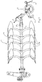
- the rotary plow 1 is connected to a packer 3 via a rotary connection 2.
- the rotary connection consists of a sleeve 2 'and a pin 2' 'which is rotatably and axially displaceably mounted in the sleeve 2' provided with a flat extension 2 '' '.
- the sleeve 2 'of the rotary connection 2 is connected via its flat extension 2' '' to an arm 4, which in turn is connected to the plow frame 5.
- the rear end of the arm 4 is connected to the flat extension 2 ′′ ′′ of the rotary connection 2 via two anchoring bolts 6.
- the free end of the pin 2 '' is connected to the packer frame at 7.
- the packer 3 is connected to a bar 8 and sowing fingers 9.
- the plow 1 is rotated as follows: at the end of a furrow, the plow 1 and the packer 3 are raised and the plow is rotated without turning or turning the packer. As a result of the rotary connection 2, the packer 3 remains in its position during the rotation of the plow 1.
- any pulling device can be used with the plow according to the invention, for example disc packers or combinations of disc packers and sowing fingers and combinations of packers, sowing fingers and seeders with conventional claws.
- the plow 1 is rigidly connected to the rotary connection 2. As a result, rotation is only possible about the longitudinal axis of the pin 2 ′′.
- This has the advantage that the weight of the plow and the effective downward force on the plow bodies are transmitted to the packer 3, which, like other pulling devices, can consequently consist of a lightweight construction.
- the pulling devices for example a packer, a harrow or a seed drill, follow the plow movement completely.
- the pulling tools can also be controlled and steered with the plow.
- the seed is spread directly behind the plow.
- the seeds sometimes reach the area that was previously sown and the sowing width cannot be adjusted to the cutting width, as is the case with the implements integrated according to the invention.
Abstract
Description
- Die Erfindung bezieht sich auf einen Drehpflug mit mindestens einem Zusatzgerät, beispielsweise einem Packer, einer Egge oder einer Sämaschine.
- Es hat sich als großer Vorteil erwiesen, wenn sich die Bodenbearbeitung in der Weise rationalisieren läßt, daß möglichst viele Arbeiten gleichzeitig durchgeführt werden. Hierzu gehören das Pflügen, Verdichten, Eggen und Säen.
- Zwar sind eine Reihe von Kombinationen mit Drehpflügen bekannt; diese bringen jedoch sämtlich bestimmte praktische Probleme mit sich. Darunter ist vor allem die Notwendigkeit zu erwähnen, das Zusatzgerät zusammen mit dem Pflug zu drehen bzw. zu wenden. Das macht es erforderlich, das Zusatzgerät für eine entsprechende Links- und Rechtsbewegung einzurichten. Das ist schwierig und hat zu wenig erfolgreichen Kompromißlösungen geführt.
- Manche Lösungen verwenden gleichzeitig zwei getrennte Systeme, davon eines zum Links- und eines zum Rechtspflügen.
- Die meisten Lösungen erlauben jedoch ein Entkoppeln des Zusatzgeräts am Ende einer Furche und ein erneutes Koppeln nach dem Wenden des Traktors und des Pflugs, bevor die nächsten Furchen gezogen werden.
- Der Erfindung liegt die Aufgabe zugrunde, die bei den herkömmlichen Gerätekombinationen auftretenden Nachteile zu vermeiden.
- Die Lösung dieser Aufgabe besteht darin, daß der Pflug und das nachgezogene Zusatzgerät über eine Drehverbindung aus einer Hülse und einem Zapfen miteinander gekoppelt sind.
- Demgemäß besteht die Erfindung vor allem darin, daß ein Dreh- oder Wendepflug und ein Folge- bzw. Zusatzgerät über eine Drehverbindung miteinander verbunden sind, deren Drehachse im wesentlichen in einer horizontalen Ebene verläuft und sich im wesentlichen parallel zur Pflügerichtung erstreckt, so daß sich der Pflug drehen oder auch wenden läßt, ohne daß dies auch bei dem Zusatzgerät der Fall ist.
- Bei einem aus der deutschen Patentschrift 35 34 129 bekannten Pflug wird auch der Packer stets in derselben Weise aus seiner rechten Arbeitsstellung in seine linke Arbeitsstellung gedreht wie der Pflug selbst. Demzufolge ergibt sich für die Walzen beim Rechtspflügen im Vergleich zum Linkspflügen eine umgekehrte Drehrichtung. Daraus folgt, das weitere, mit dem Packer verbundene Zusatzgeräte unabhängig von der Drehrichtung der Packerwalzen funktionieren müssen.
- Der Drehzapfen zwischen dem Pflug und dem Zusatzgerät kann aus einer Hülse und einem Stift oder Zapfen bestehen. Dabei ist der Stift oder der Zapfen drehbeweglich, jedoch axial fest in der Hülse angeordnet. Das freie Zapfenende ist starr mit dem Zusatzgerät verbunden, während die Hülse starr mit dem Pflugrahmen verbunden ist. Damit ist u.a. der Vorteil verbunden, daß sich das Pfluggewicht und die an den Pflugkörpern wirksame, nach unten gerichtete Kraft auf das Zusatzgerät überträgt, für das somit eine Leichtbaukonstruktion ausreicht.
- Selbstverständlich kann auch die Hülse der Drehverbindung starr mit dem Zusatzgerät und dementsprechend das freie Ende des Zapfens starr mit dem Pflugrahmen verbunden sein.
- Unter den Vorteilen der erfindungsgemäßen Gerätekombination ist besonders zu erwähnen, daß das Folge- bzw. Zusatzgerät, beispielsweise ein Packer und/oder eine Egge und/oder eine Sämaschine, dem Pflug vollständig folgt und demgemäß beim Lenken des Pflugs das betreffende Zusatzgerät ebenfalls gelenkt bzw. geführt wird. Außerdem läßt sich ein Säen direkt hinter dem Pflug erreichen.
- Bei bekannten Systemen wird teilweise noch im Bereich der zuvor gezogenen Furchen gesät und ist es nicht möglich, die Säbreite auf die Schnittbreite des Pflugs einzustellen, wie das bei dem erfindungsgemäßen Pflug der Fall ist. Das erfindungsgemäße System läßt sich auf einfache Weise automatisieren. Bei einem Trecker mit einem automatischen Pflug läßt sich eine Sämaschine sehr gut unter Berücksichtigung des zuvor bereits eingesäten Bereichs einstellen und ergibt sich eine automatische Wegmarkierung.
- Die Erfindung wird nachfolgend anhand eines in der Zeichnung dargestellten Ausführungsbeispiels des näheren erläutert. In der Zeichnung zeigen:
- Fig. 1
- eine Draufsicht auf einen Drehpflug mit einem Nachziehgerät in Gestalt einer Egge; und
- Fig. 2
- die Seitenansicht des Geräts nach Fig. 1 in Kombination mit einem Balken und einem Sägerät.
- Der Drehpflug 1 ist über eine Drehverbindung 2 mit einem Packer 3 verbunden.
- Die Drehverbindung besteht aus einer Hülse 2' und einem Zapfen 2'', der drehbar und axial verschiebefest in der mit einem flachen Ansatz 2''' versehenen Hülse 2' gelagert ist.
- Die Hülse 2' der Drehverbindung 2 ist über ihren flachen Ansatz 2''' mit einem Arm 4 verbunden, der seinerseits in Verbindung mit dem Pflugrahmen 5 steht. Das rückwärtige Ende des Arms 4 ist über zwei Verankerungsbolzen 6 mit dem flachen Ansatz 2''' der Drehverbindung 2 verbunden.
- Das freie Ende des Zapfens 2'' ist bei 7 mit dem Packerrahmen verbunden.
- Bei dem Ausführungsbeispiel nach Fig. 2 ist der Packer 3 mit einem Balken 8 und Säfingern 9 verbunden.
- Bei dem erfindungsgemäßen Kombinationsgerät nach den Fig. 1 und 2 vollzieht sich das Drehen des Pflugs 1 wie folgt: Am Ende einer Furche werden der Pflug 1 und der Packer 3 angehoben und der Pflug ohne ein Drehen oder Wenden des Packers gedreht. Infolge der Drehverbindung 2 verbleibt der Packer 3 während des Drehens des Pflugs 1 in seiner Lage.
- Bei einem erfindungsgemäßen Pflug mit einem Folgegerät ist damit u.a. der Vorteil verbunden, daß alle mit dem Packer 3 verbundenen Geräte wie der Balken 8 und die Säfinger 9 unabhängig davon, ob nun nach rechts oder nach links gepflügt wird, stets ihre Arbeitsrichtung beibehalten. Dies steht im Gegensatz zu bekannten Kombinationsgeräten, bei denen sich eine Umkehr der Arbeitsrichtung ergibt.
- So ergibt sich aus Fig. 2 ohne weiteres, daß der Balken 8 stets vor und die Säfinger 9 stets hinter dem Packer 3 angeordnet sind, unabhängig davon, ob der Pflug 1 nun nach rechts oder nach links pflügt.
- Damit ist der weitere Vorteile verbunden, daß sich mit dem erfindungsgemäßen Pflug jedes Nachziehgerät verwenden läßt, beispielsweise Scheibenpacker oder Kombinationen aus Scheibenpackern und Säfingern sowie Kombinationen aus Packer, Säfingern und Sämaschinen mit üblichen Krallen.
- Wie bereits erwähnt, ist der Pflug 1 starr mit der Drehverbindung 2 verbunden. Demzufolge ist ein Drehen nur um die Längsachse des Zapfens 2'' möglich. Damit ist der Vorteil verbunden, daß das Gewicht des Pfluges und die an den Pflugkörpern wirksame, nach abwärts gerichtete Kraft auf den Packer 3 übertragen wird, der demzufolge ebenso wie andere Nachziehgeräte aus einer Leichtbaukonstruktion bestehen kann.
- Normalerweise wird das Gewicht zur Zugkraftverbesserung auf den Traktor übertragen. Seit einiger Zeit geht jedoch die Entwicklung in Richtung Traktoren mit Vierradantrieb und einer daraus resultierenden größeren Zugkraft, die es erlaubt, die erwähnten Kräfte auf die Nachziehgeräte zu übertragen.
- Die Nachziehgeräte, beispielsweise ein Packer, eine Egge oder eine Sämaschine, folgen vollständig der Pflugbewegung. Demzufolge lassen sich mit dem Pflug gleichzeitig auch die Nachziehgeräte steuern und lenken.
- Bei der erfindungsgemäßen Gerätekombination wird das Saatgut direkt hinter dem Pflug ausgestreut. Hingegen gelangt bei bekannten Geräten das Saatgut teilweise in den zuvor bereits eingesäten Bereich und läßt sich die Säbreite nicht auf die Schnittbreite einstellen, wie das bei den erfindungsgemäß integrierten Geräten der Fall ist.
Claims (3)
- Drehpflug mit mindestens einem nachgezogenen Zusatzgerät, bei dem- der Pflug und das Zusatzgerät über eine Drehverbindung mit sich horizontal in der Pflügerichtung erstreckender Drehachse miteinander verbunden sind und- die Drehverbindung (2) aus einer Hülse (2') und einem Zapfen (2'') besteht.
- Pflug nach Anspruch 1, dadurch gekennzeichnet, daß die Hülse (2') oder der Zapfen (2'') starr mit dem Pflugrahmen (5) oder einem Arm (4) des Pflugrahmens (5) verbunden ist.
- Pflug nach Anspruch 1, dadurch gekennzeichnet, daß die Hülse (2') oder der Zapfen (2'') starr mit dem Zusatzgerät (3) verbunden ist.
Applications Claiming Priority (2)
| Application Number | Priority Date | Filing Date | Title |
|---|---|---|---|
| SE9200744A SE469961B (sv) | 1992-03-10 | 1992-03-10 | Kombinationsjordbruksredskap innefattande växelplog och efterkopplat redskap |
| SE9200744 | 1992-03-10 |
Publications (2)
| Publication Number | Publication Date |
|---|---|
| EP0560319A1 true EP0560319A1 (de) | 1993-09-15 |
| EP0560319B1 EP0560319B1 (de) | 1996-05-22 |
Family
ID=20385583
Family Applications (1)
| Application Number | Title | Priority Date | Filing Date |
|---|---|---|---|
| EP93103829A Expired - Lifetime EP0560319B1 (de) | 1992-03-10 | 1993-03-10 | Drehpflug |
Country Status (9)
| Country | Link |
|---|---|
| EP (1) | EP0560319B1 (de) |
| AT (1) | ATE138241T1 (de) |
| AU (1) | AU3769393A (de) |
| CA (1) | CA2091308A1 (de) |
| DE (1) | DE59302640D1 (de) |
| DK (1) | DK0560319T3 (de) |
| FI (1) | FI931041A (de) |
| SE (1) | SE469961B (de) |
| WO (1) | WO1993017540A1 (de) |
Cited By (2)
| Publication number | Priority date | Publication date | Assignee | Title |
|---|---|---|---|---|
| ITVR20100196A1 (it) * | 2010-10-13 | 2012-04-14 | M G P S R L | Erpice. |
| EP2708102A1 (de) | 2012-09-18 | 2014-03-19 | Kuhn-Huard S.A. | Kombination aus einem landwirtschaftlichen Werkzeug und einem gezogenen Geräts, die hinten an einem Traktor angekuppelt ist |
Families Citing this family (1)
| Publication number | Priority date | Publication date | Assignee | Title |
|---|---|---|---|---|
| GB0119901D0 (en) * | 2001-08-15 | 2001-10-10 | Kverneland Asa | Improvement plough body assembly |
Citations (5)
| Publication number | Priority date | Publication date | Assignee | Title |
|---|---|---|---|---|
| US3476191A (en) * | 1966-08-22 | 1969-11-04 | Charles V Schlabs | Universal hitch for towing tilling implements |
| DE3534129A1 (de) * | 1984-09-28 | 1986-04-10 | C. Van Der Lely N.V., Maasland | Pflug |
| NL8403768A (nl) * | 1984-12-12 | 1986-07-01 | Rumptstad Bv | Inrichting voor het bewerken van de ploegsnede na het ploegen. |
| EP0274299A1 (de) * | 1986-12-02 | 1988-07-13 | Jean-Claude Lechopier | Anhängerkupplung für Drehpflug zur Anbringung von landwirtschäftlichen Zusatzgeräten |
| EP0450436A1 (de) * | 1990-03-24 | 1991-10-09 | Martin Niebler | Bodenbearbeitungsgerät |
Family Cites Families (4)
| Publication number | Priority date | Publication date | Assignee | Title |
|---|---|---|---|---|
| SE336070B (de) * | 1967-03-15 | 1971-06-21 | Oeverums Bruk Ab | |
| FR1560342A (de) * | 1967-12-08 | 1969-03-21 | ||
| DE7730903U1 (de) * | 1977-10-06 | 1978-01-26 | Rabewerk Heinrich Clausing, 4515 Bad Essen | Pflugkoerper |
| US4207952A (en) * | 1978-07-05 | 1980-06-17 | Natta Terry L Van | Plow |
-
1992
- 1992-03-10 SE SE9200744A patent/SE469961B/sv not_active IP Right Cessation
-
1993
- 1993-03-09 FI FI931041A patent/FI931041A/fi not_active Application Discontinuation
- 1993-03-09 WO PCT/NO1993/000036 patent/WO1993017540A1/en active Application Filing
- 1993-03-09 AU AU37693/93A patent/AU3769393A/en not_active Abandoned
- 1993-03-09 CA CA002091308A patent/CA2091308A1/en not_active Abandoned
- 1993-03-10 AT AT93103829T patent/ATE138241T1/de not_active IP Right Cessation
- 1993-03-10 EP EP93103829A patent/EP0560319B1/de not_active Expired - Lifetime
- 1993-03-10 DE DE59302640T patent/DE59302640D1/de not_active Expired - Fee Related
- 1993-03-10 DK DK93103829.3T patent/DK0560319T3/da active
Patent Citations (5)
| Publication number | Priority date | Publication date | Assignee | Title |
|---|---|---|---|---|
| US3476191A (en) * | 1966-08-22 | 1969-11-04 | Charles V Schlabs | Universal hitch for towing tilling implements |
| DE3534129A1 (de) * | 1984-09-28 | 1986-04-10 | C. Van Der Lely N.V., Maasland | Pflug |
| NL8403768A (nl) * | 1984-12-12 | 1986-07-01 | Rumptstad Bv | Inrichting voor het bewerken van de ploegsnede na het ploegen. |
| EP0274299A1 (de) * | 1986-12-02 | 1988-07-13 | Jean-Claude Lechopier | Anhängerkupplung für Drehpflug zur Anbringung von landwirtschäftlichen Zusatzgeräten |
| EP0450436A1 (de) * | 1990-03-24 | 1991-10-09 | Martin Niebler | Bodenbearbeitungsgerät |
Cited By (3)
| Publication number | Priority date | Publication date | Assignee | Title |
|---|---|---|---|---|
| ITVR20100196A1 (it) * | 2010-10-13 | 2012-04-14 | M G P S R L | Erpice. |
| EP2708102A1 (de) | 2012-09-18 | 2014-03-19 | Kuhn-Huard S.A. | Kombination aus einem landwirtschaftlichen Werkzeug und einem gezogenen Geräts, die hinten an einem Traktor angekuppelt ist |
| FR2995498A1 (fr) * | 2012-09-18 | 2014-03-21 | Kuhn Huard Sa | Combinaison d'un instrument agricole et d'un appareil remorque attelee a l'arriere d'un tracteur |
Also Published As
| Publication number | Publication date |
|---|---|
| FI931041A0 (fi) | 1993-03-09 |
| SE9200744D0 (sv) | 1992-03-10 |
| SE469961B (sv) | 1993-10-18 |
| FI931041A (fi) | 1993-09-11 |
| DE59302640D1 (de) | 1996-06-27 |
| SE9200744L (sv) | 1993-09-11 |
| EP0560319B1 (de) | 1996-05-22 |
| CA2091308A1 (en) | 1993-09-11 |
| WO1993017540A1 (en) | 1993-09-16 |
| ATE138241T1 (de) | 1996-06-15 |
| DK0560319T3 (da) | 1996-06-17 |
| AU3769393A (en) | 1993-10-05 |
Similar Documents
| Publication | Publication Date | Title |
|---|---|---|
| EP1080624A1 (de) | Landwirtschaftliches Gerät zum Ausbringen von Gut | |
| DE1900762C3 (de) | Selbsttätig rückstellbare Überlastsicherung für ein landwirtschaftliches Bodenbearbeitungswerkzeug | |
| DE3004576A1 (de) | Kombinatsgeraet zur bodenbearbeitung | |
| DE3105639C2 (de) | ||
| DE1963277A1 (de) | Freigabevorrichtung fuer Bodenbearbeitungsgeraete | |
| AT391050B (de) | Kombinationsgeraet zur landwirtschaftlichen bodenbearbeitung | |
| EP0566821B1 (de) | Aufsattel- oder Anhänge-Drehpflug | |
| EP0560319B1 (de) | Drehpflug | |
| DE3425194A1 (de) | Walzenpflug | |
| DE19954423A1 (de) | Landwirtschaftliche Bestellkombination mit günstiger Schwerpunktsverlagerung | |
| DE3105638A1 (de) | Geraetekombination fuer die landwirtschaft | |
| DE102020133573B3 (de) | Landwirtschaftliches Anbaugerät | |
| DE3327568A1 (de) | Mehrfach-geraetekombination fuer traktoren zur bodenlockerung, saatbettherrichtung und bestellung | |
| DE875097C (de) | Vorrichtung zur Seitensteuerung und Spurhaltung eines Pfluges oder eines aehnlichen parallel einer Kante gleitenden oder rollenden Geraetes | |
| DE19637536C2 (de) | Integrierte Kombination aus einem Pflug und einer Bodenaufbereitungsvorrichtung | |
| DE946670C (de) | Verfahren zur Durchfuehrung der Aufbrecharbeit in Hopfengaerten und Ackergeraet zur Ausuebung des Verfahrens | |
| EP0752202A2 (de) | Tragrahmen für landwirtschaftliche Bodenbearbeitungs- und/oder Bestellkombination | |
| DE2015043A1 (de) | Bodenbearbeitungsgerät, insbeson dere Egge | |
| DE2535268A1 (de) | Tragrahmen fuer landwirtschaftliche maschinen und einrichtungen | |
| EP0556458B1 (de) | Aufsattel- oder Anhänge-Drehpflug | |
| EP0387620B1 (de) | Geschlossene Gerätekombination | |
| DE3838483A1 (de) | Wendepflug | |
| EP0556457B1 (de) | Aufsattel- oder Anhänge-Drehpflug | |
| DE202021101060U1 (de) | Bodenbearbeitungsmaschine | |
| DE1108972B (de) | Vorrichtung zur gleichzeitigen Lenkung von Schlepper und Arbeitsgeraet |
Legal Events
| Date | Code | Title | Description |
|---|---|---|---|
| PUAI | Public reference made under article 153(3) epc to a published international application that has entered the european phase |
Free format text: ORIGINAL CODE: 0009012 |
|
| AK | Designated contracting states |
Kind code of ref document: A1 Designated state(s): AT DE DK FR GB IT NL |
|
| 17P | Request for examination filed |
Effective date: 19931206 |
|
| 17Q | First examination report despatched |
Effective date: 19941013 |
|
| GRAH | Despatch of communication of intention to grant a patent |
Free format text: ORIGINAL CODE: EPIDOS IGRA |
|
| GRAA | (expected) grant |
Free format text: ORIGINAL CODE: 0009210 |
|
| STAA | Information on the status of an ep patent application or granted ep patent |
Free format text: STATUS: THE PATENT HAS BEEN GRANTED |
|
| AK | Designated contracting states |
Kind code of ref document: B1 Designated state(s): AT DE DK FR GB IT NL |
|
| REF | Corresponds to: |
Ref document number: 138241 Country of ref document: AT Date of ref document: 19960615 Kind code of ref document: T |
|
| REG | Reference to a national code |
Ref country code: DK Ref legal event code: T3 |
|
| REF | Corresponds to: |
Ref document number: 59302640 Country of ref document: DE Date of ref document: 19960627 |
|
| GBT | Gb: translation of ep patent filed (gb section 77(6)(a)/1977) |
Effective date: 19960606 |
|
| ITF | It: translation for a ep patent filed |
Owner name: SOCIETA' ITALIANA BREVETTI S.P.A. |
|
| ET | Fr: translation filed | ||
| PLBQ | Unpublished change to opponent data |
Free format text: ORIGINAL CODE: EPIDOS OPPO |
|
| PLBI | Opposition filed |
Free format text: ORIGINAL CODE: 0009260 |
|
| PLBF | Reply of patent proprietor to notice(s) of opposition |
Free format text: ORIGINAL CODE: EPIDOS OBSO |
|
| 26 | Opposition filed |
Opponent name: DAL-BO A/S Effective date: 19970219 |
|
| NLR1 | Nl: opposition has been filed with the epo |
Opponent name: DAL-BO A/S |
|
| PLBF | Reply of patent proprietor to notice(s) of opposition |
Free format text: ORIGINAL CODE: EPIDOS OBSO |
|
| PGFP | Annual fee paid to national office [announced via postgrant information from national office to epo] |
Ref country code: GB Payment date: 20000309 Year of fee payment: 8 |
|
| PGFP | Annual fee paid to national office [announced via postgrant information from national office to epo] |
Ref country code: DK Payment date: 20000327 Year of fee payment: 8 |
|
| PGFP | Annual fee paid to national office [announced via postgrant information from national office to epo] |
Ref country code: NL Payment date: 20000329 Year of fee payment: 8 |
|
| PGFP | Annual fee paid to national office [announced via postgrant information from national office to epo] |
Ref country code: DE Payment date: 20000523 Year of fee payment: 8 |
|
| PGFP | Annual fee paid to national office [announced via postgrant information from national office to epo] |
Ref country code: AT Payment date: 20010112 Year of fee payment: 9 |
|
| PGFP | Annual fee paid to national office [announced via postgrant information from national office to epo] |
Ref country code: FR Payment date: 20010118 Year of fee payment: 9 |
|
| PG25 | Lapsed in a contracting state [announced via postgrant information from national office to epo] |
Ref country code: GB Free format text: LAPSE BECAUSE OF NON-PAYMENT OF DUE FEES Effective date: 20010310 Ref country code: DK Free format text: LAPSE BECAUSE OF NON-PAYMENT OF DUE FEES Effective date: 20010310 |
|
| PG25 | Lapsed in a contracting state [announced via postgrant information from national office to epo] |
Ref country code: NL Free format text: LAPSE BECAUSE OF NON-PAYMENT OF DUE FEES Effective date: 20011001 |
|
| GBPC | Gb: european patent ceased through non-payment of renewal fee |
Effective date: 20010310 |
|
| REG | Reference to a national code |
Ref country code: DK Ref legal event code: EBP |
|
| NLV4 | Nl: lapsed or anulled due to non-payment of the annual fee |
Effective date: 20011001 |
|
| PG25 | Lapsed in a contracting state [announced via postgrant information from national office to epo] |
Ref country code: DE Free format text: LAPSE BECAUSE OF NON-PAYMENT OF DUE FEES Effective date: 20020101 |
|
| PG25 | Lapsed in a contracting state [announced via postgrant information from national office to epo] |
Ref country code: AT Free format text: LAPSE BECAUSE OF NON-PAYMENT OF DUE FEES Effective date: 20020310 |
|
| PG25 | Lapsed in a contracting state [announced via postgrant information from national office to epo] |
Ref country code: FR Free format text: LAPSE BECAUSE OF NON-PAYMENT OF DUE FEES Effective date: 20021129 |
|
| REG | Reference to a national code |
Ref country code: FR Ref legal event code: ST |
|
| PG25 | Lapsed in a contracting state [announced via postgrant information from national office to epo] |
Ref country code: IT Free format text: LAPSE BECAUSE OF NON-PAYMENT OF DUE FEES Effective date: 20050310 |