EP0559654B1 - Processus de freinage sans blocage des roues d'un vehicule - Google Patents
Processus de freinage sans blocage des roues d'un vehicule Download PDFInfo
- Publication number
- EP0559654B1 EP0559654B1 EP91916978A EP91916978A EP0559654B1 EP 0559654 B1 EP0559654 B1 EP 0559654B1 EP 91916978 A EP91916978 A EP 91916978A EP 91916978 A EP91916978 A EP 91916978A EP 0559654 B1 EP0559654 B1 EP 0559654B1
- Authority
- EP
- European Patent Office
- Prior art keywords
- time
- period
- threshold value
- wheel
- time period
- Prior art date
- Legal status (The legal status is an assumption and is not a legal conclusion. Google has not performed a legal analysis and makes no representation as to the accuracy of the status listed.)
- Expired - Lifetime
Links
Images

Classifications
-
- B—PERFORMING OPERATIONS; TRANSPORTING
- B60—VEHICLES IN GENERAL
- B60T—VEHICLE BRAKE CONTROL SYSTEMS OR PARTS THEREOF; BRAKE CONTROL SYSTEMS OR PARTS THEREOF, IN GENERAL; ARRANGEMENT OF BRAKING ELEMENTS ON VEHICLES IN GENERAL; PORTABLE DEVICES FOR PREVENTING UNWANTED MOVEMENT OF VEHICLES; VEHICLE MODIFICATIONS TO FACILITATE COOLING OF BRAKES
- B60T8/00—Arrangements for adjusting wheel-braking force to meet varying vehicular or ground-surface conditions, e.g. limiting or varying distribution of braking force
- B60T8/32—Arrangements for adjusting wheel-braking force to meet varying vehicular or ground-surface conditions, e.g. limiting or varying distribution of braking force responsive to a speed condition, e.g. acceleration or deceleration
- B60T8/58—Arrangements for adjusting wheel-braking force to meet varying vehicular or ground-surface conditions, e.g. limiting or varying distribution of braking force responsive to a speed condition, e.g. acceleration or deceleration responsive to speed and another condition or to plural speed conditions
-
- B—PERFORMING OPERATIONS; TRANSPORTING
- B60—VEHICLES IN GENERAL
- B60T—VEHICLE BRAKE CONTROL SYSTEMS OR PARTS THEREOF; BRAKE CONTROL SYSTEMS OR PARTS THEREOF, IN GENERAL; ARRANGEMENT OF BRAKING ELEMENTS ON VEHICLES IN GENERAL; PORTABLE DEVICES FOR PREVENTING UNWANTED MOVEMENT OF VEHICLES; VEHICLE MODIFICATIONS TO FACILITATE COOLING OF BRAKES
- B60T8/00—Arrangements for adjusting wheel-braking force to meet varying vehicular or ground-surface conditions, e.g. limiting or varying distribution of braking force
- B60T8/17—Using electrical or electronic regulation means to control braking
- B60T8/173—Eliminating or reducing the effect of unwanted signals, e.g. due to vibrations or electrical noise
Definitions
- the invention relates to a method for the anti-lock braking of the wheels of a vehicle, in which brake pressure is built up or down or kept constant as a function of the slip and / or the change in rotational speed (positive or negative deceleration) of a braked wheel in relation to at least one threshold value, and during which the respective re-accelerations of the braked wheels are measured during successive control cycles of the anti-lock braking in order to vary the threshold value to suppress undesirable control processes that can be triggered, in particular, by vibrations of the axle of the vehicle, or to prevent a reduction in brake pressure for a predetermined period of time.
- the rotation of the individual wheels of the vehicle is continuously monitored, and in particular the slipping of the braked wheels and their deceleration are determined in order to determine a tendency of the wheel to lock and to prevent locking.
- the wheel slip or the deceleration indicate a tendency to lock, which is determined by the fact that certain predetermined threshold values with regard to slip and / or deceleration are exceeded, a further increase in the pressure in the brake of the wheel concerned is ended or the brake pressure is reduced.
- the anti-lock braking system should react as sensitively and without delay to changes in the turning behavior of the braked wheel that indicate a tendency to lock.
- a sensitive setting of the threshold values stands in the way of the fact that under certain, not unlikely conditions, braked wheels can show a turning behavior which indicates a strong deceleration, even though the wheel is still running in a good braking condition. This phenomenon is well known and is described in detail, for example, in DE-OS 33 45 729. Axle vibrations, in particular, can cause relatively large differences between the vehicle speed and the wheel speed, which simulate unstable running of the wheel and therefore undesirable control processes, i.e. can trigger an undesirable reduction in brake pressure. Even if the braked wheel drives into a pothole or on an irregular road, a jerky spin acceleration followed by a strong deceleration can occur.
- Such axis vibrations or the like can therefore lead to narrow threshold values with respect to the Deceleration of the wheel are exceeded and an undesirable control process (pressure reduction on the braked wheel) is initiated, although the wheel is not at risk of locking.
- the threshold value which is decisive for initiating the control is varied as a function of the acceleration of acceleration of the controlled wheel.
- the acceleration of acceleration of the braked wheel i.e. the restart of the wheel after a deceleration
- the threshold value is varied as a function of the degree of acceleration.
- the threshold value is therefore currently increased to the value resulting from the acceleration, and then decays to the basic value in a predetermined time function (exponential or linear).
- the basic threshold is the threshold that the system normally takes, i.e. then when the acceleration of acceleration of the wheel is below the above-mentioned limit value or no regulation is carried out.
- the present invention is based on a further analysis of the phenomenon of the axle vibrations and proposes an ABS control algorithm which ensures that undesired ABS controls caused by axle vibrations are reliably switched off.
- axles of a motor vehicle form with all other components connected to them elastically or rigidly an oscillatory system (spring-mass system) which, when deflected from the rest position, can carry out vibrations with considerable amplitudes.
- spring-mass system oscillatory system
- the suspension strut (e.g. of the McPherson type) of the front axle is only guided in the longitudinal direction via a stabilizer (spring bar), which is held in rubber bearings.
- ABS braking pressure is reduced and the braking torque is reduced, the vehicle axle is accelerated in the direction of travel.
- the preloaded system consisting of the axle and associated parts now releases itself from the extreme position described and swings forward over the so-called zero position (which corresponds to the idle state of the axle).
- the invention has for its object to make the occurrence of axle vibrations reliably detectable in an anti-lock vehicle brake system, so that impairment of the ABS control by axle vibrations can be avoided.
- the resonance oscillation frequencies are between 7 and 15 Hz depending on the vehicle type.
- this resonance frequency can be determined experimentally, e.g. by deflection from the rest position and measurement of the period of oscillation.
- the present invention is based on the knowledge that a precise observation of the deceleration of a previously strongly re-accelerated wheel can provide information about possible axle vibrations.
- the wheel re-acceleration is observed for each control cycle in the course of an ABS control consisting of several control cycles.
- a particularly high re-acceleration a re-acceleration above the predetermined limit value
- the re-acceleration has also taken place relatively quickly, (unlike in the prior art, where Axial vibration is deduced directly from the re-acceleration)
- a further measurement is carried out, specifically with regard to the wheel rotation deceleration in the control cycle immediately following the strong re-acceleration.
- the invention is therefore based on the knowledge that, for a given vehicle, the deceleration of a braked wheel with an axle vibration has a typical oscillating course, in which the oscillation periods are characteristic of the given vehicle axle, that is to say are dependent on the vehicle-specific resonance vibration of the axle.
- the further course of the wheel deceleration is monitored and then, if within a relatively short predetermined time period, which is, for example, somewhat larger than the vehicle-specific resonance oscillation period of the axle , again a rapid decrease in vehicle deceleration and a subsequent relatively rapid increase in vehicle deceleration occur to which The presence of an axle vibration is closed and an unwanted reduction in brake pressure on the braked wheel triggered by this axle vibration is prevented.
- This prevention of triggering undesired control processes can e.g. can be achieved by changing the threshold value which is decisive for the initiation of a pressure reduction in the direction of a less sensitive response behavior of the ABS control, or by simply for a predetermined period of time which is longer than a resonant oscillation period of the axis, but shorter than the typical period a control cycle, the reduction of brake pressure is excluded.
- a time value assigned to the resonance vibration of the axle is determined for the given vehicle.
- This time value corresponds to an oscillation period in the event of resonance and can be determined experimentally for any given vehicle type.
- This time value is saved for the given vehicle type in the computer of the ABS system and saved for all time and is available for all ABS regulations.
- the time period is measured in which the wheel rotation deceleration is below a predetermined limit value, i.e. the time period that lies between the time is determined in which the wheel rotation deceleration falls below the limit value and the time at which the wheel rotation deceleration exceeds this limit value again.
- the invention is based on the knowledge that this time period provides information about whether the vehicle axle is in a vibration state which complicates the ABS control.
- the time period measured as described above is therefore compared with the stored time value, which corresponds to half the resonance oscillation period of the axis, in order to infer an axle oscillation condition if they match within a predetermined tolerance.
- Is such an axis vibration condition on this Detected in this way it can be rendered harmless for ABS control in a variety of ways, for example by making the threshold value less sensitive, for a period of time that is at least somewhat longer than a resonance oscillation period of the axis.
- it can also be provided for a predetermined period of time that the ABS computer does not bring about a reduction in the brake pressure, even if the threshold value is exceeded in this period, which would otherwise result in a pressure decrease.
- ABS control algorithm described above is implemented using modern technology in that a processor is programmed in accordance with the algorithm. All hardware components required for realizing the invention, such as processors, valves, control means etc., are generally known in ABS technology.
- a threshold value that is decisive for initiating a pressure reduction can be, for example, a slip, deceleration or speed threshold value.
- a delay threshold value is used as an example in the description of an exemplary embodiment.
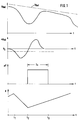
- Fig. 1 (from top to bottom) over a common time scale (time t) the rotational speed v wheel of a braked wheel including the so-called reference speed v Ref , the associated deceleration of the braked wheel (i.e. the first derivative of the one shown in the upper figure) Rotational speed over time) a wheel including a comparison value V S with respect to the deceleration, a change ⁇ V of the comparison value and the associated brake pressure p.
- the course of the wheel speed v wheel in Fig. 1 (top) shows that no axle vibrations occur.
- the wheel speed is greatly reduced due to braking, so that the deceleration a wheel at time t 1 falls below the comparison value V S and due to the reduction in brake pressure p, the wheel speed v wheel then "recovers" and the deceleration becomes an acceleration, and exceeds the comparison value V S at time t2 again. This recovery of the wheel has the result that the brake pressure p is increased again from the time t2.
- the effective threshold value is also increased, ie to the initially set comparison value V S , an additional amount .DELTA.V is added from time t.sub.2, which results in less sensitive ABS control.
- the "normal" comparison value V S is increased by an additional amount ⁇ V as shown in FIG. 1, so that the effective threshold is significantly increased for the time period T x in which the increased value ⁇ V is effective is and therefore exceeding this threshold is significantly less likely and pressure reduction at least for the time period T x is generally excluded.
- the increase in the comparison value V S by the additional amount ⁇ V to achieve an effective threshold value V S + ⁇ V is only carried out if the re-acceleration a wheel of the braked wheel takes place relatively quickly, that is to say in a relatively short period of time after the time t 1. So it is determined whether the re-acceleration of the wheel over a predetermined comparison value and whether the period between the times t1 and t2 is so short that this indicates the possibility of the presence of an axis vibration. That means that the time period from t 1 - t 2 is then approximately in the range of half an oscillation period of a resonant axis oscillation. Tolerances, ie deviations from the vehicle-specific resonant axle oscillation period, are permitted.
- the ABS control algorithm therefore assumes that there is a certain probability that the axis of the braked wheel is in an oscillation state. So that after the time t2 the axle vibration does not cause an undesirable reduction in brake pressure p (see FIG. 1, lower image), the effective threshold value is set to the amount V S + ⁇ V at time t2 and for a period of time T x ( 1), which is initially somewhat larger than a typical resonant oscillation period of the axis (cf. also FIG. 2). In the case shown in Fig.
- Fig. 2 shows an illustration in which there is an axis vibration.
- the processes up to time t z are as described above with reference to FIG. 1.
- Between the times t1 and t2 has therefore a rapid (that is to say occurring within a relatively short time interval) re-acceleration of the wheel, which was also above a relatively high extreme value, so that the effective threshold value is increased by the amount ⁇ V at time t2.
- This raising of the threshold value takes place again for the time period T x .
- the wheel deceleration a wheel falls below the comparison value V s again , which the ABS computer evaluates as a strong indicator that a Axis vibration is present.
- the time period T y is then measured in which the wheel deceleration a Rad is below the comparison value V S (cf. FIG. 2). This is the time span between the times t4 and t5.
- the ABS computer extends, after the point in time t5, the period in which the effective threshold value is increased by an additional amount ⁇ V by a further period T z , the period T z being dependent on that previously measured period of time between the times t4 and t5, ie the period of time T y .
- the set time period T z is somewhat longer than the measured time period T y .
- an axis vibration will occur as a damped vibration, as is also assumed in FIG. 2. This means that the amplitudes of the time course of the wheel deceleration a wheel decrease. Accordingly, following an initial increase in the effective threshold value by the amount ⁇ V at the time t2 each time the comparison value V S falls below at the times t4, t6 etc., the amount of the increase ⁇ V in the threshold value can be reduced, as in FIG is shown.
- the axis of the braked wheel also swings beyond the time t5 even further, but with a dampened amplitude.
- the wheel deceleration a wheel in turn falls below the comparison value V S within the time period T z , which serves as an indication to the ABS computer that the axle vibration continues.
- the time period T ' y is then measured accordingly, ie the time period between the times triosen and t7.
- the ABS computer therefore does not set the effective threshold value V S + ⁇ V to the “normal value” (ie V S ), but instead allows an increase in the effective threshold value to be effective, specifically for a period of time T ′ z , which is also set here approximately equal to half an oscillation period of a resonance oscillation of the axis. Only after the point in time t7 does the oscillating axis settle sufficiently again, so that there is no shortfall in the comparison value V S within the period T ′ z , which is why the increase in the threshold value stops at point in time t8.
- the increase ⁇ V in the threshold value is a step function in Depends on the time shown.
Landscapes
- Engineering & Computer Science (AREA)
- Transportation (AREA)
- Mechanical Engineering (AREA)
- Regulating Braking Force (AREA)
Abstract
Claims (1)
- Procédé de freinage anti-blocage des roues d'un véhicule, selon lequel :a) le comportement dynamique de la roue est mesuré, et on en déduit un patinage ou des modifications de la vitesse de rotation;b) les signaux ainsi obtenus en cas de dépassement de valeurs de seuil associées, servent à abaisser, à maintenir constante ou à faire remonter la pression de freinage;c) pendant des cycles de régulation successifs de la protection anti-blocage, chacune des réaccélérations correspondantes des roues est mesurée;d) au début de la remontée de la pression de freinage, la valeur de seuil prise pour base est portée à un niveau plus élevé, pour empêcher le déclenchement d'opérations de régulation indésirables, du fait d'oscillations de l'essieu, ou pour interdire un abaissement de la pression de freinage pour un espace de temps prédéfini;e) la valeur de seuil qui a été portée à un niveau plus élevé à l'intérieur du cycle de régulation, est ramenée à la valeur de seuil prise de base,caractérisé en ce quef1) la valeur de seuil portée à un niveau plus élevé (VS + ΔV) y est maintenue pour un espace de temps prédéfini (Tx), puis est ensuite ramenée à sa valeur de base (VS) si, pendant l'espace de temps prédéfini (Tx), on n'a mesuré aucune décélération (aRoue) de la roue, qui soit inférieure à une valeur de comparaison (VS), par rapport à la décélération, étant entendu que l'espace de temps prédéfini (Tx) est un peu plus grand qu'une période d'oscillation de l'essieu de roue,f2)a) ensuite, quand la décélération (aRoue) de la roue, à l'intérieur de l'espace de temps prédéfini (Tx), redevient inférieure à la valeur de comparaison (VS), cette chute n'entraîne aucun abaissement de la pression de freinage, etb) un espace de temps (Ty) est mesuré, pendant lequel la décélération (aRoue) de la roue freinée est inférieure à la valeur de comparaison (VS), etf3) ensuite, si cet espace de temps (Ty) est plus court qu'un espace de temps (Tymax) prédéfini, un abaissement de la pression de freinage est de nouveau interdit pour un espace de temps supplémentaire (Ty + Tz), qui est au moins aussi long qu'une période d'oscillation de l'essieu de roue.
Applications Claiming Priority (3)
| Application Number | Priority Date | Filing Date | Title |
|---|---|---|---|
| DE4028193A DE4028193C1 (fr) | 1990-09-05 | 1990-09-05 | |
| PCT/EP1991/001812 WO1993005990A1 (fr) | 1990-09-05 | 1991-09-23 | Processus de freinage sans blocage des roues d'un vehicule |
| US08/039,439 US5342118A (en) | 1990-09-05 | 1993-04-30 | Anti-lock braking method to retard the wheels of a vehicle |
Publications (2)
| Publication Number | Publication Date |
|---|---|
| EP0559654A1 EP0559654A1 (fr) | 1993-09-15 |
| EP0559654B1 true EP0559654B1 (fr) | 1995-09-13 |
Family
ID=25896605
Family Applications (1)
| Application Number | Title | Priority Date | Filing Date |
|---|---|---|---|
| EP91916978A Expired - Lifetime EP0559654B1 (fr) | 1990-09-05 | 1991-09-23 | Processus de freinage sans blocage des roues d'un vehicule |
Country Status (6)
| Country | Link |
|---|---|
| US (1) | US5342118A (fr) |
| EP (1) | EP0559654B1 (fr) |
| JP (1) | JP3045768B2 (fr) |
| KR (1) | KR100193391B1 (fr) |
| DE (1) | DE4028193C1 (fr) |
| WO (1) | WO1993005990A1 (fr) |
Families Citing this family (12)
| Publication number | Priority date | Publication date | Assignee | Title |
|---|---|---|---|---|
| DE4028193C1 (fr) * | 1990-09-05 | 1992-02-27 | Lucas Industries P.L.C., Birmingham, West Midlands, Gb | |
| DE4032506A1 (de) * | 1990-10-12 | 1992-04-16 | Lucas Ind Plc | Verfahren zum regeln des bremsdruckes in einer blockiergeschuetzten fahrzeugbremsanlage |
| KR960702392A (ko) * | 1994-03-25 | 1996-04-27 | 지 에이 애넷 | 차량용 앤티-록 브레이크 시스템 |
| US5615935A (en) * | 1995-09-21 | 1997-04-01 | Robert Bosch Gmbh | ABS control for a four wheel drive vehicle experiencing axle oscillations |
| DE19538545A1 (de) * | 1995-10-17 | 1997-04-24 | Teves Gmbh Alfred | Verfahren zur Verbesserung des Regelverhaltens einer Bremsanlage |
| DE19601529A1 (de) * | 1996-01-17 | 1997-07-24 | Teves Gmbh Alfred | Verfahren zur Verbesserung des Regelverhaltens eines ABS in einer Off-Road-Fahrsituation |
| DE19705948A1 (de) * | 1997-02-17 | 1998-08-20 | Itt Mfg Enterprises Inc | Verfahren zum Dämpfen von Antriebsstrangschwingungen |
| US5958322A (en) | 1998-03-24 | 1999-09-28 | 3M Innovation Properties Company | Method for making dimensionally stable nonwoven fibrous webs |
| DE102008003874A1 (de) * | 2008-01-08 | 2009-07-23 | Siemens Aktiengesellschaft | Verfahren zum Bereitstellen von Eingangssignalen einer Regelungseinheit zum Regeln einer in Räder eines Fahrzeugs eingeleiteten Kraft |
| KR101417856B1 (ko) * | 2010-11-16 | 2014-07-09 | 주식회사 만도 | 가변 임계값을 이용한 휠 압력제어 방법 |
| DE102014212984A1 (de) | 2014-07-03 | 2016-01-07 | Continental Teves Ag & Co. Ohg | Verfahren zur Vermeidung von Fehlanregelungen eines Schlupfregelsystems eines Bremssystems eines Fahrzeugs |
| KR102545487B1 (ko) | 2018-11-15 | 2023-06-21 | 한국전력공사 | 지하 구조물용 안전장치 |
Citations (1)
| Publication number | Priority date | Publication date | Assignee | Title |
|---|---|---|---|---|
| DE3345729A1 (de) * | 1983-12-17 | 1985-06-27 | Alfred Teves Gmbh, 6000 Frankfurt | Verfahren und schaltungsanordnung zur unterdrueckung unerwuenschter regelvorgaenge in schlupfgeregelten bremsanlagen |
Family Cites Families (5)
| Publication number | Priority date | Publication date | Assignee | Title |
|---|---|---|---|---|
| US4140353A (en) * | 1968-09-20 | 1979-02-20 | Kelsey-Hayes Company | Skid control system |
| DE3805270A1 (de) * | 1988-02-19 | 1989-08-31 | Lucas Ind Plc | Verfahren zum regeln des bremsdruckes in einer blockiergeschuetzten fahrzeugbremsanlage |
| EP0363515B1 (fr) * | 1988-10-13 | 1993-01-20 | Siemens Aktiengesellschaft | Procédé pour distinguer le glissement des roues de véhicules des vibrations de la chaîne de transmission |
| GB2227534B (en) * | 1988-11-17 | 1993-07-21 | Tokico Ltd | Anti-skid brake control apparatus |
| DE4028193C1 (fr) * | 1990-09-05 | 1992-02-27 | Lucas Industries P.L.C., Birmingham, West Midlands, Gb |
-
1990
- 1990-09-05 DE DE4028193A patent/DE4028193C1/de not_active Expired - Lifetime
-
1991
- 1991-09-23 JP JP03515740A patent/JP3045768B2/ja not_active Expired - Fee Related
- 1991-09-23 EP EP91916978A patent/EP0559654B1/fr not_active Expired - Lifetime
- 1991-09-23 KR KR1019930701528A patent/KR100193391B1/ko not_active IP Right Cessation
- 1991-09-23 WO PCT/EP1991/001812 patent/WO1993005990A1/fr active IP Right Grant
-
1993
- 1993-04-30 US US08/039,439 patent/US5342118A/en not_active Expired - Lifetime
Patent Citations (1)
| Publication number | Priority date | Publication date | Assignee | Title |
|---|---|---|---|---|
| DE3345729A1 (de) * | 1983-12-17 | 1985-06-27 | Alfred Teves Gmbh, 6000 Frankfurt | Verfahren und schaltungsanordnung zur unterdrueckung unerwuenschter regelvorgaenge in schlupfgeregelten bremsanlagen |
Also Published As
| Publication number | Publication date |
|---|---|
| WO1993005990A1 (fr) | 1993-04-01 |
| JP3045768B2 (ja) | 2000-05-29 |
| DE4028193C1 (fr) | 1992-02-27 |
| KR100193391B1 (ko) | 1999-06-15 |
| US5342118A (en) | 1994-08-30 |
| EP0559654A1 (fr) | 1993-09-15 |
| JPH06502365A (ja) | 1994-03-17 |
| KR930702185A (ko) | 1993-09-08 |
Similar Documents
| Publication | Publication Date | Title |
|---|---|---|
| EP0559654B1 (fr) | Processus de freinage sans blocage des roues d'un vehicule | |
| EP0733530B1 (fr) | Système de commande ABS et/ou ASC pour véhicules | |
| EP0329071B1 (fr) | Procédé de commande de pression de frein dans un système de freins anti-verrouillage d'un véhicule | |
| DE2146825C2 (de) | Antiblockier-Regelanordnung für druckmittelbetätigte Fahrzeugbremsen | |
| EP0550849B1 (fr) | Procédé pour contrÔler la force de freinage de motocyclettes | |
| EP0960752A2 (fr) | Procédé et dispositif pour déterminer des grandeurs d'oscillation et d'autres grandeurs spécifiques d'un véhicule roulant et utilisation de ces valeurs | |
| EP0583252B1 (fr) | Montage pour un systeme de freinage pourvu d'une regulation electronique du dispositif d'antiblocage | |
| DE4032506C2 (fr) | ||
| DE2726738C2 (de) | Schaltungsanordnung zur Regelung des Bremsdruckes in blockiergeschützten Fahrzeugbremsanlagen | |
| DE3836680A1 (de) | Schaltungsanordnung fuer ein fahrzeug mit antriebsschlupfregelung | |
| DE3806213C2 (fr) | ||
| EP0451240B1 (fr) | Procede de reglage de la pression de freinage d'un systeme de freinage de vehicules a anti-bloqueur | |
| EP0776288B1 (fr) | Procede de reconnaissance rapide de roues de secours | |
| WO1990006869A1 (fr) | Systeme de reglage d'antiblocage des freins | |
| EP0960042B1 (fr) | Procede pour identifier et amortir les vibrations d'une chaine cinematique | |
| DE102004053695B4 (de) | Verfahren zur Dämpfung von Karosserie- und Fahrwerks oder Radschwingungen eines Kraftfahrzeuges | |
| DE4320904C2 (de) | Antiblockierregelsystem | |
| DE19705948A1 (de) | Verfahren zum Dämpfen von Antriebsstrangschwingungen | |
| EP0913306A2 (fr) | Procédé de correction d'une vitesse de référence d'une voiture | |
| EP0340634B1 (fr) | Procédé de régulation de la pression de freinage dans une installation de freinage de véhicule antiblocage | |
| DE10216877B4 (de) | Verfahren und Vorrichtung zum verbesserten Abgleich von Drucksensoren | |
| DE19746573B4 (de) | erfahren und Vorrichtung zur Bremsdruckbeeinflussung | |
| DE102021131065A1 (de) | Aktive Fahrwerkregelung für ein Kraftfahrzeug | |
| DE10200950A1 (de) | Verfahren und Vorrichtung zur Erkennung gefährlicher Fahrmanöver | |
| DE2515504C3 (de) | Schaltung für eine Bremsregeleinrichtung für ein Fahrzeug |
Legal Events
| Date | Code | Title | Description |
|---|---|---|---|
| PUAI | Public reference made under article 153(3) epc to a published international application that has entered the european phase |
Free format text: ORIGINAL CODE: 0009012 |
|
| 17P | Request for examination filed |
Effective date: 19930428 |
|
| AK | Designated contracting states |
Kind code of ref document: A1 Designated state(s): FR GB IT |
|
| 17Q | First examination report despatched |
Effective date: 19941202 |
|
| GRAA | (expected) grant |
Free format text: ORIGINAL CODE: 0009210 |
|
| AK | Designated contracting states |
Kind code of ref document: B1 Designated state(s): FR GB IT |
|
| GBT | Gb: translation of ep patent filed (gb section 77(6)(a)/1977) |
Effective date: 19951017 |
|
| ITF | It: translation for a ep patent filed |
Owner name: MODIANO & ASSOCIATI S.R.L. |
|
| ET | Fr: translation filed | ||
| PLBE | No opposition filed within time limit |
Free format text: ORIGINAL CODE: 0009261 |
|
| STAA | Information on the status of an ep patent application or granted ep patent |
Free format text: STATUS: NO OPPOSITION FILED WITHIN TIME LIMIT |
|
| 26N | No opposition filed | ||
| REG | Reference to a national code |
Ref country code: GB Ref legal event code: IF02 |
|
| REG | Reference to a national code |
Ref country code: GB Ref legal event code: 732E |
|
| PGFP | Annual fee paid to national office [announced via postgrant information from national office to epo] |
Ref country code: GB Payment date: 20060804 Year of fee payment: 16 |
|
| PGFP | Annual fee paid to national office [announced via postgrant information from national office to epo] |
Ref country code: FR Payment date: 20060906 Year of fee payment: 16 |
|
| REG | Reference to a national code |
Ref country code: GB Ref legal event code: 732E |
|
| GBPC | Gb: european patent ceased through non-payment of renewal fee |
Effective date: 20070923 |
|
| REG | Reference to a national code |
Ref country code: FR Ref legal event code: ST Effective date: 20080531 |
|
| PG25 | Lapsed in a contracting state [announced via postgrant information from national office to epo] |
Ref country code: FR Free format text: LAPSE BECAUSE OF NON-PAYMENT OF DUE FEES Effective date: 20071001 |
|
| PG25 | Lapsed in a contracting state [announced via postgrant information from national office to epo] |
Ref country code: GB Free format text: LAPSE BECAUSE OF NON-PAYMENT OF DUE FEES Effective date: 20070923 |
|
| PGFP | Annual fee paid to national office [announced via postgrant information from national office to epo] |
Ref country code: IT Payment date: 20080912 Year of fee payment: 18 |
|
| PG25 | Lapsed in a contracting state [announced via postgrant information from national office to epo] |
Ref country code: IT Free format text: LAPSE BECAUSE OF NON-PAYMENT OF DUE FEES Effective date: 20090923 |