EP0559654B1 - Process for anti-lock braking of the wheels of a vehicle - Google Patents
Process for anti-lock braking of the wheels of a vehicle Download PDFInfo
- Publication number
- EP0559654B1 EP0559654B1 EP91916978A EP91916978A EP0559654B1 EP 0559654 B1 EP0559654 B1 EP 0559654B1 EP 91916978 A EP91916978 A EP 91916978A EP 91916978 A EP91916978 A EP 91916978A EP 0559654 B1 EP0559654 B1 EP 0559654B1
- Authority
- EP
- European Patent Office
- Prior art keywords
- time
- period
- threshold value
- wheel
- time period
- Prior art date
- Legal status (The legal status is an assumption and is not a legal conclusion. Google has not performed a legal analysis and makes no representation as to the accuracy of the status listed.)
- Expired - Lifetime
Links
Images

Classifications
-
- B—PERFORMING OPERATIONS; TRANSPORTING
- B60—VEHICLES IN GENERAL
- B60T—VEHICLE BRAKE CONTROL SYSTEMS OR PARTS THEREOF; BRAKE CONTROL SYSTEMS OR PARTS THEREOF, IN GENERAL; ARRANGEMENT OF BRAKING ELEMENTS ON VEHICLES IN GENERAL; PORTABLE DEVICES FOR PREVENTING UNWANTED MOVEMENT OF VEHICLES; VEHICLE MODIFICATIONS TO FACILITATE COOLING OF BRAKES
- B60T8/00—Arrangements for adjusting wheel-braking force to meet varying vehicular or ground-surface conditions, e.g. limiting or varying distribution of braking force
- B60T8/32—Arrangements for adjusting wheel-braking force to meet varying vehicular or ground-surface conditions, e.g. limiting or varying distribution of braking force responsive to a speed condition, e.g. acceleration or deceleration
- B60T8/58—Arrangements for adjusting wheel-braking force to meet varying vehicular or ground-surface conditions, e.g. limiting or varying distribution of braking force responsive to a speed condition, e.g. acceleration or deceleration responsive to speed and another condition or to plural speed conditions
-
- B—PERFORMING OPERATIONS; TRANSPORTING
- B60—VEHICLES IN GENERAL
- B60T—VEHICLE BRAKE CONTROL SYSTEMS OR PARTS THEREOF; BRAKE CONTROL SYSTEMS OR PARTS THEREOF, IN GENERAL; ARRANGEMENT OF BRAKING ELEMENTS ON VEHICLES IN GENERAL; PORTABLE DEVICES FOR PREVENTING UNWANTED MOVEMENT OF VEHICLES; VEHICLE MODIFICATIONS TO FACILITATE COOLING OF BRAKES
- B60T8/00—Arrangements for adjusting wheel-braking force to meet varying vehicular or ground-surface conditions, e.g. limiting or varying distribution of braking force
- B60T8/17—Using electrical or electronic regulation means to control braking
- B60T8/173—Eliminating or reducing the effect of unwanted signals, e.g. due to vibrations or electrical noise
Definitions
- the invention relates to a method for the anti-lock braking of the wheels of a vehicle, in which brake pressure is built up or down or kept constant as a function of the slip and / or the change in rotational speed (positive or negative deceleration) of a braked wheel in relation to at least one threshold value, and during which the respective re-accelerations of the braked wheels are measured during successive control cycles of the anti-lock braking in order to vary the threshold value to suppress undesirable control processes that can be triggered, in particular, by vibrations of the axle of the vehicle, or to prevent a reduction in brake pressure for a predetermined period of time.
- the rotation of the individual wheels of the vehicle is continuously monitored, and in particular the slipping of the braked wheels and their deceleration are determined in order to determine a tendency of the wheel to lock and to prevent locking.
- the wheel slip or the deceleration indicate a tendency to lock, which is determined by the fact that certain predetermined threshold values with regard to slip and / or deceleration are exceeded, a further increase in the pressure in the brake of the wheel concerned is ended or the brake pressure is reduced.
- the anti-lock braking system should react as sensitively and without delay to changes in the turning behavior of the braked wheel that indicate a tendency to lock.
- a sensitive setting of the threshold values stands in the way of the fact that under certain, not unlikely conditions, braked wheels can show a turning behavior which indicates a strong deceleration, even though the wheel is still running in a good braking condition. This phenomenon is well known and is described in detail, for example, in DE-OS 33 45 729. Axle vibrations, in particular, can cause relatively large differences between the vehicle speed and the wheel speed, which simulate unstable running of the wheel and therefore undesirable control processes, i.e. can trigger an undesirable reduction in brake pressure. Even if the braked wheel drives into a pothole or on an irregular road, a jerky spin acceleration followed by a strong deceleration can occur.
- Such axis vibrations or the like can therefore lead to narrow threshold values with respect to the Deceleration of the wheel are exceeded and an undesirable control process (pressure reduction on the braked wheel) is initiated, although the wheel is not at risk of locking.
- the threshold value which is decisive for initiating the control is varied as a function of the acceleration of acceleration of the controlled wheel.
- the acceleration of acceleration of the braked wheel i.e. the restart of the wheel after a deceleration
- the threshold value is varied as a function of the degree of acceleration.
- the threshold value is therefore currently increased to the value resulting from the acceleration, and then decays to the basic value in a predetermined time function (exponential or linear).
- the basic threshold is the threshold that the system normally takes, i.e. then when the acceleration of acceleration of the wheel is below the above-mentioned limit value or no regulation is carried out.
- the present invention is based on a further analysis of the phenomenon of the axle vibrations and proposes an ABS control algorithm which ensures that undesired ABS controls caused by axle vibrations are reliably switched off.
- axles of a motor vehicle form with all other components connected to them elastically or rigidly an oscillatory system (spring-mass system) which, when deflected from the rest position, can carry out vibrations with considerable amplitudes.
- spring-mass system oscillatory system
- the suspension strut (e.g. of the McPherson type) of the front axle is only guided in the longitudinal direction via a stabilizer (spring bar), which is held in rubber bearings.
- ABS braking pressure is reduced and the braking torque is reduced, the vehicle axle is accelerated in the direction of travel.
- the preloaded system consisting of the axle and associated parts now releases itself from the extreme position described and swings forward over the so-called zero position (which corresponds to the idle state of the axle).
- the invention has for its object to make the occurrence of axle vibrations reliably detectable in an anti-lock vehicle brake system, so that impairment of the ABS control by axle vibrations can be avoided.
- the resonance oscillation frequencies are between 7 and 15 Hz depending on the vehicle type.
- this resonance frequency can be determined experimentally, e.g. by deflection from the rest position and measurement of the period of oscillation.
- the present invention is based on the knowledge that a precise observation of the deceleration of a previously strongly re-accelerated wheel can provide information about possible axle vibrations.
- the wheel re-acceleration is observed for each control cycle in the course of an ABS control consisting of several control cycles.
- a particularly high re-acceleration a re-acceleration above the predetermined limit value
- the re-acceleration has also taken place relatively quickly, (unlike in the prior art, where Axial vibration is deduced directly from the re-acceleration)
- a further measurement is carried out, specifically with regard to the wheel rotation deceleration in the control cycle immediately following the strong re-acceleration.
- the invention is therefore based on the knowledge that, for a given vehicle, the deceleration of a braked wheel with an axle vibration has a typical oscillating course, in which the oscillation periods are characteristic of the given vehicle axle, that is to say are dependent on the vehicle-specific resonance vibration of the axle.
- the further course of the wheel deceleration is monitored and then, if within a relatively short predetermined time period, which is, for example, somewhat larger than the vehicle-specific resonance oscillation period of the axle , again a rapid decrease in vehicle deceleration and a subsequent relatively rapid increase in vehicle deceleration occur to which The presence of an axle vibration is closed and an unwanted reduction in brake pressure on the braked wheel triggered by this axle vibration is prevented.
- This prevention of triggering undesired control processes can e.g. can be achieved by changing the threshold value which is decisive for the initiation of a pressure reduction in the direction of a less sensitive response behavior of the ABS control, or by simply for a predetermined period of time which is longer than a resonant oscillation period of the axis, but shorter than the typical period a control cycle, the reduction of brake pressure is excluded.
- a time value assigned to the resonance vibration of the axle is determined for the given vehicle.
- This time value corresponds to an oscillation period in the event of resonance and can be determined experimentally for any given vehicle type.
- This time value is saved for the given vehicle type in the computer of the ABS system and saved for all time and is available for all ABS regulations.
- the time period is measured in which the wheel rotation deceleration is below a predetermined limit value, i.e. the time period that lies between the time is determined in which the wheel rotation deceleration falls below the limit value and the time at which the wheel rotation deceleration exceeds this limit value again.
- the invention is based on the knowledge that this time period provides information about whether the vehicle axle is in a vibration state which complicates the ABS control.
- the time period measured as described above is therefore compared with the stored time value, which corresponds to half the resonance oscillation period of the axis, in order to infer an axle oscillation condition if they match within a predetermined tolerance.
- Is such an axis vibration condition on this Detected in this way it can be rendered harmless for ABS control in a variety of ways, for example by making the threshold value less sensitive, for a period of time that is at least somewhat longer than a resonance oscillation period of the axis.
- it can also be provided for a predetermined period of time that the ABS computer does not bring about a reduction in the brake pressure, even if the threshold value is exceeded in this period, which would otherwise result in a pressure decrease.
- ABS control algorithm described above is implemented using modern technology in that a processor is programmed in accordance with the algorithm. All hardware components required for realizing the invention, such as processors, valves, control means etc., are generally known in ABS technology.
- a threshold value that is decisive for initiating a pressure reduction can be, for example, a slip, deceleration or speed threshold value.
- a delay threshold value is used as an example in the description of an exemplary embodiment.
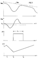
- Fig. 1 (from top to bottom) over a common time scale (time t) the rotational speed v wheel of a braked wheel including the so-called reference speed v Ref , the associated deceleration of the braked wheel (i.e. the first derivative of the one shown in the upper figure) Rotational speed over time) a wheel including a comparison value V S with respect to the deceleration, a change ⁇ V of the comparison value and the associated brake pressure p.
- the course of the wheel speed v wheel in Fig. 1 (top) shows that no axle vibrations occur.
- the wheel speed is greatly reduced due to braking, so that the deceleration a wheel at time t 1 falls below the comparison value V S and due to the reduction in brake pressure p, the wheel speed v wheel then "recovers" and the deceleration becomes an acceleration, and exceeds the comparison value V S at time t2 again. This recovery of the wheel has the result that the brake pressure p is increased again from the time t2.
- the effective threshold value is also increased, ie to the initially set comparison value V S , an additional amount .DELTA.V is added from time t.sub.2, which results in less sensitive ABS control.
- the "normal" comparison value V S is increased by an additional amount ⁇ V as shown in FIG. 1, so that the effective threshold is significantly increased for the time period T x in which the increased value ⁇ V is effective is and therefore exceeding this threshold is significantly less likely and pressure reduction at least for the time period T x is generally excluded.
- the increase in the comparison value V S by the additional amount ⁇ V to achieve an effective threshold value V S + ⁇ V is only carried out if the re-acceleration a wheel of the braked wheel takes place relatively quickly, that is to say in a relatively short period of time after the time t 1. So it is determined whether the re-acceleration of the wheel over a predetermined comparison value and whether the period between the times t1 and t2 is so short that this indicates the possibility of the presence of an axis vibration. That means that the time period from t 1 - t 2 is then approximately in the range of half an oscillation period of a resonant axis oscillation. Tolerances, ie deviations from the vehicle-specific resonant axle oscillation period, are permitted.
- the ABS control algorithm therefore assumes that there is a certain probability that the axis of the braked wheel is in an oscillation state. So that after the time t2 the axle vibration does not cause an undesirable reduction in brake pressure p (see FIG. 1, lower image), the effective threshold value is set to the amount V S + ⁇ V at time t2 and for a period of time T x ( 1), which is initially somewhat larger than a typical resonant oscillation period of the axis (cf. also FIG. 2). In the case shown in Fig.
- Fig. 2 shows an illustration in which there is an axis vibration.
- the processes up to time t z are as described above with reference to FIG. 1.
- Between the times t1 and t2 has therefore a rapid (that is to say occurring within a relatively short time interval) re-acceleration of the wheel, which was also above a relatively high extreme value, so that the effective threshold value is increased by the amount ⁇ V at time t2.
- This raising of the threshold value takes place again for the time period T x .
- the wheel deceleration a wheel falls below the comparison value V s again , which the ABS computer evaluates as a strong indicator that a Axis vibration is present.
- the time period T y is then measured in which the wheel deceleration a Rad is below the comparison value V S (cf. FIG. 2). This is the time span between the times t4 and t5.
- the ABS computer extends, after the point in time t5, the period in which the effective threshold value is increased by an additional amount ⁇ V by a further period T z , the period T z being dependent on that previously measured period of time between the times t4 and t5, ie the period of time T y .
- the set time period T z is somewhat longer than the measured time period T y .
- an axis vibration will occur as a damped vibration, as is also assumed in FIG. 2. This means that the amplitudes of the time course of the wheel deceleration a wheel decrease. Accordingly, following an initial increase in the effective threshold value by the amount ⁇ V at the time t2 each time the comparison value V S falls below at the times t4, t6 etc., the amount of the increase ⁇ V in the threshold value can be reduced, as in FIG is shown.
- the axis of the braked wheel also swings beyond the time t5 even further, but with a dampened amplitude.
- the wheel deceleration a wheel in turn falls below the comparison value V S within the time period T z , which serves as an indication to the ABS computer that the axle vibration continues.
- the time period T ' y is then measured accordingly, ie the time period between the times triosen and t7.
- the ABS computer therefore does not set the effective threshold value V S + ⁇ V to the “normal value” (ie V S ), but instead allows an increase in the effective threshold value to be effective, specifically for a period of time T ′ z , which is also set here approximately equal to half an oscillation period of a resonance oscillation of the axis. Only after the point in time t7 does the oscillating axis settle sufficiently again, so that there is no shortfall in the comparison value V S within the period T ′ z , which is why the increase in the threshold value stops at point in time t8.
- the increase ⁇ V in the threshold value is a step function in Depends on the time shown.
Abstract
Description
Die Erfindung betrifft ein Verfahren zum blockiergeschützten Bremsen der Räder eines Fahrzeuges, bei dem Bremsdruck in Abhängigkeit vom Schlupf und/oder der Drehgeschwindigkeitsänderung (positive oder negative Verzögerung) eines gebremsten Rades im Verhältnis zu zumindest einem Schwellenwert auf- oder abgebaut oder konstant gehalten wird, und bei dem während aufeinanderfolgender Regelzyklen der blockiergeschützten Bremsung die jeweiligen Wiederbeschleunigungen der gebremsten Räder gemessen werden um zur Unterdrückung insbesondere durch Schwingungen der Achse des Fahrzeuges auslösbarer unerwünschter Regelvorgänge den Schwellenwert zu variieren oder einen Abbau von Bremsdruck für eine vorgegebene Zeitspanne zu verhindern.The invention relates to a method for the anti-lock braking of the wheels of a vehicle, in which brake pressure is built up or down or kept constant as a function of the slip and / or the change in rotational speed (positive or negative deceleration) of a braked wheel in relation to at least one threshold value, and during which the respective re-accelerations of the braked wheels are measured during successive control cycles of the anti-lock braking in order to vary the threshold value to suppress undesirable control processes that can be triggered, in particular, by vibrations of the axle of the vehicle, or to prevent a reduction in brake pressure for a predetermined period of time.
Bei blockiergeschützten Fahrzeug-Bremsanlagen wird die Drehung der einzelnen Räder des Fahrzeuges ständig verfolgt und es werden insbesondere der Schlupf der gebremsten Räder sowie ihre Verzögerung ermittelt, um eine Blockierneigung des Rades festzustellen und das Blockieren zu verhindern. Sobald der Radschlupf bzw. die Verzögerung eine Blockierneigung anzeigen, was dadurch festgestellt wird, daß bestimmte, vorgegebene Schwellenwerte bezüglich Schlupf und/oder Verzögerung überschritten werden, wird ein weiterer Anstieg des Druckes in der Bremse des betroffenen Rades beendet oder der Bremsdruck abgebaut.In the case of anti-lock vehicle braking systems, the rotation of the individual wheels of the vehicle is continuously monitored, and in particular the slipping of the braked wheels and their deceleration are determined in order to determine a tendency of the wheel to lock and to prevent locking. As soon as the wheel slip or the deceleration indicate a tendency to lock, which is determined by the fact that certain predetermined threshold values with regard to slip and / or deceleration are exceeded, a further increase in the pressure in the brake of the wheel concerned is ended or the brake pressure is reduced.
Sobald das betroffene Rad aufgrund seiner Reibung mit der Fahrbahn wieder eine hinreichende Drehbeschleunigung erfahren hat, wird der Druck in der Bremse wieder erhöht, um mit dem Rad weitere Bremswirkung zu erzielen.As soon as the wheel concerned has experienced sufficient rotational acceleration due to its friction with the road, the pressure in the brake is increased again in order to achieve further braking effect with the wheel.
Bei der blockiergeschützten Regelung des Bremsdruckes geht es wesentlich darum, über alle Regelzyklen einer Bremsung die gebremsten Räder möglichst im günstigsten Bereich der bekannten Reibbeiwert/ Schlupf-Kurve laufen zu lassen.In the case of anti-lock control of the brake pressure, it is essential to let the braked wheels run as far as possible in the most favorable range of the known coefficient of friction / slip curve over all control cycles of braking.
Um eine Bremsung mit möglichst kurzem Bremsweg bei gleichzeitiger Lenkbarkeit des Fahrzeuges zu erreichen, sollte die Antiblockieranlage möglichst empfindlich und verzögerungsfrei auf Blockierneigung anzeigende Änderungen im Drehverhalten des gebremsten Rades reagieren. Hierzu wäre es erstrebenswert, die genannten Schwellenwerte möglichst empfindlich einzustellen, d.h. so, daß schon bei relativ geringen Änderungen des Rad-Drehverhaltens in Richtung auf eine Blockierneigung ein Regelzyklus mit einem Abbau des Bremsdruckes eingeleitet wird.In order to achieve braking with the shortest possible braking distance and at the same time steerability of the vehicle, the anti-lock braking system should react as sensitively and without delay to changes in the turning behavior of the braked wheel that indicate a tendency to lock. To this end, it would be desirable to set the threshold values mentioned as sensitively as possible, i.e. so that even with relatively small changes in the wheel turning behavior in the direction of a tendency to lock, a control cycle is initiated with a reduction in the brake pressure.
Einer empfindlichen Einstellung der Schwellenwerte steht aber entgegen, daß unter bestimmten, nicht unwahrscheinlichen Bedingungen gebremste Räder ein Drehverhalten zeigen können, das eine starke Drehverzögerung anzeigt, obwohl das Rad noch in einem gut bremsfähigen Zustand läuft. Diese Erscheinung ist gut bekannt und zum Beispiel in der DE-OS 33 45 729 eingehend beschrieben. Durch insbesondere Achsschwingungen können relativ große Differenzen zwischen der Fahrzeug- und der Radgeschwindigkeit auftreten, die einen instabilen Lauf des Rades vortäuschen und deshalb unerwünschte Regelvorgänge, d.h. einen unerwünschten Abbau des Bremsdruckes, auslösen können. Auch wenn das gebremste Rad in ein Schlagloch oder auf unregelmäßiger Fahrbahn fährt, kann zunächst eine ruckartige Drehbeschleunigung, gefolgt von einer starken Verzögerung, auftreten.A sensitive setting of the threshold values stands in the way of the fact that under certain, not unlikely conditions, braked wheels can show a turning behavior which indicates a strong deceleration, even though the wheel is still running in a good braking condition. This phenomenon is well known and is described in detail, for example, in DE-OS 33 45 729. Axle vibrations, in particular, can cause relatively large differences between the vehicle speed and the wheel speed, which simulate unstable running of the wheel and therefore undesirable control processes, i.e. can trigger an undesirable reduction in brake pressure. Even if the braked wheel drives into a pothole or on an irregular road, a jerky spin acceleration followed by a strong deceleration can occur.
Derartige Achsschwingungen oder dergleichen können also dazu führen, daß eng eingestellte Schwellenwerte bezüglich der Drehverzögerung des Rades überschritten werden und ein unerwünschter Regelvorgang (Druckabbau am gebremsten Rad) eingeleitet wird, obwohl das Rad nicht blockiergefährdet ist.Such axis vibrations or the like can therefore lead to narrow threshold values with respect to the Deceleration of the wheel are exceeded and an undesirable control process (pressure reduction on the braked wheel) is initiated, although the wheel is not at risk of locking.
In der gattungsbildenden DE-OS 33 45 729 wird zur Unterdrückung unerwünschter Regelvorgänge der für die Einleitung der Regelung maßgebliche Schwellenwert in Abhängigkeit von der Hochlaufbeschleunigung des geregelten Rades variiert. Hierzu wird die Hochlaufbeschleunigung des gebremsten Rades (also das Wiederanlaufen des Rades nach einer Verzögerung) ständig überwacht und dann, wenn die Hochlaufbeschleunigung einen vorgegebenen Grenzwert überschreitet, wird der für die Einleitung eines Regelvorganges, d.h. einen Druckabbau in der Bremse des Rades, maßgebliche Schwellenwert variiert. Die Variation des Schwellenwertes erfolgt in Abhängigkeit vom Maß der Hochlaufbeschleunigung. Der Schwellenwert wird also momentan auf den sich aus der Hochlaufbeschleunigung ergebenden Wert erhöht und klingt dann in einer vorgegebenen Zeitfunktion (exponentiell oder linear) auf den Grundwert wieder ab. Der Grund-Schwellenwert ist derjenige Schwellenwert, den das System normalerweise einnimmt, d.h. dann, wenn die Hochlaufbeschleunigung des Rades unter dem obengenannten Grenzwert liegt oder keine Regelung durchgeführt wird.In the generic DE-OS 33 45 729 to suppress undesired control processes, the threshold value which is decisive for initiating the control is varied as a function of the acceleration of acceleration of the controlled wheel. For this purpose, the acceleration of acceleration of the braked wheel (i.e. the restart of the wheel after a deceleration) is constantly monitored and if the acceleration of acceleration exceeds a predetermined limit value, this is used to initiate a control process, i.e. a pressure reduction in the brake of the wheel, the relevant threshold value varies. The threshold value is varied as a function of the degree of acceleration. The threshold value is therefore currently increased to the value resulting from the acceleration, and then decays to the basic value in a predetermined time function (exponential or linear). The basic threshold is the threshold that the system normally takes, i.e. then when the acceleration of acceleration of the wheel is below the above-mentioned limit value or no regulation is carried out.
Auch aus der US-PS 4 140 353 ist bereits ein Verfahren zum blockiergeschützten Bremsen bekannt, bei dem in Abhängigkeit von der Größe der Wiederbeschleunigung eines gebremsten Rades der für die Regelung maßgebliche Schwellenwert eingestellt wird.From US Pat. No. 4,140,353, a method for anti-lock braking is already known, in which the threshold value relevant for the regulation is set depending on the size of the re-acceleration of a braked wheel.
Aus der DE 38 05 270 A1 sowie der entspechenden EP 0 329 071 A2 ist bereits ein Verfahren zum Regeln des Bremsdruckes in einer blockiergeschützten Fahrzeugbremsanlage bekannt, bei dem zur Vermeidung von unerwünschten, durch Achsschwingungen, Schlaglöcher od. dergl. bedingten Regelvorgängen der Schwellenwert zu Beginn einer Druckabsenkung oder -erhöhung während eines Regelzyklus kurzzeitig um einen konstanten Betrag gegenüber einem Grund-Schwellenwert heraufgesetzt wird. Danach wird der Schwellenwert in Abhängigkeit von der Zeitspanne des Druckabbaus im vorangegangenen Regelzyklus abgesenkt.From DE 38 05 270 A1 and the corresponding EP 0 329 071 A2, a method for regulating the brake pressure in an anti-lock vehicle brake system is already known in which the threshold value at the beginning is avoided in order to avoid undesired control processes caused by axle vibrations, potholes or the like a pressure drop or increase during a control cycle is briefly raised by a constant amount compared to a basic threshold value. Then the Threshold value reduced depending on the period of pressure reduction in the previous control cycle.
Die vorliegende Erfindung beruht auf einer weitergehenden Analyse des Phänomens der Achsschwingungen und schlägt einen ABS-Regelalgorithmus vor, der eine sichere Ausschaltung von durch Achsschwingungen verursachten unerwünschten ABS-Regelungen gewährleistet.The present invention is based on a further analysis of the phenomenon of the axle vibrations and proposes an ABS control algorithm which ensures that undesired ABS controls caused by axle vibrations are reliably switched off.
Die Achsen eines Kraftfahrzeuges bilden mit allen mit ihnen elastisch oder starr verbundenen übrigen Bauteilen ein schwingungsfähiges System (Feder-Masse-System), welches bei einer Auslenkung aus der Ruhelage Schwingungen mit beträchtlichen Amplituden ausführen kann. So ist bei vielen Fahrzeugen das Federbein (z.B. vom McPherson-Typ) der Vorderachse in Längsrichtung nur über einen Stabilisator (Federstab) geführt, der in Gummilagern gehalten ist.The axles of a motor vehicle form with all other components connected to them elastically or rigidly an oscillatory system (spring-mass system) which, when deflected from the rest position, can carry out vibrations with considerable amplitudes. In many vehicles, the suspension strut (e.g. of the McPherson type) of the front axle is only guided in the longitudinal direction via a stabilizer (spring bar), which is held in rubber bearings.
Wird an einem solchen Rad nun ein Bremsmoment aufgebaut, so wird das durch die Achse und die zugehörigen Teile gebildete schwingungsfähige System entgegen der Fahrtrichtung ausgelenkt, so daß der eigentlichen Radgeschwindigkeit eine relative Achsgeschwindigkeit überlagert wird, die in diesem Fall negativ ist, d.h. es scheint so als würde das Rad abgebremst. In dieser Stellung ist das schwingungsfähige System vorgespannt und hat durch Verformung der Feder potentielle Energie aufgenommen.If a braking torque is now built up on such a wheel, the oscillatory system formed by the axle and the associated parts is deflected against the direction of travel, so that the actual wheel speed is superimposed on a relative axle speed, which in this case is negative, i.e. it seems like the wheel is being braked. In this position, the oscillatory system is pre-stressed and has absorbed potential energy by deforming the spring.
Kommt es nun in dieser Situation im Rahmen einer ABS-Regelung zu einem Abbau des Bremsdruckes und damit einer Verringerung des Bremsmomentes, so wird die Fahrzeugachse in Fahrtrichtung beschleunigt. Das vorgespannte System aus Achse und zugehörigen Teilen löst sich nun aus der beschriebenen Extremlage und schwingt über die sogenannte Null-Lage (welche dem Ruhezustand der Achse entspricht) in Fahrtrichtung nach vorne.If, in this situation, ABS braking pressure is reduced and the braking torque is reduced, the vehicle axle is accelerated in the direction of travel. The preloaded system consisting of the axle and associated parts now releases itself from the extreme position described and swings forward over the so-called zero position (which corresponds to the idle state of the axle).
Kommt es sodann im Rahmen einer ABS-Regelung wieder zu einem Aufbau des Bremsdruckes, so wird das Rad zunächst um die zusätzlich über die Null-Lage nach vorne geschwenkte Strecke verzögert, was allein schon zu einem Überschreiten des Verzögerungsschwellenwertes der ABS-Regelung führen kann. Würde die ABS-Regelung auf diese Verzögerung mit einem Druckabbausignal reagieren, käme es nicht nur zu einer uneffektiven Bremsung, sondern das System könnte sich auch wieder in Fahrtrichtung beschleunigen und es könnte die Achse sogar in einen resonanten Schwingungszustand geraten, der äußerst unerwünscht ist. Die Gefahr solcher Achsschwingungen besteht insbesondere auf Straßen mit hohen Reibbeiwerten. Der oben zitierte Stand der Technik hat erkannt, daß es in solchen Situationen zu starken Radwiederbeschleunigungen kommen kann, die dort als Anzeichen für Achsschwingungen herangezogen werden.If the brake pressure then builds up again as part of an ABS control, the wheel is first turned around additionally decelerated via the zero position, which alone can lead to the ABS control threshold being exceeded. If the ABS control responded to this delay with a pressure reduction signal, not only would the braking be ineffective, but the system could accelerate again in the direction of travel and the axis could even get into a resonant vibration state, which is extremely undesirable. Such axis vibrations are particularly dangerous on roads with high coefficients of friction. The prior art cited above has recognized that strong wheel re-accelerations can occur in such situations, which are used there as signs of axle vibrations.
Der Erfindung liegt die Aufgabe zugrunde, bei einer blockiergeschützten Fahrzeugbremsanlage das Auftreten von Achsschwingungen zuverlässig erkennbar zu machen, so daß eine Beeinträchtigung der ABS-Regelung durch Achsschwingungen vermieden werden kann.The invention has for its object to make the occurrence of axle vibrations reliably detectable in an anti-lock vehicle brake system, so that impairment of the ABS control by axle vibrations can be avoided.
Bei modernen Kraftfahrzeug-Achsen liegen die Resonanz-Schwingfrequenzen je nach Fahrzeugtyp zwischen 7 und 15 Hz. Für einen gegebenen Fahrzeugtyp kann diese Resonanzfrequenz experimentell ermittelt werden, z.B. durch Auslenkung aus der Ruhelage und Messung der Schwingungsdauer.With modern motor vehicle axles, the resonance oscillation frequencies are between 7 and 15 Hz depending on the vehicle type. For a given vehicle type, this resonance frequency can be determined experimentally, e.g. by deflection from the rest position and measurement of the period of oscillation.
Der vorliegenden Erfindung liegt die Erkenntnis zugrunde, daß eine genaue Beobachtung der Drehverzögerung eines zuvor stark wiederbeschleunigten Rades Aufschluß über mögliche Achsschwingungen liefern kann.The present invention is based on the knowledge that a precise observation of the deceleration of a previously strongly re-accelerated wheel can provide information about possible axle vibrations.
Hierzu wird erfindungsgemäß im Verlaufe einer aus mehreren Regelzyklen bestehenden ABS-Regelung für jeden Regelzyklus die Radwiederbeschleunigung beobachtet. Sobald in einem Regelzyklus eine besonders hohe Wiederbeschleunigung (eine Wiederbeschleunigung oberhalb des vorgegebenen Grenzwertes) festgestellt worden ist und überdies auch die Wiederbeschleunigung relativ rasch erfolgt ist, wird (anders als beim Stand der Technik, wo direkt aus der Wiederbeschleunigung auf eine Achsschwingung geschlossen wird) erfindungsgemäß eine weitere Messung durchgeführt und zwar bezüglich der Rad-Drehverzögerung im sich an die starke Wiederbeschleunigung unmittelbar anschließenden Regelzyklus.For this purpose, the wheel re-acceleration is observed for each control cycle in the course of an ABS control consisting of several control cycles. As soon as a particularly high re-acceleration (a re-acceleration above the predetermined limit value) has been determined in a control cycle and the re-acceleration has also taken place relatively quickly, (unlike in the prior art, where Axial vibration is deduced directly from the re-acceleration) According to the invention, a further measurement is carried out, specifically with regard to the wheel rotation deceleration in the control cycle immediately following the strong re-acceleration.
Gemäß der Erfindung wird dann
- der hochgesetzte Schwellenwert für eine vorgegebene Zeitspanne beibehalten und dann wieder auf den Grundwert abgesenkt, wenn in dieser vorgegebenen Zeitspanne keine Radverzögerung gemessen wird und auch der Schwellenwert nicht überschritten wird, wobei die vorgegebene Zeitspanne etwas länger ist als eine Achs-Schwingungsperiode einer Fahrzeugachse, wohingegen dann, wenn
- der Schwellenwert innerhalb der vorgegebenen Zeitspanne unterschritten wird, dies keinen Abbau von Bremsdruck des Rades auslöst und die Zeitspanne gemessen wird, in welcher der Schwellenwert unterschritten bleibt und dann, wenn
- diese gemessene Zeitspanne kürzer ist als eine vorgegebene Zeitspanne, ein Abbau von Bremsdruck weiter unterbunden wird für eine zusätzliche Zeitspanne, die mindestens so lang ist wie eine typische Achs-Schwingungsperiode der Fahrzeugachse.
- maintain the raised threshold value for a predetermined period of time and then reduce it back to the basic value if no wheel deceleration is measured in this predetermined period of time and the threshold value is not exceeded, the predetermined period of time being somewhat longer than an axle oscillation period of a vehicle axle, whereas then , if
- the threshold value is undershot within the predetermined period of time, this does not trigger a reduction in the brake pressure of the wheel and the period is measured in which the threshold value remains below and then when
- this measured time period is shorter than a predetermined time period, a reduction in brake pressure is further prevented for an additional time period that is at least as long as a typical axis oscillation period of the vehicle axle.
Der Erfindung liegt also die Erkenntnis zugrunde, daß für ein gegebenes Fahrzeug bei einer Achsschwingung die Verzögerung eines gebremsten Rades einen typischen schwingenden Verlauf hat, bei dem die Schwingungsperioden charakteristisch sind für die gegebene Fahrzeugachse, d.h. abhängig sind von der fahrzeugspezifischen Resonanzschwingung der Achse. Gemäß der Erfindung wird deshalb im Anschluß an eine extrem starke Wiederbeschleunigung (welche über einen vorgegebenen Vergleichswert liegt) der weitere Verlauf der Radverzögerung überwacht und dann, wenn innerhalb einer relativ kurzen vorgegebenen Zeitspanne, die z.B. etwas größer ist als die fahrzeugspezifische Resonanz-Schwingungsdauer der Achse, wieder ein schnelles Absenken der Fahrzeugverzögerung und ein anschließendes relativ schnelles Ansteigen der Fahrzeugverzögerung auftreten, auf das Vorhandensein einer Achsschwingung geschlossen und ein durch diese Achsschwingung ausgelöster unerwünschter Abbau von Bremsdruck am gebremsten Rad verhindert.The invention is therefore based on the knowledge that, for a given vehicle, the deceleration of a braked wheel with an axle vibration has a typical oscillating course, in which the oscillation periods are characteristic of the given vehicle axle, that is to say are dependent on the vehicle-specific resonance vibration of the axle. According to the invention, therefore, following an extremely strong re-acceleration (which lies above a predetermined comparison value), the further course of the wheel deceleration is monitored and then, if within a relatively short predetermined time period, which is, for example, somewhat larger than the vehicle-specific resonance oscillation period of the axle , again a rapid decrease in vehicle deceleration and a subsequent relatively rapid increase in vehicle deceleration occur to which The presence of an axle vibration is closed and an unwanted reduction in brake pressure on the braked wheel triggered by this axle vibration is prevented.
Diese Verhinderung der Auslösung unerwünschter Regelvorgänge kann z.B. dadurch erreicht werden, daß der für die Einleitung eines Druckabbaus maßgebliche Schwellenwert in Richtung auf ein unempfindlicheres Ansprechverhalten der ABS-Regelung verändert wird oder daß ganz einfach für eine vorgegebene Zeitspanne, die länger ist als eine resonante Schwingungsdauer der Achse, aber kürzer als die typische Dauer eines Regelzyklus, der Abbau von Bremsdruck ausgeschlossen wird.This prevention of triggering undesired control processes can e.g. can be achieved by changing the threshold value which is decisive for the initiation of a pressure reduction in the direction of a less sensitive response behavior of the ABS control, or by simply for a predetermined period of time which is longer than a resonant oscillation period of the axis, but shorter than the typical period a control cycle, the reduction of brake pressure is excluded.
Gemäß dieser erfindungsgemäßen Lösung wird also für das gegebene Fahrzeug ein der Resonanzschwingung der Achse zugeordneter Zeitwert ermittelt. Dieser Zeitwert entspricht einer Schwingungsperiode im Resonanzfall und läßt sich für jeden gegebenen Fahrzeugtyp experimentell ermitteln. Dieser Zeitwert wird für den gegebenen Fahrzeugtyp im Rechner der ABS-Anlage ein- und für allemal abgespeichert und steht für alle ABS-Regelungen zur Verfügung. Erfindungsgemäß wird somit im Anschluß an ein besonders hohes, über einem vorgegebenen Grenzwert liegendes Wiederbeschleunigungssignal im unmittelbar anschließenden Regelzyklus diejenige Zeitspanne gemessen, in der die Rad-Drehverzögerung unter einem vorgegebenen Grenzwert liegt, d.h. es wird diejenige Zeitspanne ermittelt, die zwischen dem Zeitpunkt liegt, in dem die Rad-Drehverzögerung den Grenzwert unterschreitet und dem Zeitpunkt, zu dem die Rad-Drehverzögerung diesen Grenzwert wieder überschreitet. Der Erfindung liegt die Erkenntnis zugrunde, daß diese Zeitspanne einen Aufschluß darüber gibt, ob sich die Fahrzeugachse in einem die ABS-Regelung erschwerenden Schwingungszustand befindet. Es wird deshalb die wie vorstehend beschrieben gemessene Zeitspanne mit dem abgespeicherten Zeitwert, welcher der halben Resonanz-Schwingungsdauer der Achse entspricht, verglichen, um bei Übereinstimmung innerhalb einer vorgegebenen Toleranz auf einen Achsschwingungszustand zu schließen. Ist ein solcher Achsschwingungszustand auf diese Weise erkannt worden, so kann er für die ABS-Regelung in vielfältiger Weise unschädlich gemacht werden, z.B. dadurch daß der Schwellenwert unempfindlicher eingestellt wird, und zwar für eine Zeitspanne, die zumindest etwas länger ist als eine Resonanz-Schwingungsdauer der Achse. Statt einer Anhebung des Schwellenwertes kann auch für eine vorgegebene Zeitspanne vorgesehen werden, daß der ABS-Rechner keine Absenkung des Bremsdruckes bewirkt, auch wenn in dieser Zeitspanne der Schwellenwert überschritten wird, was ansonsten eine Druckabsenkung zur Folge hätte.According to this solution according to the invention, a time value assigned to the resonance vibration of the axle is determined for the given vehicle. This time value corresponds to an oscillation period in the event of resonance and can be determined experimentally for any given vehicle type. This time value is saved for the given vehicle type in the computer of the ABS system and saved for all time and is available for all ABS regulations. According to the invention, following a particularly high re-acceleration signal lying above a predetermined limit value in the immediately following control cycle, the time period is measured in which the wheel rotation deceleration is below a predetermined limit value, i.e. the time period that lies between the time is determined in which the wheel rotation deceleration falls below the limit value and the time at which the wheel rotation deceleration exceeds this limit value again. The invention is based on the knowledge that this time period provides information about whether the vehicle axle is in a vibration state which complicates the ABS control. The time period measured as described above is therefore compared with the stored time value, which corresponds to half the resonance oscillation period of the axis, in order to infer an axle oscillation condition if they match within a predetermined tolerance. Is such an axis vibration condition on this Detected in this way, it can be rendered harmless for ABS control in a variety of ways, for example by making the threshold value less sensitive, for a period of time that is at least somewhat longer than a resonance oscillation period of the axis. Instead of an increase in the threshold value, it can also be provided for a predetermined period of time that the ABS computer does not bring about a reduction in the brake pressure, even if the threshold value is exceeded in this period, which would otherwise result in a pressure decrease.
Der vorstehend beschriebene ABS-Regelalgorithmus wird mit zeitgemäßer Technik dadurch realisiert, daß ein Prozessor entsprechend dem Algorithmus programmiert wird. Alle für die Realisierung der Erfindung erforderlichen Hardware-Komponenten, wie Prozessoren, Ventile, Steuermittel etc. sind in der ABS-Technik allgemein bekannt.The ABS control algorithm described above is implemented using modern technology in that a processor is programmed in accordance with the algorithm. All hardware components required for realizing the invention, such as processors, valves, control means etc., are generally known in ABS technology.
Ein für die Einleitung eines Druckabbaus maßgeblicher Schwellenwert kann etwa ein Schlupf-, Verzögerungs- oder Geschwindigkeits-Schwellenwert sein. Im folgenden wird exemplarisch ein Verzögerungsschwellenwert bei der Beschreibung eines Ausführungsbeispieles herangezogen.A threshold value that is decisive for initiating a pressure reduction can be, for example, a slip, deceleration or speed threshold value. In the following, a delay threshold value is used as an example in the description of an exemplary embodiment.
Nachfolgend wird das erfindungsgemäße blockiergeschützte Bremsverfahren anhand der Zeichung näher erläutert. Es zeigt:
- Fig. 1
- über einer gemeinsamen Zeitskala die Verläufe einer typischen Radgeschwindigkeit, Radverzögerung, Schwellwertänderung und des Zugehörigen Brensdruckes für eine blockiergeschützte Bremsung ohne Achsschwingungen und
- Fig. 2
- eine der Fig. 1 entsprechende Darstellung für eine blockiergeschützte Bremsung, bei der Achsschwingungen auftreten.
- Fig. 1
- The courses of a typical wheel speed, wheel deceleration, threshold value change and the associated braking pressure for an anti-lock braking without axle vibrations and
- Fig. 2
- a representation corresponding to FIG. 1 for an anti-lock braking, in which axle vibrations occur.
In Fig. 1 sind (von oben nach unten) über einer gemeinsamen Zeitskala (Zeit t) die Drehgeschwindigkeit vRad eines gebremsten Rades einschließlich der sogenannten Referenzgeschwindigkeit vRef, die zugehörige Verzögerung des gebremsten Rades (also die erste Ableitung der in der oberen Figur dargestellten Drehgeschwindigkeit über der Zeit) aRad einschließlich eines Vergleichswertes VS bezüglich der Verzögerung, eine Änderung ΔV des Vergleichwertes und der zugehörige Bremsdruck p aufgetragen. Der Verlauf der Radgeschwindigkeit vRad in Fig. 1 (oben) zeigt, daß keine Achsschwingungen auftreten. Die Radgeschwindigkeit wird aufgrund einer Bremsung stark abgesenkt, so daß die Verzögerung aRad zum Zeitpunkt t₁ den Vergleichswert VS unterschreitet und aufgrund des Abbaus des Bremsdruckes p sich die Radgeschwindigkeit vRad dann wieder "erholt" und auch die Verzögerung zu einer Beschleunigung wird, und den Vergleichswert VS zum Zeitpunkt t₂ wieder überschreitet. Diese Erholung des Rades hat zur Folge, daß ab dem Zeitpunkt t₂ der Bremsdruck p wieder vergrößert wird.In Fig. 1 (from top to bottom) over a common time scale (time t) the rotational speed v wheel of a braked wheel including the so-called reference speed v Ref , the associated deceleration of the braked wheel (i.e. the first derivative of the one shown in the upper figure) Rotational speed over time) a wheel including a comparison value V S with respect to the deceleration, a change ΔV of the comparison value and the associated brake pressure p. The course of the wheel speed v wheel in Fig. 1 (top) shows that no axle vibrations occur. The wheel speed is greatly reduced due to braking, so that the deceleration a wheel at time t 1 falls below the comparison value V S and due to the reduction in brake pressure p, the wheel speed v wheel then "recovers" and the deceleration becomes an acceleration, and exceeds the comparison value V S at time t₂ again. This recovery of the wheel has the result that the brake pressure p is increased again from the time t₂.
Zum Zeitpunkt t₂ wird gemäß Fig. 1 auch der effektive Schwellenwert erhöht, d.h. zum zunächst eingestellten Vergleichswert VS wird ab dem Zeitpunkt t₂ ein zusätzlicher Betrag ΔV addiert, der eine unempfindlichere ABS-Regelung zur Folge hat. Mit anderen Worten: in Abhängigkeit von der Zeit wird gemäß Fig. 1 der "normale" Vergleichswert VS um einen zusätzliche Betrag ΔV erhöht, so daß für die Zeitspanne Tx, in welcher der erhöhte Wert ΔV wirksam ist, die effektive Schwelle deutlich heraufgesetzt ist und somit ein Überschreiten dieser Schwelle deutlich unwahrscheinlicher ist und somit der Druckabbau zumindest für die Zeitspanne Tx in der Regel ausgeschlossen ist.1, the effective threshold value is also increased, ie to the initially set comparison value V S , an additional amount .DELTA.V is added from time t.sub.2, which results in less sensitive ABS control. In other words: depending on the time, the "normal" comparison value V S is increased by an additional amount ΔV as shown in FIG. 1, so that the effective threshold is significantly increased for the time period T x in which the increased value ΔV is effective is and therefore exceeding this threshold is significantly less likely and pressure reduction at least for the time period T x is generally excluded.
Die Erhöhung des Vergleichswertes VS um den zusätzlichen Betrag ΔV zur Erzielung eines effektiven Schwellenwertes VS + ΔV wird aber nur dann vorgenommen, wenn die Wiederbeschleunigung aRad des gebremsten Rades verhältnismäßig rasch, also in einer realtiv kurzen Zeitspanne nach dem Zeitpunkt t₁ erfolgt. Es wird also ermittelt, ob die Wiederbeschleunigung des Rades über einen vorgegebenen Vergleichswert liegt und ob die Zeitspanne zwischen den Zeitpunkten t₁ und t₂ so kurz ist, daß dies die Möglichkeit des Vorliegens einer Achsschwingung anzeigt. Daß heißt, die Zeitspanne von t₁ - t₂ liegt dann etwa im Bereich einer halben Schwingungsdauer einer resonanten Achsschwingung. Dabei sind Toleranzen, d.h. Abweichungen von der fahrzeugspezifischen resonanten Achs-Schwingungsdauer zugelassen.The increase in the comparison value V S by the additional amount ΔV to achieve an effective threshold value V S + ΔV is only carried out if the re-acceleration a wheel of the braked wheel takes place relatively quickly, that is to say in a relatively short period of time after the time t 1. So it is determined whether the re-acceleration of the wheel over a predetermined comparison value and whether the period between the times t₁ and t₂ is so short that this indicates the possibility of the presence of an axis vibration. That means that the time period from t 1 - t 2 is then approximately in the range of half an oscillation period of a resonant axis oscillation. Tolerances, ie deviations from the vehicle-specific resonant axle oscillation period, are permitted.
Zum Zeitpunkt t₂ geht also der erfindungsgemäße ABS-Regelalgorithmus davon aus, daß eine gewisse Wahrscheinlichkeit dafür gegeben ist, daß die Achse des gebremsten Rades sich in einem Schwingungszustand befindet. Damit im Anschluß an den Zeitpunkt t₂ die Achsschwingung keinen unerwünschten Abbau von Bremsdruck p (vgl. Fig. 1, unteres Bild) verursacht, wird zum Zeitpunkt t₂ der effektive Schwellenwert auf den Betrag VS + ΔV gesetzt und zwar für eine Zeitspanne Tx (Fig. 1), die zunächst etwas größer ist als eine typische resonante Schwingungsdauer der Achse (vgl. auch Fig. 2). Beim in Fig. 1 dargestellten Fall kommt es im Anschluß an den Zeitpunkt t₂ zu keiner Fortsetzung der Achsschwingung, d.h. die Drehgeschwindigkeit aRad des gebremsten Rades hat einen "normalen" Verlauf und nähert sich nach dem Abbau des Bremsdruckes und im Anschluß an den Zeitpunkt t₂ wieder mit zunehmendem Bremsdruck in der üblichen Weise der Referenzgeschwindigkeit vRef.At time t₂, the ABS control algorithm according to the invention therefore assumes that there is a certain probability that the axis of the braked wheel is in an oscillation state. So that after the time t₂ the axle vibration does not cause an undesirable reduction in brake pressure p (see FIG. 1, lower image), the effective threshold value is set to the amount V S + ΔV at time t₂ and for a period of time T x ( 1), which is initially somewhat larger than a typical resonant oscillation period of the axis (cf. also FIG. 2). In the case shown in Fig. 1 there is no continuation of the axis vibration at the time t₂, ie the rotational speed a wheel of the braked wheel has a "normal" course and approaches after the reduction in brake pressure and after the time t₂ again with increasing brake pressure in the usual way of the reference speed v Ref .
Dies hat zur Folge, daß in der sich an den Zeitpunkt t₂ anschließenden Zeitspanne Tx keine Absenkung der Verzögerung aRad des Rades unter den Vergleichswert VS auftritt. Der den ABS-Regelalgorithmus ausführende Computer wertet dies so, daß keine Achsschwingung auftritt, weshalb nach Ablauf der Zeitspanne Tx, also zum Zeitpunkt t₃, die Erhöhung des Schwellenwertes um den Betrag ΔV wieder rückgängig gemacht wird und der Vergleichswert VS als der "normale" Schwellenwert wirksam ist.The result of this is that in the time period T x following the time t 2 there is no reduction in the deceleration a wheel of the wheel below the comparison value V S. The computer executing the ABS control algorithm evaluates this in such a way that no axis oscillation occurs, which is why after the time period T x , ie at time t 3, the increase in the threshold value by the amount ΔV is reversed and the comparison value V S as the "normal""Threshold is effective.
Fig. 2 zeigt eine Darstellung, bei der es zu einer Achsschwingung kommt. Die Vorgänge bis zum Zeitpunkt tz sind wie vorstehend anhand von Fig. 1 beschrieben. Zwischen den Zeitpunkten t₁ und t₂ hat somit eine rasche (das heißt innerhalb eines relativ kurzen Zeitintervalls auftretende) Wiederbeschleunigung des Rades stattgefunden, die auch über einem relativ hohen Extremwert lag, so daß zum Zeitpunkt t₂ der wirksame Schwellenwert um den Betrag ΔV hochgesetzt wird. Diese Hochsetzung des Schwellenwertes erfolgt zunächst wieder für die Zeitspanne Tx. Anders als beim in Fig. 1 dargestellten Verlauf der Radgeschwindigkeit tritt aber bei Fig. 2 aufgrund einer Achsschwingung zum Zeitpunkt t₄ ein erneutes Unterschreiten der Radverzögerung aRad unter dem Vergleichswert Vs auf, was der ABS-Computer als starken Indikator dafür wertet, daß eine Achsschwingung vorliegt. Sodann wird die Zeitspanne Ty gemessen, in welcher die Radverzögerung aRad unter dem Vergleichswert VS liegt (vgl. Fig. 2). Dies ist die Zeitspanne zwischen den Zeitpunkten t₄ und t₅.Fig. 2 shows an illustration in which there is an axis vibration. The processes up to time t z are as described above with reference to FIG. 1. Between the times t₁ and t₂ has therefore a rapid (that is to say occurring within a relatively short time interval) re-acceleration of the wheel, which was also above a relatively high extreme value, so that the effective threshold value is increased by the amount ΔV at time t₂. This raising of the threshold value takes place again for the time period T x . In contrast to the course of the wheel speed shown in FIG. 1, in FIG. 2, due to an axle vibration at time t₄, the wheel deceleration a wheel falls below the comparison value V s again , which the ABS computer evaluates as a strong indicator that a Axis vibration is present. The time period T y is then measured in which the wheel deceleration a Rad is below the comparison value V S (cf. FIG. 2). This is the time span between the times t₄ and t₅.
Gemäß einer ersten Ausführungsvariante der Erfindung verlängert der ABS-Computer im Anschluß an den Zeitpunkt t₅ die Zeitspanne, in welcher der effektive Schwellenwert um einen zusätzlichen Betrag ΔV heraufgesetzt ist, um eine weitere Zeitspanne Tz, wobei die Zeitspanne Tz abhängig ist von der zuvor gemessenen Zeitspanne zwischen den Zeitpunkten t₄ und t₅, also der Zeitspanne Ty. Wie dargestellt ist, ist die gesetzte Zeitspanne Tz etwas länger als die gemessene Zeitspanne Ty.According to a first embodiment of the invention, the ABS computer extends, after the point in time t₅, the period in which the effective threshold value is increased by an additional amount ΔV by a further period T z , the period T z being dependent on that previously measured period of time between the times t₄ and t₅, ie the period of time T y . As shown, the set time period T z is somewhat longer than the measured time period T y .
Im allgemeinen wird eine Achsschwingung als gedämpfte Schwingung auftreten, wie auch in Fig. 2 angenommen ist. Dies bedeutet, daß sich die Amplituden des zeitlichen Verlaufs der Radverzögerung aRad verkleinern. Dementsprechend kann im Anschluß an ein erstmaliges Heraufsetzen des effektiven Schwellenwertes um den Betrag ΔV zum Zeitpunkt t₂ bei jedem anschließenden Unterschreiten des Vergleichswertes VS zu den Zeitpunkten t₄, t₆ etc. der Betrag der Erhöhung ΔV des Schwellenwertes herabgesetzt werden, wie in Fig. 2 ebenfalls dargestellt ist.In general, an axis vibration will occur as a damped vibration, as is also assumed in FIG. 2. This means that the amplitudes of the time course of the wheel deceleration a wheel decrease. Accordingly, following an initial increase in the effective threshold value by the amount ΔV at the time t₂ each time the comparison value V S falls below at the times t₄, t₆ etc., the amount of the increase ΔV in the threshold value can be reduced, as in FIG is shown.
Beim in Fig. 2 dargestellten Ausführungsbeispiel schwingt die Achse des gebremsten Rades auch über den Zeitpunkt t₅ hinaus noch weiter, allerdings mit gedämpfter Amplitude. Dies hat zur Folge, daß innerhalb der Zeitspanne Tz die Radverzögerung aRad wiederum den Vergleichswert VS unterschreitet, was dem ABS-Computer als Anzeichen dafür dient, daß sich die Achsschwingung fortsetzt. Dementsprechend wird dann die Zeitspanne T'y gemessen, d.h. die Zeitspanne zwischen den Zeitpunkten t₆ und t₇. Im Anschluß an den Zeitpunkt t₇ setzt deshalb der ABS-Computer den effektiven Schwellenwert VS + ΔV noch nicht auf den "Normalwert" (also VS), sondern läßt weiter eine Erhöhung des effektiven Schwellenwertes wirksam sein und zwar für eine Zeitspanne T'z, die hier ebenfalls etwa gleich einer halben Schwingungsdauer einer Resonanzschwingung der Achse gesetzt ist. Erst im Anschluß an den Zeitpunkt t₇ beruhigt sich die schwingende Achse wieder hinreichend, so daß innerhalb der Zeitspanne T'z keine Unterschreitung des Vergleichswertes VS erfolgt, weshalb zum Zeitpunkt t₈ die Erhöhung des Schwellenwertes aufhört.In the embodiment shown in Fig. 2, the axis of the braked wheel also swings beyond the time t₅ even further, but with a dampened amplitude. As a result, the wheel deceleration a wheel in turn falls below the comparison value V S within the time period T z , which serves as an indication to the ABS computer that the axle vibration continues. The time period T ' y is then measured accordingly, ie the time period between the times tpunkten and t₇. Following the time t₇, the ABS computer therefore does not set the effective threshold value V S + ΔV to the “normal value” (ie V S ), but instead allows an increase in the effective threshold value to be effective, specifically for a period of time T ′ z , which is also set here approximately equal to half an oscillation period of a resonance oscillation of the axis. Only after the point in time t₇ does the oscillating axis settle sufficiently again, so that there is no shortfall in the comparison value V S within the period T ′ z , which is why the increase in the threshold value stops at point in time t₈.
In Abwandlung des vorstehend beschriebenen Ausführungsbeispieles ist es auch möglich, die zwischen den Zeitpunkten t₄ und t₅ gemessene Zeitspanne Ty in der die Radverzögerung aRad den Vergleichswert VS unterschreitet, zu messen und mit einer zuvor für den gegebenen Fahrzeugtyp ein- und für allemal abgespeicherten Vergleichszeitspanne zu vergleichen, die typisch ist für eine Achsschwingung des gegebenen Fahrzeuges. Ergibt dieser Vergleich, daß eine hinreichende Übereinstimmung zwischen der gemessenen Zeitspanne Ty und dem Vergleichswert besteht, so schließt der ABS-Computer daraus, daß eine Achsschwingung vorliegt und bewirkt ab dem Zeitpunkt t₄, daß für eine bestimmte Zeitspanne ein Abbau des Bremsdruckes p verhindert ist. Diese bestimmte Zeitspanne wird so bemessen, daß sie hinreichend lang ist, um eine typische gedämpfte Achsschwingung voll zu erfassen, aber kürzer ist als eine typische Dauer eines Regelzyklus in einer ABS-Regelung.In a modification of the exemplary embodiment described above, it is also possible to measure the time period T y measured between the times t₄ and t₅, in which the wheel deceleration a wheel falls below the comparison value V S , and with one previously and once and for all stored for the given vehicle type To compare the comparison time period, which is typical for an axle vibration of the given vehicle. If this comparison shows that there is a sufficient correspondence between the measured time period T y and the comparison value, the ABS computer concludes that there is an axis vibration and, from time t Zeitpunkt, causes a reduction in the brake pressure p for a certain time period . This specific time period is dimensioned such that it is long enough to fully capture a typical damped axle vibration, but is shorter than a typical duration of a control cycle in an ABS control.
Im in den Fig. 1 und 2 dargestellten Ausführungsbeispiel ist die Erhöhung ΔV des Schwellenwertes als Stufenfunktion in Abhängigkeit von der Zeit dargestellt. In Abwandlung dieses Ausführungsbeispieles der Erfindung ist es auch möglich, die Erhöhung
ΔV des effektiven Schwellenwertes in Abhängigkeit vom Druck p einzustellen. Mit zunehmenden Druck wird die Erhöhung des Schwellenwertes abgesenkt, weil mit zunehmenden Druck sich auch die Radgeschwindigkeit der Fahrzeug-Referenzgeschwindigkeit vRef annähert und die ABS-Regelung wieder den typischen "Normalschwellenwert" annehmen sollte.In the exemplary embodiment shown in FIGS. 1 and 2, the increase ΔV in the threshold value is a step function in Depends on the time shown. In a modification of this embodiment of the invention, it is also possible to increase
Set ΔV of the effective threshold value as a function of pressure p. With increasing pressure, the increase in the threshold value is reduced, because with increasing pressure, the wheel speed also approaches the vehicle reference speed v Ref and the ABS control should assume the typical "normal threshold value" again.
Claims (1)
- An anti-lock braking method to retard the wheels of a vehicle, wherein(a) the dynamic wheel behavior is measured and slip as well as variations of rotational speed are determined on the basis thereof;(b) the signals thus obtained serve for a reduction of the brake pressure, for maintaining it constant, or for the renewed rise thereof when associated threshold values are exceeded;(c) the respective renewed accelerations of the wheels are measured during successive control cycles of the anti-lock protection;(d) the basic threshold value is increased at the beginning of the renewed rise of the brake pressure to prevent initiation of undesired control operations due to axle oscillations or to prohibit a reduction in brake pressure for a given period of time;(e) the raised threshold value is returned to the basic threshold value within the control cycle,characterized in that(f1) the raised threshold value (VS + ΔV) is maintained for a given period of time (Tx) and then lowered once more to its basic value (VS) if no wheel retardation (aRad) failing to reach a comparative value (VS) in respect of retardation is measured during the given period of time (Tx), the given period of time (Tx) being somewhat longer than one oscillation period of the vehicle axle,(f2)(a) in case the wheel retardation (aRad) again drops below the comparative value (VS) within the given period of time (Tx), this diminuation does not cause a reduction in brake pressure,(b) a period of time (Ty) being measured during which the deceleration of the retarded wheel (aRad) lies below the comparative value (VS), and(f3) in case this measured period of time (Ty) is shorter than a predetermined period of time (Tymax), reduction of the brake pressure continues to be precluded for an additional period of time (Ty + Tz) which is at least as long as one oscillation period of the vehicle axle.
Applications Claiming Priority (3)
| Application Number | Priority Date | Filing Date | Title |
|---|---|---|---|
| DE4028193A DE4028193C1 (en) | 1990-09-05 | 1990-09-05 | |
| PCT/EP1991/001812 WO1993005990A1 (en) | 1990-09-05 | 1991-09-23 | Process for anti-lock braking of the wheels of a vehicle |
| US08/039,439 US5342118A (en) | 1990-09-05 | 1993-04-30 | Anti-lock braking method to retard the wheels of a vehicle |
Publications (2)
| Publication Number | Publication Date |
|---|---|
| EP0559654A1 EP0559654A1 (en) | 1993-09-15 |
| EP0559654B1 true EP0559654B1 (en) | 1995-09-13 |
Family
ID=25896605
Family Applications (1)
| Application Number | Title | Priority Date | Filing Date |
|---|---|---|---|
| EP91916978A Expired - Lifetime EP0559654B1 (en) | 1990-09-05 | 1991-09-23 | Process for anti-lock braking of the wheels of a vehicle |
Country Status (6)
| Country | Link |
|---|---|
| US (1) | US5342118A (en) |
| EP (1) | EP0559654B1 (en) |
| JP (1) | JP3045768B2 (en) |
| KR (1) | KR100193391B1 (en) |
| DE (1) | DE4028193C1 (en) |
| WO (1) | WO1993005990A1 (en) |
Families Citing this family (12)
| Publication number | Priority date | Publication date | Assignee | Title |
|---|---|---|---|---|
| DE4028193C1 (en) * | 1990-09-05 | 1992-02-27 | Lucas Industries P.L.C., Birmingham, West Midlands, Gb | |
| DE4032506A1 (en) * | 1990-10-12 | 1992-04-16 | Lucas Ind Plc | METHOD FOR REGULATING THE BRAKE PRESSURE IN A BLOCK-PROTECTED VEHICLE BRAKE SYSTEM |
| US5775785A (en) * | 1994-03-25 | 1998-07-07 | Lucas Industries Plc | Anti-lock braking system having pulsed pressure re-application |
| US5615935A (en) * | 1995-09-21 | 1997-04-01 | Robert Bosch Gmbh | ABS control for a four wheel drive vehicle experiencing axle oscillations |
| DE19538545A1 (en) * | 1995-10-17 | 1997-04-24 | Teves Gmbh Alfred | Method for improving the control behavior of a brake system |
| DE19601529A1 (en) * | 1996-01-17 | 1997-07-24 | Teves Gmbh Alfred | Process for improving the control behavior of an ABS in an off-road driving situation |
| DE19705948A1 (en) * | 1997-02-17 | 1998-08-20 | Itt Mfg Enterprises Inc | Process for damping powertrain vibrations |
| US5958322A (en) | 1998-03-24 | 1999-09-28 | 3M Innovation Properties Company | Method for making dimensionally stable nonwoven fibrous webs |
| DE102008003874A1 (en) * | 2008-01-08 | 2009-07-23 | Siemens Aktiengesellschaft | Input signals providing method for regulating force induced in wheels of vehicle i.e. rail-mounted vehicle, involves determining temporal course of speed signal based on wheel speed signal to determine slip, acceleration and delay values |
| KR101417856B1 (en) * | 2010-11-16 | 2014-07-09 | 주식회사 만도 | Pressure control method of wheel using the variable threshold |
| DE102014212984A1 (en) | 2014-07-03 | 2016-01-07 | Continental Teves Ag & Co. Ohg | A method for avoiding Fehlanregelungen a slip control system of a brake system of a vehicle |
| KR102545487B1 (en) | 2018-11-15 | 2023-06-21 | 한국전력공사 | Safety device for underground structure |
Citations (1)
| Publication number | Priority date | Publication date | Assignee | Title |
|---|---|---|---|---|
| DE3345729A1 (en) * | 1983-12-17 | 1985-06-27 | Alfred Teves Gmbh, 6000 Frankfurt | METHOD AND CIRCUIT ARRANGEMENT FOR SUPPRESSING UNWANTED CONTROL PROCESSES IN SLIP-CONTROLLED BRAKE SYSTEMS |
Family Cites Families (5)
| Publication number | Priority date | Publication date | Assignee | Title |
|---|---|---|---|---|
| US4140353A (en) * | 1968-09-20 | 1979-02-20 | Kelsey-Hayes Company | Skid control system |
| DE3805270A1 (en) * | 1988-02-19 | 1989-08-31 | Lucas Ind Plc | METHOD FOR REGULATING THE BRAKE PRESSURE IN A BLOCK-PROTECTED VEHICLE BRAKE SYSTEM |
| DE3877757D1 (en) * | 1988-10-13 | 1993-03-04 | Siemens Ag | METHOD FOR DISTINATING ROTATING WHEELS OF A VEHICLE FROM DRIVELINE VIBRATIONS. |
| GB2227534B (en) * | 1988-11-17 | 1993-07-21 | Tokico Ltd | Anti-skid brake control apparatus |
| DE4028193C1 (en) * | 1990-09-05 | 1992-02-27 | Lucas Industries P.L.C., Birmingham, West Midlands, Gb |
-
1990
- 1990-09-05 DE DE4028193A patent/DE4028193C1/de not_active Expired - Lifetime
-
1991
- 1991-09-23 JP JP03515740A patent/JP3045768B2/en not_active Expired - Fee Related
- 1991-09-23 EP EP91916978A patent/EP0559654B1/en not_active Expired - Lifetime
- 1991-09-23 WO PCT/EP1991/001812 patent/WO1993005990A1/en active IP Right Grant
- 1991-09-23 KR KR1019930701528A patent/KR100193391B1/en not_active IP Right Cessation
-
1993
- 1993-04-30 US US08/039,439 patent/US5342118A/en not_active Expired - Lifetime
Patent Citations (1)
| Publication number | Priority date | Publication date | Assignee | Title |
|---|---|---|---|---|
| DE3345729A1 (en) * | 1983-12-17 | 1985-06-27 | Alfred Teves Gmbh, 6000 Frankfurt | METHOD AND CIRCUIT ARRANGEMENT FOR SUPPRESSING UNWANTED CONTROL PROCESSES IN SLIP-CONTROLLED BRAKE SYSTEMS |
Also Published As
| Publication number | Publication date |
|---|---|
| KR100193391B1 (en) | 1999-06-15 |
| JPH06502365A (en) | 1994-03-17 |
| KR930702185A (en) | 1993-09-08 |
| DE4028193C1 (en) | 1992-02-27 |
| WO1993005990A1 (en) | 1993-04-01 |
| JP3045768B2 (en) | 2000-05-29 |
| US5342118A (en) | 1994-08-30 |
| EP0559654A1 (en) | 1993-09-15 |
Similar Documents
| Publication | Publication Date | Title |
|---|---|---|
| EP0559654B1 (en) | Process for anti-lock braking of the wheels of a vehicle | |
| EP0733530B1 (en) | ABS and/or anti-slip control system for vehicle | |
| EP0329071B1 (en) | Brake pressure control method in an anti-blocking vehicle brake system | |
| DE2146825C2 (en) | Anti-lock control arrangement for pressure medium-actuated vehicle brakes | |
| EP0550849B1 (en) | Method for controlling the brake force of motorbikes | |
| EP1274596B1 (en) | Method for determining the wheel loading of a motor vehicle | |
| EP0960752A2 (en) | Method and device for determining of oscillation and moving vehicle specific quantities and use thereof | |
| EP0583252B1 (en) | Circuit arrangement for a braking system with electronic anti-lock regulation | |
| DE4032506C2 (en) | ||
| DE2726738C2 (en) | Circuit arrangement for regulating the brake pressure in anti-lock vehicle brake systems | |
| DE3836680A1 (en) | CIRCUIT ARRANGEMENT FOR A VEHICLE WITH DRIVE-SLIP CONTROL | |
| DE3806213C2 (en) | ||
| EP0451240B1 (en) | Process for controlling the braking pressure in a vehicle braking system with antilock braking system | |
| WO1990006869A1 (en) | Antilock brake adjusting system | |
| EP0960042B1 (en) | Method for recognizing and damping wheel and drive train vibrations | |
| DE4430462A1 (en) | Procedure for quickly recognizing an emergency wheel | |
| DE102004053695B4 (en) | Method for damping the body and chassis or wheel vibrations of a motor vehicle | |
| DE4320904C2 (en) | Anti-lock control system | |
| DE19705948A1 (en) | Process for damping powertrain vibrations | |
| EP0913306A2 (en) | Procedure to correct a vehicle reference speed | |
| EP0340634B1 (en) | Brake pressure control procedure in an antilock-vehicle-brake arrangement | |
| DE10216877B4 (en) | Method and device for improved balancing of pressure sensors | |
| DE19746573B4 (en) | experienced and device for braking pressure influencing | |
| DE102021131065A1 (en) | Active chassis control for a motor vehicle | |
| DE10200950A1 (en) | Method and device for detecting dangerous driving maneuvers |
Legal Events
| Date | Code | Title | Description |
|---|---|---|---|
| PUAI | Public reference made under article 153(3) epc to a published international application that has entered the european phase |
Free format text: ORIGINAL CODE: 0009012 |
|
| 17P | Request for examination filed |
Effective date: 19930428 |
|
| AK | Designated contracting states |
Kind code of ref document: A1 Designated state(s): FR GB IT |
|
| 17Q | First examination report despatched |
Effective date: 19941202 |
|
| GRAA | (expected) grant |
Free format text: ORIGINAL CODE: 0009210 |
|
| AK | Designated contracting states |
Kind code of ref document: B1 Designated state(s): FR GB IT |
|
| GBT | Gb: translation of ep patent filed (gb section 77(6)(a)/1977) |
Effective date: 19951017 |
|
| ITF | It: translation for a ep patent filed |
Owner name: MODIANO & ASSOCIATI S.R.L. |
|
| ET | Fr: translation filed | ||
| PLBE | No opposition filed within time limit |
Free format text: ORIGINAL CODE: 0009261 |
|
| STAA | Information on the status of an ep patent application or granted ep patent |
Free format text: STATUS: NO OPPOSITION FILED WITHIN TIME LIMIT |
|
| 26N | No opposition filed | ||
| REG | Reference to a national code |
Ref country code: GB Ref legal event code: IF02 |
|
| REG | Reference to a national code |
Ref country code: GB Ref legal event code: 732E |
|
| PGFP | Annual fee paid to national office [announced via postgrant information from national office to epo] |
Ref country code: GB Payment date: 20060804 Year of fee payment: 16 |
|
| PGFP | Annual fee paid to national office [announced via postgrant information from national office to epo] |
Ref country code: FR Payment date: 20060906 Year of fee payment: 16 |
|
| REG | Reference to a national code |
Ref country code: GB Ref legal event code: 732E |
|
| GBPC | Gb: european patent ceased through non-payment of renewal fee |
Effective date: 20070923 |
|
| REG | Reference to a national code |
Ref country code: FR Ref legal event code: ST Effective date: 20080531 |
|
| PG25 | Lapsed in a contracting state [announced via postgrant information from national office to epo] |
Ref country code: FR Free format text: LAPSE BECAUSE OF NON-PAYMENT OF DUE FEES Effective date: 20071001 |
|
| PG25 | Lapsed in a contracting state [announced via postgrant information from national office to epo] |
Ref country code: GB Free format text: LAPSE BECAUSE OF NON-PAYMENT OF DUE FEES Effective date: 20070923 |
|
| PGFP | Annual fee paid to national office [announced via postgrant information from national office to epo] |
Ref country code: IT Payment date: 20080912 Year of fee payment: 18 |
|
| PG25 | Lapsed in a contracting state [announced via postgrant information from national office to epo] |
Ref country code: IT Free format text: LAPSE BECAUSE OF NON-PAYMENT OF DUE FEES Effective date: 20090923 |